California Code of Regulations
Title 24, Part 2, Volume 2.5
California Building
Standards Commission
Based on the 2009 International Residential Code®
California Code of Regulations
Title 24, Part 2, Volume 2.5
California Building
Standards Commission
Based on the 2009 International Residential Code®

EFFECTIVE DATE: January 1, 2011
(For Errata and supplements, See History Note Appendix)
Public Domain: U.S. Court of Appeals, Fifth Circuit, 99-40632
2010 California Residential Code
California Code of Regulations, Title 24, Part 2.5
First Printing: June 2010
ISBN 978-1 -58001-975-0
Copyright © 2010
Held by
California Building Standards Commission
2525 Natomas Park Drive, Suite 130
Sacramento, CA 95833-2936
ALL RIGHTS RESERVED. This 2010 California Residential Code contains substantial copyrighted material from the 2009 International Residential Code, which is a copyrighted work owned by the International Code Council, Inc. Without advance written permission from the copyright owner, no part of this book may be reproduced, distributed or transmitted in any form or by any means, including, without limitation, electronic, optical or mechanical means (by way of example and not limitation, photocopying, or recording by or in an information storage retrieval system). For information on permission to copy material exceeding fair use, please contact: Publications, 4051 West Flossmoor Road, Country Club Hills, IL 60478. Phone 1-888-ICC-SAFE (422-7233).
Trademarks: “International Code Council,” the “International Code Council” logo and the “International Residential Code” and trademarks of the International Code Council, Inc.
PRINTED IN THE U.S.A.
This document is Part 2.5 of 12 parts of the official triennial compilation and publication of the adoptions, amendments and repeal of administrative regulations to California Code of Regulations, Title 24, also referred to as the California Building Standards Code. This part is known as the California Residential Code.
The California Building Standards Code is published in its entirety every three years by order of the California legislature, with supplements published in intervening years. The California legislature delegated authority to various State agencies, boards, commissions and departments to create building regulations to implement the State’s statutes. These building regulations or standards, have the same force of law, and take effect 180 days after their publication unless otherwise stipulated. The California Building Standards Code applies to occupancies in the State of California as annotated.
A city, county, or city and county may establish more restrictive building standards reasonably necessary because of local climatic, geological or topographical conditions. Findings of the local condition(s) and the adopted local building standard(s) must be filed with the California Building Standards Commission to become effective and may not be effective sooner than the effective date of this edition of the California Building Standards Code. Local building standards that were adopted and applicable to previous editions of the California Building Standards Code do not apply to this edition without appropriate adoption and the required filing.
Should you find publication (e.g., typographical) errors or inconsistencies in this code or wish to offer comments toward improving its format, please address your comments to:
California Building Standards Commission
2525 Natomas Park Drive, Suite 130
Sacramento, CA 95833–2936
Phone: (916) 263-0916
FAX: (916) 263-0959
Web Page: www.bsc.ca.gov
The 2010 California Building Standards Code (Code) was developed through the outstanding collaborative efforts of the Department of Housing and Community Development, the Division of State Architect, the Office of the State Fire Marshal, the Office of Statewide Health Planning and Development, the California Energy Commission, and the Building Standards Commission (Commission).
This collaborative effort included the assistance of the Commission’s Code Advisory Committees and many other volunteers that worked tirelessly to assist the Commission in the production of this Code.
Governor Arnold Schwarzenegger
Members of the Building Standards Commission
Acting Secretary Tom Sheehy – Chair
Isam Hasenin – Vice-Chair
James Barthman
Craig Daley
Susan Dowty
Tony Hoffman
Christina Jamison
Stephen Jensen
Michael Paravagna
Richard Sawhill
Steven Winkel
David Walls – Executive Director
Thomas Morrison – Deputy Executive Director
For questions on California state agency amendments; please refer to the contact list on the following page.
California Agency Information Contact List
| California Energy Commission | |
| Energy Hotline | (800) 772-3300 or (916) 654-5106 |
| Building Efficiency Standards | |
| Appliance Efficiency Standards | |
| Compliance Manual/Forms | |
| California State Lands Commission | |
| Marine Oil Terminals | (562) 499-6317 |
| California State Library | |
| Resources and Information | (916) 654-0261 |
| Government Publication Section | (916) 654-0069 |
| Corrections Standards Authority | |
| Local Adult Jail Standards | (916) 324-1914 |
| Local Juvenile Facility Standards | (916) 324-1914 |
| Department of Consumer Affairs—Acupuncture Board | |
| Office Standards | (916) 445-3021 |
| Department of Consumer Affairs—Board of Pharmacy | |
| Pharmacy Standards | (916) 574-7900 |
| Department of Consumer Affairs—Bureau of Barbering and Cosmetology | |
| Barber and Beauty Shop and | (916) 574-7570 |
| College Standards | (800) 952-5210 |
| Department of Consumer Affairs—Bureau of Home Furnishings and Thermal Insulation | |
| Insulation Testing Standards | (916) 574-2041 |
| Department of Consumer Affairs—Structural Pest Control Board | |
| Structural Standards | (800) 737-8188 (916) 561-8708 |
| Department of Consumer Affairs—Veterinary Medical Board | |
| Veterinary Hospital Standards | (916) 263-2610 |
| Department of Food and Agriculture | |
| Meat & Poultry Packing Plant Standards | (916) 654-1447 |
| Dairy Standards | (916) 654-1447 |
| Department of Public Health | |
| Organized Camps Standards | (916) 449-5661 |
| Public Swimming Pools Standards | (916) 449-5693 |
| Asbestos Standards | (510) 620-2874 |
| Department of Housing and Community Development | |
| Residential—Hotels, Motels, Apartments Single-Family Dwellings | (916) 445-9471 |
| Permanent Structures in Mobilehome and Special Occupancy Parks | (916) 445-9471 |
| Factory-Built Housing, Manufactured Housing and Commercial Modular | (916) 445-3338 |
| Mobilehomes—Permits & Inspections | |
| Northern Region | (916) 255-2501 |
| Southern Region | (951) 782-4420 |
| Employee Housing Standards | (916) 445-9471 |
| Department of Water Resources | |
| Gray Water Installations Standards | (916) 651-9667 |
| Division of the State Architect—Access Compliance | |
| Access Compliance Standards | (916) 445-8100 |
| Division of the State Architect—Structural Safety | |
| Public Schools Standards | (916) 445-8100 |
| Essential Services Building Standards | (916) 445-8100 |
| Community College Standards | (916) 445-8100 |
| Division of the State Architect—State Historical Building Safety Board | |
| Alternative Building Standards | (916) 445-8100 |
| Office of Statewide Health Planning and Development | |
| Hospital Standards | (916) 440-8409 |
| Skilled Nursing Facility Standards | (916) 440-8409 |
| Clinic Standards | (916) 440-8409 |
| Permits | (916) 440-8409 |
| Office of the State Fire Marshal | |
| Code Development and Analysis | (916) 445-8200 |
| Fire Safety Standards | (916) 445-8200 |
| Fireplace Standards | (916) 445-8200 |
| Day-Care Centers Standards | (916) 445-8200 |
| Exit Standards | (916) 445-8200 |
To distinguish between model code language and the incorporated California amendments, including exclusive California standards, California amendments will appear in italics.
[BSC] This symbol within a section identifies which State agency(s), by its “acronym,” has amended a section of the model code.
| Legend of Acronyms of Adopting State Agencies | |
|---|---|
| BSC | California Building Standards Commission |
| SFM | Office of the State Fire Marshal |
| HCD | Department of Housing and Community Development |
| DSA-AC | Division of the State Architect-Access Compliance |
| DSA-SS | Division of the State Architect-Structural Safety |
| DSA-SS/CC | Division of the State Architect-Structural Safety/Community Colleges |
| OSHPD | Office of Statewide Health Planning and Development |
| CSA | Corrections Standards Authority |
| DPH | Department of Public Health |
| AGR | Department of Food and Agriculture |
| CEC | California Energy Commission |
| CA | Department of Consumer Affairs: |
| Board of Barbering and Cosmetology | |
| Board of Examiners in Veterinary Medicine | |
| Board of Pharmacy | |
| Acupuncture Board | |
| Bureau of Home Furnishings | |
| Structural Pest Control Board | |
| SL | State Librarian |
| SLC | State Lands Commission |
| DWR | Department of Water Resources |
Symbols in the margins indicate the status of code changes as follows:
This symbol indicates that a change has been made to a California amendment.
This symbol indicates California deletion of California language.
v viFormat of the California Matrix Adoption Tables
The matrix adoption tables, which follow, show the user which state agencies have adopted and/or amended given sections of the model code. The building application determines which state agency’s adoptions apply. See Section’s 102 through 114 for building applications and enforcement responsibilities.
Agencies are grouped together, based on either local or state enforcement responsibilities. For example, regulations from SFM are enforced both at the state and local levels; therefore, SFM is listed twice in each adoption table indicating state enforcement responsibilities and local enforcement responsibilities.
The side headings identify the scope of state agencies’ adoption as follows:
Adopt the entire IRC chapter without state amendments.
If there is an “X” under a particular state agency’s acronym on this row; this means that particular state agency has adopted the entire model code chapter without any state amendments.
Example:
| Adopting agency | BSC | SFM | HCD | DSA | OSHPD | CSA | DPH | AGR | DWR | CA | SL | SLC | |||||||
|---|---|---|---|---|---|---|---|---|---|---|---|---|---|---|---|---|---|---|---|
| 1 | 2 | 1-AC | AC | SS | SS/CC | 1 | 2 | 3 | 4 | ||||||||||
| Adopt entire chapter | X | ||||||||||||||||||
| Adopt entire chapter as amended (amended sections listed below) | S | A | M | P | L | E | |||||||||||||
| Adopt only those sections that are listed below | |||||||||||||||||||
| Chapter/Section | |||||||||||||||||||
Adopt the entire IRC chapter as amended, state-amended sections are listed below:
If there is an “X” under a particular state agency’s acronym on this row, it means that particular state agency has adopted the entire model code chapter; with state amendments.
Each state-amended section that the agency has added to that particular chapter is listed. There will be an “X” by that particular section, under the agency’s acronym, as well as an “X” by each section that the agency has adopted.
Example:
| Adopting agency | BSC | SFM | HCD | DSA | OSHPD | CSA | DPH | AGR | DWR | CA | SL | SLC | |||||||
|---|---|---|---|---|---|---|---|---|---|---|---|---|---|---|---|---|---|---|---|
| 1 | 2 | 1-AC | AC | SS | SS/CC | 1 | 2 | 3 | 4 | ||||||||||
| Adopt entire chapter | |||||||||||||||||||
| Adopt entire chapter as amended (amended sections listed below) | X | ||||||||||||||||||
| Adopt only those sections that are listed below | S | A | M | P | L | E | |||||||||||||
| Chapter/Section | |||||||||||||||||||
| 202 | X | ||||||||||||||||||
Adopts only those sections that are listed below:
If there is an “X” under a particular state agency’s acronym on this row, it means that particular state agency is adopting only specific model code or state-amended sections within this chapter. There will be an “X” in the column under the agency’s acronym, as well as an “X” by each section that the agency has adopted.
Example:
| Adopting agency | BSC | SFM | HCD | DSA | OSHPD | CSA | DPH | AGR | DWR | CA | SL | SLC | |||||||
|---|---|---|---|---|---|---|---|---|---|---|---|---|---|---|---|---|---|---|---|
| 1 | 2 | 1-AC | AC | SS | SS/CC | 1 | 2 | 3 | 4 | ||||||||||
| Adopt entire chapter | |||||||||||||||||||
| Adopt entire chapter as amended (amended sections listed below) | |||||||||||||||||||
| Adopt only those sections that are listed below | X | X | S | A | M | P | L | E | |||||||||||
| Chapter 1 | |||||||||||||||||||
| 202 | X | X | S | A | M | P | L | E | |||||||||||
| 202 | X | X | C | O | N | T. | |||||||||||||
| 203 | X | X | |||||||||||||||||
| 203 | X | X | |||||||||||||||||
[BSC] This symbol within a section identifies which State agency(s), by its “acronym”, has amended a section of the model code.
viii| Part I—Administrative | 3 | |
| CHAPTER 1 SCOPE AND APPLICATION | 3 | |
| DIVISION I—CALIFORNIA ADMINISTRATION | 3 | |
| Section | ||
| 1.1 | General | 3 |
| 1.2 | Reserved | 6 |
| 1.3 | Reserved | 6 |
| 1.4 | Reserved | 6 |
| 1.5 | Reserved | 6 |
| 1.6 | Reserved | 6 |
| 1.7 | Reserved | 6 |
| 1.8 | Department of Housing and Community Development (HCD) | 6 |
| 1.8.1 | Authority and Abbreviations | 6 |
| 1.8.2 | Local Enforcing Agency | 7 |
| 1.8.3 | Permits, Fees, Applications and Inspections | 8 |
| 1.8.4 | Right of Entry for Enforcement | 8 |
| 1.8.5 | Local Modification by Ordinance or Regulation | 9 |
| 1.8.6 | Alternate Materials, Designs, Tests and Methods of Construction | 9 |
| 1.8.7 | Appeals Board | 10 |
| 1.8.8 | Unsafe Buildings or Structures | 10 |
| 1.8.9 | Other Building Regulations | 11 |
| 1.9 | Reserved | 11 |
| 1.10 | Reserved | 11 |
| 1.11 | Office of the State Fire Marshal | 11 |
| 1.12 | Reserved | 15 |
| 1.13 | Reserved | 15 |
| 1.14 | Reserved | 15 |
| DIVISION II ADMINISTRATION | 16 | |
| Section | ||
| R101 | General | 16 |
| R102 | Applicability | 16 |
| R103 | Department of Building Safety | 16 |
| R104 | Duties and Powers of the Building Official | 17 |
| R105 | Permits | 18 |
| R106 | Construction Documents | 19 |
| R107 | Temporary Structures and Uses | 20 |
| R108 | Fees | 21 |
| R109 | Inspection | 21 |
| R110 | Certificate of Occupancy | 22 |
| R111 | Service Utilities | 22 |
| R112 | Board of Appeals | 23 |
| R113 | Violations | 23 |
| R114 | Stop Work Order | 24 |
| Part II—Definitions | 29 | |
| CHAPTER 2 DEFINITIONS | 29 | |
| Section | ||
| R201 | General | 29 |
| R202 | Definitions | 29 |
| Part III— Building Planning and Construction | 41 | |
| CHAPTER 3 BUILDING PLANNING | 41 | |
| Section | ||
| R301 | Design Criteria | 41 |
| R302 | Fire-Resistant Construction | 68 |
| R303 | Light, Ventilation and Heating | 73 |
| R304 | Minimum Room Areas | 74 |
| R305 | Ceiling Height | 75 |
| R306 | Sanitation | 75 |
| R307 | Toilet, Bath and Shower Spaces | 75 |
| R308 | Glazing | 75 |
| R309 | Garages and Carports | 78 |
| R310 | Emergency Escape and Rescue Openings | 78 |
| R311 | Means of Egress | 79 |
| R312 | Guards | 82 |
| R313 | Automatic Fire Sprinkler Systems | 82 |
| R314 | Smoke Alarms | 94 |
| R315 | Carbon Monoxide Alarms | 96 |
| R316 | Foam Plastic | 97 |
| R317 | Protection of Wood and Wood Based Products Against Decay | 99 |
| R318 | Protection Against Subterranean Termites | 100 |
| R319 | Site Address | 101 |
| R320 | Accessibility | 101 |
| R321 | Elevators and Platform Lifts | 101 |
| R322 | Flood-Resistant Construction | 101 |
| R323 | Storm Shelters | 104 |
| R324 | Reserved | 104 |
| R325 | Special Provisions for Licensed 24-Hour Care Facilities in Group R-3.1 | 104 |
| R326 | Large Family Day-Care Homes | 107 |
| R327 | Materials and Construction Methods for Exterior Wildfire Exposure | 108 |
| R327.1 | Scope, Purpose and Application | 108 |
| R327.2 | Definitions | 110 |
| R327.3 | Standards of Quality | 110 |
| R327.4 | Ignition Resistant Construction | 111 |
| R327.5 | Roofing | 112 |
| R327.6 | Vents | 112 |
| R327.7 | Exterior Covering | 112 |
| R327.8 | Exterior Windows and Doors | 114 |
| R327.9 | Decking | 115 |
| R327.10 | Accessory Structures | 115 |
| R328 | Electric Vehicle | 115 |
| CHAPTER 4 FOUNDATIONS | 119 | |
| Section | ||
| R401 | General | 119 |
| R402 | Materials | 120 |
| R403 | Footings | 121 |
| R404 | Foundation and Retaining Walls | 127 |
| R405 | Foundation Drainage | 156 |
| R406 | Foundation Waterproofing and Dampproofing | 157 |
| R407 | Columns | 158 |
| R408 | Under-Floor Space | 158 |
| CHAPTER 5 FLOORS | 163 | |
| Section | ||
| R501 | General | 163 |
| R502 | Wood Floor Framing | 163 |
| R503 | Floor Sheathing | 174 |
| R504 | Pressure Preservatively Treated-Wood Floors (On Ground) | 176 |
| R505 | Steel Floor Framing | 176 |
| R506 | Concrete Floors (On Ground) | 196 |
| CHAPTER 6 WALL CONSTRUCTION | 199 | |
| Section | ||
| R601 | General | 199 |
| R602 | Wood Wall Framing | 199 |
| R603 | Steel Wall Framing | 241 |
| R604 | Wood Structural Panels | 315 |
| R605 | Particleboard | 315 |
| R606 | General Masonry Construction | 315 |
| R607 | Unit Masonry | 323 |
| R608 | Multiple Wythe Masonry | 324 |
| R609 | Grouted Masonry | 325 |
| R610 | Glass Unit Masonry | 327 |
| R611 | Exterior Concrete Wall Construction | 328 |
| R612 | Exterior Windows and Doors | 399 |
| R613 | Structural Insulated Panel Wall Construction | 402 |
| CHAPTER 7 WALL COVERING | 413 | |
| Section | ||
| R701 | General | 413 |
| R702 | Interior Covering | 413 |
| R703 | Exterior Covering | 416 |
| CHAPTER 8 ROOF-CEILING CONSTRUCTION | 431 | |
| Section | ||
| R801 | General | 431 |
| R802 | Wood Roof Framing | 431 |
| R803 | Roof Sheathing | 457 |
| R804 | Steel Roof Framing | 457 |
| R805 | Ceiling Finishes | 479 |
| R806 | Roof Ventilation | 479 |
| R807 | Attic Access | 489 |
| CHAPTER 9 ROOF ASSEMBLIES | 493 | |
| Section | ||
| R901 | General | 493 |
| R902 | Roof Classification | 493 |
| R903 | Weather Protection | 493 |
| R904 | Materials | 495 |
| R905 | Requirements for Roof Coverings | 495 |
| R906 | Roof Insulation | 503 |
| R907 | Reroofing | 504 |
| CHAPTER 10 CHIMNEYS AND FIREPLACES | 507 | |
| Section | ||
| R1001 | Masonry Fireplaces | 507 |
| R1002 | Masonry Heaters | 511 |
| R1003 | Masonry Chimneys | 511 |
| R1004 | Factory-Built Fireplaces | 516 |
| R1005 | Factory-Built Chimneys | 516 |
| R1006 | Exterior Air Supply | 516 |
| Part IV—Energy Conservation | 517 | |
| Part V—Mechanical | 519 | |
| Part VI—Fuel Gas | 521 | |
| Part VII—Plumbing | 523 | |
| Part VIII—Electrical | 525 | |
| Part IX—Referenced Standards | 529 | |
| CHAPTER 44 REFERENCED STANDARDS | 529 | |
| APPENDIX A SIZING AND CAPACITIES OF GAS PIPING | 555 | |
| APPENDIX B SIZING OF VENTING SYSTEMS SERVING APPLIANCES EQUIPPED WITH DRAFT HOODS, CATECORY I APPLIANCES, AND APPLIANCES LISTED FOR USE WITH TYPE B VENTS | 569 | |
| APPENDIX C EXIT TERMINALS OF MECHANICAL DRAFT AND DIRECT-VENT VENTING SYSTEMS | 581 | |
| APPENDIX D RECOMMENDED PROCEDURE FOR SAFETY INSPECTION OF AN EXISTING APPLIANCE INSTALLATION | 585 | |
| APPENDIX E MANUFACTURED HOUSING USED AS DWELLINGS | 589 | |
| Section | ||
| AE101 | Scope | 589 |
| AE102 | Application to Existing Manufactured Homes and Building Service Equipment | 589 |
| AE201 | Definitions | 590 |
| AE301 | Permits | 590 |
| AE302 | Application for Permit | 590 |
| AE303 | Permits Issuance. | 591 |
| AE304 | Fees | 591 |
| AE305 | Inspections | 592 |
| AE306 | Special Inspections | 593 |
| AE307 | Utility Service | 593 |
| AE401 | Occupancy Classification | 593 |
| AE402 | Location on Property | 596 |
| AE501 | Design | 593 |
| AE502 | Foundation Systems | 594 |
| AE503 | Skirting and Perimeter Enclosures | 594 |
| AE504 | Structural Additions | 594 |
| AE505 | Building Service Equipment | 594 |
| AE506 | Exits | 595 |
| AE507 | Occupancy, Fire Safety and Energy Conservation Standards | 595 |
| AE600 | Special Requirements for Foundation Systems | 595 |
| AE601 | Footings and Foundations | 595 |
| AE602 | Pier Construction | 595 |
| AE603 | Height of Piers | 595 |
| AE604 | Anchorage Installations | 595 |
| AE605 | Ties, Materials and Installation | 596 |
| AE606 | Referenced Standards | 596 |
| APPENDIX F RADON CONTROL METHODS | 599 | |
| Section | ||
| AF101 | Scope | 599 |
| AF102 | Definitions | 599 |
| AF103 | Requirements | 599 |
| APPENDIX G SWIMMING POOLS, SPAS AND HOT TUBS | 609 | |
| Section | ||
| AG101 | General | 609 |
| AG102 | Definitions | 609 |
| AG103 | Swimming Pools | 609 |
| AG104 | Spas and Hot Tubs | 609 |
| AG105 | Barrier Requirements | 609 |
| AG106 | Entrapment Protection for Swimming Pool and Spa Suction Outlets | 611 |
| AG107 | Abbreviations | 611 |
| AG108 | Standards | 611 |
| APPENDIX H PATIO COVERS | 615 | |
| Section | ||
| AH101 | General | 615 |
| AH102 | Definition | 615 |
| AH103 | Permitted Uses | 615 |
| AH104 | Design Loads | 615 |
| AH105 | Light and Ventilation/Emergency Egress | 615 |
| AH106 | Footings | 615 |
| AH107 | Special Provisions for Aluminum Screen Enclosures in Hurricane-Prone Regions | 615 |
| APPENDIX I PRIVATE SEWAGE DISPOSAL | 619 | |
| Section | ||
| A1101 | General | 619 |
| APPENDIX J EXISTING BUILDINGS AND STRUCTURES | 623 | |
| Section | ||
| AJ101 | Purpose and Intent | 623 |
| AJ102 | Compliance | 623 |
| AJ103 | Preliminary Meeting | 623 |
| AJ104 | Evaluation of an Existing Building | 623 |
| AJ105 | Permit | 624 |
| AJ201 | Definitions | 624 |
| AJ301 | Repairs | 624 |
| AJ401 | Renovations | 625 |
| AJ501 | Alterations | 625 |
| AJ601 | Reconstruction | 626 |
| APPENDIX K SOUND TRANSMISSION | 629 | |
| Section | ||
| AK101 | General | 629 |
| AK102 | Air-Borne Sound | 629 |
| AK103 | Structural-Borne Sound | 629 |
| AK104 | Referenced Standards | 629 |
| APPENDIX L PERMIT FEES | 633 | |
| APPENDIX M HOME DAY CARE—R-3 OCCUPANCY | 637 | |
| APPENDIX N VENTING METHODS | 641 | |
| APPENDIX O GRAY WATER RECYCLING SYSTEMS | 651 | |
| AO101 | General | 651 |
| AO102 | Systems for Flushing Water Closets and Urinals | 651 |
| AO103 | Subsurface Landscape Irrigation Systems | 653 |
| APPENDIX P SIZING OF WATER PIPING SYSTEM | 659 | |
| AP101 | General | 659 |
| AP102 | Information Required | 659 |
| AP103 | Selection of Pipe Size | 659 |
| AP201 | Selection of Pipe Size | 676 |
| APPENDIX Q ICC INTERNATIONAL RESIDENTIAL CODE ELECTRICAL PROVISIONS/NATIONAL ELECTRICAL CODE CROSS-REFERENCE | 681 | |
| APPENDIX R AREAS PROTECTED BY THE FACILITIES OF THE CENTRAL VALLEY FLOOD PROTECTION PLAN | 697 | |
| HISTORY NOTE | 703 | |
| INDEX | 705 | |
| Adopting agency | BSC | SFM | HCD | DSA | OSHPD | CSA | DPH | AGR | DWR | CEC | CA | SL | SLC | ||||||
|---|---|---|---|---|---|---|---|---|---|---|---|---|---|---|---|---|---|---|---|
| 1 | 2 | 1–AC | AC | SS | 1 | 2 | 3 | 4 | |||||||||||
| The state agency does not adopt sections identified with the following symbol: † | |||||||||||||||||||
| Adopt entire chapter | |||||||||||||||||||
| Adopt entire chapter as amended (amended sections listed below) | |||||||||||||||||||
| Adopt only those sections that are listed below | X | X | X | ||||||||||||||||
| Chapter/Section | |||||||||||||||||||
| Division 1 | |||||||||||||||||||
| 1.1 through 1.1.12 | X | X | X | ||||||||||||||||
| 1.8 though 1.8.9.2 | X | X | |||||||||||||||||
| 1.11 though 1.11.10 | X | ||||||||||||||||||
| Division II | |||||||||||||||||||
| R104.2–R104.4 | X | ||||||||||||||||||
| R104.9–R109.1 | X | ||||||||||||||||||
| R105.1 | X | ||||||||||||||||||
| R105.2 Building: Items 1–10 | X | X | |||||||||||||||||
| Electrical: | † | † | |||||||||||||||||
| Gas: | † | † | |||||||||||||||||
| Mechanical: | † | † | |||||||||||||||||
| R105.2.1–R105.2.2 | X | ||||||||||||||||||
| R105.3–R105.3.1 | X | ||||||||||||||||||
| R105.4 | X | ||||||||||||||||||
| R105.6 | X | ||||||||||||||||||
| R105.7 | X | ||||||||||||||||||
| R106–R106.5 | X | ||||||||||||||||||
| R107–R107.4 | X | ||||||||||||||||||
| R109.1 | X | X | X | ||||||||||||||||
| R109.1.1 | X | X | |||||||||||||||||
| R109.1.1.1 | X | X | |||||||||||||||||
| R109.1.2 | † | † | |||||||||||||||||
| R109.1.3 | X | X | |||||||||||||||||
| R109.1.4 | X | X | X | ||||||||||||||||
| R109.1.4.1 | X | X | |||||||||||||||||
| R109.1.5 | X | X | X | ||||||||||||||||
| R109.1.5.1 | X | X | X | ||||||||||||||||
| R109.1.5.2 | X | X | |||||||||||||||||
| R109.1.6 | X | X | X | ||||||||||||||||
| R109.2–R109.4 | X | ||||||||||||||||||
| R110.1–R110.5 | X | ||||||||||||||||||
| R111.1–R111.3 | X | ||||||||||||||||||
| R113.1–R113.2 | X | ||||||||||||||||||
| R114.1–R114.2 | X | ||||||||||||||||||
1.1.1 Title. These regulations shall be known as the California Residential Code, may be cited as such and will be referred to herein as “this code.” The California Residential Code is Part 2.5 of twelve parts of the official compilation and publication of the adoption, amendment and repeal of building regulations to the California Code of Regulations, Title 24, also referred to as the California Building Standards Code. This part incorporates by adoption the 2009 International Residential Code of the International Code Council with necessary California amendments.
1.1.2 Purpose. The purpose of this code is to establish the minimum requirements to safeguard the public health, safety and general welfare through structural strength, means of egress facilities, stability, access to persons with disabilities, sanitation, adequate lighting and ventilation, and energy conservation; safety to life and property from fire and other hazards attributed to the built environment; and to provide safety to fire fighters and emergency responders during emergency operations.
1.1.3 Scope. The provisions of this code shall apply to the construction, alteration, movement, enlargement, replacement, repair, equipment, use and occupancy, location, maintenance, removal and demolition of every detached one-and two-family dwelling, townhouse not more than three stories above grade plane in height with a separate means of egress and structures accessory thereto throughout the State of California.
Exception: Live/work units complying with the requirements of Section 419 of the California Building Code shall be permitted to be built as one- and two-family dwellings or townhouses. Fire suppression required by Section 419.5 of the California Building Code when constructed under the California Residential Code for one- and two-family dwellings shall conform to Section 903.3.1.3 of the California Building Code.
1.1.3.1 Classification. Structures or portions of structures shall be classified with respect to occupancy in one or more of the groups listed below. A room or space that is intended to be occupied at different times for different purposes shall comply with all of the requirements that are applicable to each of the purposes for which the room or space will be occupied. Structures with multiple occupancies or uses shall comply with Section 508 of the California Building Code. Where a structure is proposed for a purpose that is not specifically provided for in this code, such structure shall be classified in the group that the occupancy most nearly resembles, according to the fire safety and relative hazard involved in accordance with this code or the California Building Code.
1.1.3.1.1 Residential Group R. Residential Group R includes, among others, the use of a building or structure, or a portion thereof, for sleeping purposes when not classified as an Institutional Group I. Residential occupancies shall include the following:
R-3 Residential occupancies where the occupants are primarily permanent in nature and not classified as Group R-1, R-2, R-2.1, R-3.1, R-4 or I, including:
Buildings that do not contain more than two dwelling units.
Townhouses not more than three stories above grade in height with a separate means of egress.
Adult facilities that provide accommodations for six or fewer persons of any age for less than 24-hours. Licensing categories that may use this classification include, but are not limited to: Adult Day Programs.
Child care facilities that provide accommodations for six or fewer persons of any age for less than 24-hours. Licensing categories that may use this classification include, but are not limited to: Day-care Center for Mildly III Children, Infant Care Center and School Age Child Day-care Center.
Family Day-care Homes that provide accommodations for 14 or fewer children, in the provider's own home for less than 24-hours.
Congregate living facilities or congregate residences with 16 or fewer persons.
R-3.1 This occupancy group may include facilities licensed by a governmental agency for a residentially based 24-hour care facility providing accommodations for six or fewer clients of any age. Clients may be classified as ambulatory, nonambulatory or bedridden. A Group R-3.1 occupancy shall meet the requirements for construction as defined for Group R-3, except as otherwise provided for in Section R325 Special Provisions For Licensed 24-Hour Care Facilities in a Group R-3.1 Occupancy. This group may include:
Adult Residential Facilities
Congregate Living Health Facilities
Foster Family Homes
Group Homes
Intermediate Care Facilities for the developmentally disabled habilitative
3Intermediate Care Facilities for the Developmentally disabled nursing
Nurseries for the full-time care of children under the age of six, but not including “infants” as defined in Section 202
Residential Care Facilities for the Elderly Small Family Homes and Residential Care Facilities for the chronically ill
Exception: Foster Family Homes or Group Homes licensed by the Department of Social Services which provide nonmedical board, room and care for six or fewer ambulatory children or children two years of age or younger, and which do not have any nonambulatory clients shall not be subject to regulations found in Section R325.
Pursuant to Health and Safety Code Section 13143 with respect to these exempted facilities, no city, county or public district shall adopt or enforce any requirement for the prevention of fire or for the protection of life and property against fire and panic unless the requirement would be applicable to a structure regardless of the special occupancy. Nothing shall restrict the application of state or local housing standards to such facilities if the standards are applicable to residential occupancies and are not based on the use of the structure as a facility for ambulatory children. For the purpose of this exception, ambulatory children does not include relatives of the licensee or the licensee's spouse.
Large Family Day-Care Homes. See Section R326.
1.1.3.1.2 Utility and Miscellaneous Group U. Buildings and structures of an accessory character and miscellaneous structures not classified in any specific occupancy shall be constructed, equipped and maintained to conform to the requirements of this code commensurate with the fire and life hazard incidental to their occupancy. Group U shall include, but not be limited to, the following:
Agricultural buildings
Aircraft hangars, accessory to a one- or two-family residence (See Section 412.5 of the California Building Code)
Barns
Carports
Fences more than 6 feet (1829 mm) high
Grain silos, accessory to a residential occupancy
Greenhouses
Livestock shelters
Private garages
Retaining walls
Sheds
Stables
Tanks
Towers
1.1.3.2 Regulated buildings, structures and applications. The model code, state amendments to the model code, and/or state amendments where there are no relevant model code provisions shall apply to detached one- and two-family dwellings, townhouses and structures accessory thereto. State agencies with regulatory authority are referenced in the Matrix Adoption Table and as specified in Sections 1.2 through 1.14, except where modified by local ordinance pursuant to Section 1.1.8. When adopted by a state agency, the provisions of this code shall be enforced by the appropriate enforcing agency, but only to the extent of authority granted to such agency by the state legislature.
Note: See Preface to distinguish the model code provisions from the California provisions.
1.1.4 Appendices. Provisions contained in the appendices of this code shall not apply unless specifically adopted by a state agency or adopted by a local enforcing agency in compliance with Health and Safety Code Section 18901 et seq. for Building Standards Law, Health and Safety Code Section 17950 for State Housing Law and Health and Safety Code Section 13869.7 for Fire Protection Districts. See Section 1.1.8 of this code.
1.1.5 Referenced codes. The codes, standards and publications adopted and set forth in this code, including other codes, standards and publications referred to therein are, by title and date of publication, hereby adopted as standard reference documents of this code. When this code does not specifically cover any subject related to building design and construction, recognized
4architectural or engineering practices shall be employed. The National Fire Codes, standards and the Fire Protection Handbook of the National Fire Protection Association are permitted to be used as authoritative guides in determining recognized fire prevention engineering practices.
1.1.6 Nonbuilding standards, orders and regulations. Requirements contained in the International Residential Code, or in any other referenced standard, code or document, which are not building standards as defined in Health and Safety Code Section 18909, shall not be constructed as part of the provisions of this code. For nonbuilding standards, orders and regulations, see other titles of the California Code of Regulations.
1.1.7 Order of precedence and use.
1.1.7.1 Differences. In the event of any differences between these building standards and the standard reference documents, the text of these building standards shall govern.
1.1.7.2 Specific provisions. Where a specific provision varies from a general provision, the specific provision shall apply.
1.1.7.3 Conflicts. When the requirements of this code conflict with the requirements of any other part of the California Building Standards Code, Title 24, the most restrictive requirements shall prevail.
1.1.7.3.1 Detached one- and two-family dwellings.Detached one–and two-family dwellings and townhouses not more than three stories above grade plane with a separate means of egress and their accessory structures shall not be required to comply with the more restrictive requirements contained in Title 24, Part 2, the California Building Code, unless the proposed structure(s) exceed the design limitations established in the California Residential Code user is specifically directed to use the California Building Code.
1.1.8 City, county, or city and county amendments, additions or deletions. The provisions of this code do not limit the authority of city, county, or city and country governments to establish more restrictive and reasonably necessary differences to the provisions contained in this code pursuant to complying with Section 1.1.8.1. The effective date of amendments, additions or deletions to this code by city, county, or city and county filed pursuant to Section 1.1.8.1 shall be the date filed. However, in no case shall the amendments, additions or deletions to this code be effective any sooner than the effective date of this code.
Local modifications shall comply with Health and Safety Code Section 18941.5 for Building Standards Law, Health and Safety Code Section 17958 for State Housing Law or Health and Safety Code Section 13869.7 for Fire Protection Districts.
1.1.8.1 Findings and filings.
Exception: Hazardous building ordinances and programs mitigating unreinforced masonry buildings.
1.1.9 Effective date of this code. Only those standards approved by the California Building Standards Commission that are effective at the time an application for building permit is submitted shall apply to the plans and specifications for, and to the construction performed under, that permit. For the effective dates of the provisions contained in this code, see the History Note page of this code.
1.1.10 Availability of codes. At least one complete copy each of Titles 8, 19, 20, 24 and 25 with all revisions shall be maintained in the office of the building official responsible for the administration and enforcement of this code. Each state department concerned and each city, county, or city and county shall have an up-to-date copy of the code available for public inspection. See Health and Safety Code Section 18942(d) (1) and (2).
1.1.11 Format. This part fundamentally adopts the International Residential Code by reference on a chapter-by-chapter basis. Such adoption is reflected in the Matrix Adoption Table of each chapter of this part. When the Matrix Adoption Table makes no reference to a specific chapter of the International Residential Code, such chapter of the International Residential Code is not adopted as a portion of this code.
1.1.12 Validity. If any chapter, section, subsection, sentence, clause or phrase of this code is for any reason held to be unconstitutional, contrary to statute, exceeding the authority of the state as stipulated by statutes or otherwise inoperative, such decision shall not affect the validity of the remaining portion of this code.
5SECTION 1.2
Reserved
SECTION 1.3
Reserved
SECTION 1.4
Reserved
SECTION 1.5
Reserved
SECTION 1.6
Reserved
SECTION 1.7
Reserved
1.8.1.1 General. The Department of Housing and Community Development is authorized by law to promulgate and adopt building standards and regulations for several types of building applications. These applications are grouped and identified by abbreviation in the Matrix Adoption Table to show which model code sections and amendments are applicable to each application. The applications under the authority of the Department of Housing and Community Development are listed in Sections 1.8.1.1.1 through 1.8.1.1.3.
1.8.1.1.1 Housing construction. Application –Hotels, motels, lodging houses, apartment houses, dwellings, dormitories, condominiums, shelters for homeless persons, congregate residences, employee housing, factory-built housing and other types of dwellings containing sleeping accommodations with or without common toilet or cooking facilities including accessory buildings, facilities and uses thereto. Sections of this code which pertain to applications listed in this section are identified in the Matrix Adoption Table using the abbreviation "HCD 1."
Enforcing agency—Local building department or the Department of Housing and Community Development.
Authority cited—Health and Safety Code Sections 17040, 17050, 17920.9, 17921, 17921.3, 17921.6, 17921.10, 17922, 17922.6, 17922.12, 17927, 17928, 17959.6, 18300, 18552, 18554, 18620, 18630, 18640, 18670, 18690, 18691, 18865, 18871.3, 18871.4, 18873, 18873.1, 18873.2, 18873.3, 18873.4, 18873.5, 18938.3, 18944.11 and 19990; and Government Code Section 12955.1.
Reference—Health and Safety Code Sections 17000 through 17062.5, 17910 through 17995.5, 18200 through 18700, 18860 through 18874, 19960 through 19997; and Government Code Sections 12955.1 and 12955.1.1.
1.8.1.1.2 Housing accessibility. Application–Covered multifamily dwellings as defined in Chapter 11A of the California Building Code (CBC) including, but not limited to, lodging houses, dormitories, timeshares, condominiums, shelters for homeless persons, congregate residences, apartment houses, dwellings, employee housing, factory-built housing and other types of dwellings containing sleeping accommodations with or without common toilet or cooking facilities.
Disabled access regulations promulgated under HCD authority are located in Chapter 11A of the California Building Code (CBC) and are identified in the Matrix Adoption Table by the abbreviation “HCD 1-AC.”Application of such provisions shall be in conjunction with other requirements of the Building Standards Code and apply only to newly constructed “Covered multifamily dwellings” as defined in CBC Chapter 11A.“HCD 1-AC ”applications include, but are not limited to, the following:
"HCD 1-AC" building standards generally do not apply to public use areas or public accommodations such as hotels and motels or public housing. Public use areas, public accommodations, public housing and housing which is publicly funded as defined in the CBC are subject to the Division of the State Architect (DSA-AC) and are referenced in CBC Section 1.9.1.
Enforcing agency—Local building department or the Department of Housing and Community Development.
Authority cited—Health and Safety Code Sections 17040, 17050, 17920.9, 17921, 17921.3, 17921.6, 17921.10, 17922, 17922.6, 17922.12, 17927, 17928,
617959.6, 18300, 18552, 18554, 18620, 18630, 18640, 18670, 18690, 18691, 18865, 18871.3, 18871.4, 18873, 18873.1, 18873.2, 18873.3, 18873.4, 18873.5, 18938.3, 18944.11 and 19990; and Government Code Section 12955.1.
Reference—Health and Safety Code Sections 17000 through 17062.5, 17910 through 17995.5, 18200 through 18700, 18860 through 18874, 19960 through 19997; and Government Code Sections 12955.1 and 12955.1.1.
1.8.1.1.3 Permanent buildings in mobilehome parks and special occupancy parks. Application–Permanent buildings, and permanent accessory buildings or structures, constructed within mobilehome parks and special occupancy parks that are under the control and ownership of the park operator. Sections of this code which pertain to applications listed in this section are identified in the Matrix Adoption Table using the abbreviation “HCD 2.”
Enforcing agency—Local building department or other local agency responsible for the enforcement of Health and Safety Code, Division 13, Part 2.1, commencing with Section 18200 for mobilehome parks and Health and Safety Code, Division 13, Part 2.3, commencing with Section 18860 for special occupancy parks; or the Department of Housing and Community Development.
Authority cited—Health and Safety Code Sections 17040, 17050, 17920.9, 17921, 17921.3, 17921.6, 17921.10, 17922, 17922.6, 17922.12, 17927, 17928, 17959.6, 18300, 18552, 18554, 18620, 18630, 18640, 18670, 18690, 18691, 18865, 18871.3, 18871.4, 18873, 18873.1, 18873.2, 18873.3, 18873.4, 18873.5, 18938.3, 18944.11 and 19990; and Government Code Section 12955.1.
Reference—Health and Safety Code Sections 17000 through 17062.5, 17910 through 17995.5, 18200 through 18700, 18860 through 18874, 19960 through 19997; and Government Code Sections 12955.1 and 12955.1.1.
1.8.2.1 Duties and powers. The building department of every city, county, or city and county shall enforce all the provisions of law, this code, and the other rules and regulations promulgated by the Department of Housing and Community Development pertaining to the installation, erection, construction, reconstruction, movement, enlargement, conversion, alteration, repair, removal, demolition or arrangement of apartment houses, hotels, motels, lodging houses and dwellings, including accessory buildings, facilities and uses thereto.
The provisions regulating the erection and construction of dwellings and appurtenant structures shall not apply to existing structures as to which construction is commenced or approved prior to the effective date of these regulations. Requirements relating to use, maintenance and occupancy shall apply to all dwellings and appurtenant structures approved for construction or constructed before or after the effective date of this code.
For additional information regarding the use and occupancy of existing buildings and appurtenant structures, see California Code of Regulations, Title 25, Division 1, Chapter 1, Subchapter 1, commencing with Article 1, Section 1.
1.8.2.2 Laws, rules and regulations. Other than the building standards contained in this code, and notwithstanding other provisions of law, the statutory authority and location of the laws, rules and regulations to be enforced by local enforcing agencies are listed by statute in Sections 1.8.2.2.1 through 1.8.2.2.5 below:
1.8.2.2.1 State Housing Law. Refer to the State Housing Law, California Health and Safety Code, Division 13, Part 1.5, commencing with Section 17910 and California Code of Regulations, Title 25, Division 1, Chapter 1, Subchapter 1, commencing with Section 1, for the erection, construction, reconstruction, movement, enlargement, conversion, alteration, repair, removal, demolition or arrangement of apartment houses, hotels, motels, lodging houses and dwellings, including accessory buildings, facilities and uses thereto.
1.8.2.2.2 Mobilehome Parks Act. Refer to the Mobilehome Parks Act, California Health and Safety Code, Division 13, Part 2.1, commencing with Section 18200 and California Code of Regulations, Title 25, Division 1, Chapter 2, commencing with Section 1000 for mobilehome park administrative and enforcement authority, permits, plans, fees, violations, inspections and penalties both within and outside mobilehome parks.
Exception: Mobilehome parks where the Department of Housing and Community Development is the enforcing agency.
1.8.2.2.3 Special Occupancy Parks Act. Refer to the Special Occupancy Parks Act, California Health and Safety Code, Division 13, Part 2.3, commencing with Section 18860 and California Code of Regulations, Title 25, Division 1, Chapter 2.2, commencing with Section 2000 for special occupancy park administrative and enforcement authority, permits, fees, violations, inspections and penalties both within and outside of special occupancy parks.
Exception: Special occupancy parks where the Department of Housing and Community Development is the enforcing agency.
1.8.2.2.4 Employee Housing Act. Refer to the Employee Housing Act, California Health and Safety Code, Division 13, Part 1, commencing with Section 17000 and California Code of Regulations, Title 25, Division 1, Chapter 1, Subchapter 3, commencing with Section 600 for employee housing administrative and enforcement authority, permits, fees, violations, inspections and penalties.
1.8.2.2.5 Factory-Built Housing Law. Refer to the Factory-Built Housing Law, California Health and Safety
7Code, Division 13, Part 6, commencing with Section 19960 and California Code of Regulations, Title 25, Division 1, Chapter 3, Subchapter 1, commencing with Section 3000 for factory-built housing administrative and enforcement authority, permits, fees, violations, inspections and penalties.
1.8.3.1 Permits. A written construction permit shall be obtained from the enforcing agency prior to the erection, construction, reconstruction, installation, moving or alteration of any building or structure.
Exceptions:
- Work exempt from permits as specified in Chapter 1, Administration, Division II, Section R105.2.
- Changes, alterations or repairs of a minor nature not affecting structural features, egress, sanitation, safety or accessibility as determined by the enforcing agency.
Exemptions from permit requirements shall not be deemed to grant authorization for any work to be done in any manner in violation of other provisions of law or this code.
1.8.3.2 Fees. Subject to other provisions of law, the governing body of any city, county, or city and county may prescribe fees to defray the cost of enforcement of rules and regulations promulgated by the Department of Housing and Community Development. The amount of the fees shall not exceed the amount reasonably necessary to administer or process permits, certificates, forms or other documents, or to defray the costs of enforcement. For additional information, see State Housing Law, Health and Safety Code, Division 13, Part 1.5, Section 17951 and California Code of Regulations, Title 25, Division 1, Chapter 1, Subchapter 1, Article 3, commencing with Section 6.
1.8.3.3 Plan review and time limitations. Subject to other provisions of law, provisions related to plan checking, prohibition of excessive delays and contracting with or employment of private parties to perform plan checking are set forth in State Housing Law, Health and Safety Code Section 17960.1, and for employee housing, in Health and Safety Code Section 17021.
1.8.3.3.1 Retention of plans. The building department of every city, county, or city and county shall maintain an official copy, microfilm, electronic or other type of photographic copy of the plans of every building, during the life of the building, for which the department issued a building permit.
Exceptions:
- Single or multiple dwellings not more than two stories and basement in height.
- Garages and other structures appurtenant to buildings listed in Exception 1.
- Farm or ranch buildings appurtenant to buildings listed in Exception 1.
- Any one-story building where the span between bearing walls does not exceed 25 feet (7620 mm), except a steel frame or concrete building.
All plans for common interest developments as defined in Section 1351 of the California Civil Code shall be retained. For additional information regarding plan retention and reproduction of plans by an enforcing agency, see Health and Safety Code Sections 19850 through 19852.
1.8.3.4 Inspections. Construction or work for which a permit is required shall be subject to inspection by the building official, and such construction or work shall remain accessible and exposed for inspection purposes until approved. Approval as a result of an inspection shall not be construed to be an approval of a violation of the provisions of this code or other regulations of the Department of Housing and Community Development. Required inspections are listed in the Matrix Adoption Table and in Chapter 1, Administration, Division II. See Section R109.1.
1.8.4.1 General. Subject to other provisions of law, officers and agents of the enforcing agency may enter and inspect public and private properties to secure compliance with the rules and regulations promulgated by the Department of Housing and Community Development. For limitations and additional information regarding enforcement, see the following:
1.8.5.1 General. Subject to other provisions of law, a city, county, or city and county may make changes to the provisions adopted by the Department of Housing and Community Development. If any city, county, or city and county does not amend, add or repeal by local ordinances or regulations the provisions published in this code or other regulations promulgated by the Department of Housing and Community Development, those provisions shall be applicable and shall become effective 180 days after publication by the California Building Standards Commission. Amendments, additions and deletions to this code adopted by a city, county, or city and county pursuant to California Health and Safety Code Sections 17958.5, 17958.7 and 18941.5, together with all applicable portions of this code, shall also become effective 180 days after publication of the California Building Standards Code by the California Building Standards Commission.
1.8.5.2 Findings, filings and rejections of local modifications. Prior to making any modifications or establishing more restrictive building standards, the governing body shall make express findings and filings, as required by California Health and Safety Code Section 17958.7, showing that such modifications are reasonably necessary due to local climatic, geological or topographical conditions. No modification shall become effective or operative unless the following requirements are met:
Nothing in this section shall limit the authority of fire protection districts pursuant to California Health and Safety Code Section 13869.7(a).
1.8.6.1 General. The provisions of this code as adopted by the Department of Housing and Community Development are not intended to prevent the use of any alternate material, appliance, installation, device, arrangement, design or method of construction not specifically prescribed by this code. Consideration and approval of alternates shall comply with Section 1.8.6.2 for local building departments and Section 1.8.6.3 for the Department of Housing and Community Development.
1.8.6.2 Local building departments. The building department of any city, county, or city and county may approve alternates for use in the erection, construction, reconstruction, movement, enlargement, conversion, alteration, repair, removal, demolition or arrangement of an apartment house, hotel, motel, lodging house, dwelling or an accessory structure, except for the following:
1.8.6.2.1 Approval of alternates. The consideration and approval of alternates by a local building department shall comply with the following procedures and limitations:
For additional information regarding approval of alternates by a building department pursuant to the State Housing Law, see California Health and Safety Code Section 17951(e) and California Code of Regulations, Title 25, Division 1, Chapter 1, Subchapter 1.
1.8.6.3 Department of Housing and Community Development. The Department of Housing and Community Development may approve alternates for use in the erection, construction, reconstruction, movement, enlargement, conversion, alteration, repair, removal or demolition of an
9apartment house, hotel, motel, lodging house, dwelling or an accessory thereto. The consideration and approval of alternates shall comply with the following:
1.8.7.1 General. Every city, county, or city and county shall establish a local appeals board and a housing appeals board. The local appeals board and housing appeals board shall each be comprised of at least five voting members that shall serve at the pleasure of the city, county, or city and county. Appointees shall not be employees of the jurisdiction and shall be qualified and specifically knowledgeable in the California Building Standards Codes and applicable local ordinances.
1.8.7.2 Definitions. The following terms shall for the purposes of this section have the meaning shown.
HOUSING APPEALS BOARD.The board or agency of a city, county, or city and county which is authorized by the governing body of the city, county, or city and county to hear appeals regarding the requirements of the city, county or city and county relating to the use, maintenance and change of occupancy of buildings and structures, including requirements governing alteration, additions, repair, demolition and moving. In any area in which there is no such board or agency, “Housing Appeals Board” means the local appeals board having jurisdiction over the area.
LOCAL APPEALS BOARD. The board or agency of a city, county, or city and county which is authorized by the governing body of the city, county, or city and county to hear appeals regarding the building requirements of the city, county, or city and county. In any area in which there is no such board or agency, “ Local Appeals Board” means the governing body of the city, county, or city and county having jurisdiction over the area.
1.8.7.3 Appeals. Except as otherwise provided in law, any person, firm or corporation adversely affected by a decision, order or determination by a city, county, or city and county relating to the application of building standards published in the California Building Standards Code, or any other applicable rule or regulation adopted by the Department of Housing and Community Development, or any lawfully enacted ordinance by a city, county, or city and county, may appeal the issue for resolution to the local appeals board or housing appeals board as appropriate.
The local appeals board shall hear appeals relating to new building construction, and the housing appeals board shall hear appeals relating to existing buildings.
1.8.8.1 Authority to enforce. Subject to other provisions of law, the administration, enforcement, actions, proceedings, abatement, violations and penalties for unsafe buildings and structures are contained in the following statutes and regulations:
1.8.8.2 Actions and proceedings. Subject to other provisions of law, punishments, penalties and fines for violations of building standards are contained in the following statutes and regulations:
1.8.9.1 Existing structures. Subject to the requirements of California Health and Safety Code Sections 17912, 17920.3, 17922, 17922.3, 17958.8 and 17958.9, provisions relating to existing structures (additions, alterations and repairs) shall only apply as identified in the California Building Code Chapter 34 Matrix Adoption Table under the authority of the Department of Housing and Community Development as listed in Sections 1.8.1.1.1 through 1.8.1.1.3 of this code.
1.8.9.2 Moved structures. Subject to the requirements of California Health and Safety Code Sections 17922.3 and 17958.9, provisions relating to a moved residential structure are located in CBC Chapter 34 and shall only apply as identified in the CBC Chapter 34 Matrix Adoption Table under the authority of the Department of Housing and Community Development as listed in Sections 1.8.1.1.1 through 1.8.1.1.3 of this code.
SECTION 1.9
Reserved
SECTION 1.9
Reserved
1.11.1 SFM—Office of the State Fire Marshal. Specific scope of application of the agency responsible for enforcement, the enforcement agency and the specific authority to adopt and enforce such provisions of this code, unless otherwise stated.
Application:
Institutional, educational or any similar occupancy. Any building or structure used or intended for use as an asylum, jail, mental hospital, hospital, sanitarium, home for the aged, children’s nursery, children’s home, school or any similar occupancy of any capacity.
Authority cited—Health and Safety Code Section 13143.
Reference—Health and Safety Code Section 13143.
Assembly or similar place of assemblage. Any theater, dancehall, skating rink, auditorium, assembly hall, meeting hall, nightclub, fair building or similar place of assemblage where 50 or more persons may gather together in a building, room or structure for the purpose of amusement, entertainment, instruction, deliberation, worship, drinking or dining, awaiting transportation, or education.
Authority cited—Health and Safety Code Section 13143.
Reference—Health and Safety Code Section 13143.
Small family day-care homes.
Authority cited—Health and Safety Code Sections 1597.45, 1597.54, 13143 and 17921.
Reference—Health and Safety Code Section 13143.
Large family day-care homes.
Authority cited—Health and Safety Code Sections 1597.45, 1597.54, 13143 and 17921.
Reference—Health and Safety Code Section 13143.
Residential facilities and residential facilities for the elderly.
Authority cited—Health and Safety Code Section 13133.
Reference—Health and Safety Code Section 13143.
Any state institution or other state-owned or state-occupied building.
Authority cited—Health and Safety Code Section 13108.
Reference—Health and Safety Code Section 13143.
High-rise structures.
Authority cited—Health and Safety Code Section 13211.
Reference—Health and Safety Code Section 13143.
Motion picture production studios.
Authority cited—Health and Safety Code Section 13143.1.
Reference—Health and Safety Code Section 13143.
Organized camps.
Authority cited—Health and Safety Code Section 18897.3.
Reference—Health and Safety Code Section 13143.
Residential. All hotels, motels, lodging houses, apartment houses and dwellings, including congregate residences and buildings and structures accessory thereto. Multiple-story structures existing on January 1, 1975, let for human habitation, including and limited to, hotels, motels and apartment houses, less than 75 feet (22 860
11mm) above the lowest floor level having building access, wherein rooms used for sleeping are let above the ground floor.
Authority cited—Health and Safety Code Sections 13143.2 and 17921.
Reference—Health and Safety Code Section 13143.
Residential care facilities. Certified family care homes, out-of-home placement facilities, halfway houses, drug and/or alcohol rehabilitation facilities and any building or structure used or intended for use as a home or institution for the housing of any person of any age when such person is referred to or placed within such home or institution for protective social care and supervision services by any governmental agency.
Authority cited—Health and Safety Code Section 13143.6.
Reference—Health and Safety Code Section 13143.
Tents, awnings or other fabric enclosures used in connection with any occupancy.
Authority cited—Health and Safety Code Section 13116.
Reference—Health and Safety Code Section 13143.
Fire alarm devices, equipment and systems in connection with any occupancy.
Authority cited—Health and Safety Code Section 13114.
Reference—Health and Safety Code Section 13143.
Hazardous materials.
Authority cited—Health and Safety Code Section 13143.9
Reference—Health and Safety Code Section 13143.
Flammable and combustible liquids.
Authority cited—Health and Safety Code Section 13143.6.
Reference—Health and Safety Code Section 13143.
Public school automatic fire detection, alarm and sprinkler systems.
Authority cited—Health and Safety Code Section 13143 and California Education Code Article 7.5, Sections 17074.50, 17074.52 and 17074.54.
Reference— Government Code Section 11152.5, Health and Safety Code Section 13143 and California Education Code Chapter 12.5, Leroy F. Greene School Facilities Act of 1998, Article 1.
Wildland-Urban interface fire area.
Authority cited—Health and Safety Code Sections 13143, 13108.5(a) and 18949.2(b) and (c) and Government Code Section 51189.
Reference—Health and Safety Code Sections 13143, Government Code Sections 51176, 51177, 51178 and 51179 and Public Resources Code Sections 4201 through 4204.
1.11.2 Duties and powers of the enforcing agency.
1.11.2.1 Enforcement.
1.11.2.1.1 The responsibility for enforcement of building standards adopted by the State Fire Marshal and published in the California Building Standards Code relating to fire and panic safety and other regulations of the State Fire Marshal shall except as provided in Section 1.11.2.1.2 be as follows:
1.11.2.1.2 Pursuant to Health and Safety Code Section 13108, and except as otherwise provided in this section, building standards adopted by the State Fire Marshal published in the California Building Standards Code relating to fire and panic safety shall be enforced by the State Fire Marshal in all state-owned buildings, state-occupied buildings and state institutions throughout the state. Upon the written request of the chief fire official of any city, county, or fire protection district, the State Fire Marshal may authorize such chief fire official
12and his or her authorized representatives, in their geographical area of responsibility, to make fire prevention inspections of state-owned or state-occupied buildings, other than state institutions, for the purpose of enforcing the regulations relating to fire and panic safety adopted by the State Fire Marshal pursuant to this section and building standards relating to fire and panic safety published in the California Building Standards Code. Authorization from the State Fire Marshal shall be limited to those fire departments or fire districts which maintain a fire prevention bureau staffed by paid personnel.
Pursuant to Health and Safety Code Section 13108, any requirement or order made by any chief fire official who is authorized by the State Fire Marshal to make fire prevention inspections of state-owned or state-occupied buildings, other than state institutions, may be appealed to the State Fire Marshal. The State Fire Marshal shall, upon receiving an appeal and subject to the provisions of Chapter 5 (commencing with Section 18945) of Part 2.5 of Division 13 of the Health and Safety Code, determine if the requirement or order made is reasonably consistent with the fire and panic safety regulations adopted by the State Fire Marshal and building standards relating to fire and panic safety published in the California Building Code.
Any person may request a code interpretation from the State Fire Marshal relative to the intent of any regulation or provision adopted by the State Fire Marshal. When the request relates to a specific project, occupancy or building, the State Fire Marshal shall review the issue with the appropriate local enforcing agency prior to rendering such code interpretation.
1.11.2.1.3 Pursuant to Health and Safety Code Section 13112, any person who violates any order, rule or regulation of the State Fire Marshal is guilty of a misdemeanor punishable by a fine of not less than $100.00 or more than $500.00, or by imprisonment for not less than six months, or by both. A person is guilty of a separate offense each day during which he or she commits, continues or permits a violation of any provision of, or any order, rule or regulation of, the State Fire Marshal as contained in this code.
Any inspection authority who, in the exercise of his or her authority as a deputy State Fire Marshal, causes any legal complaints to be filed or any arrest to be made shall notify the State Fire Marshal immediately following such action.
1.11.2.2 Right of entry. The fire chief of any city, county or fire protection district, or such person’s authorized representative, may enter any state institution or any other state-owned or state-occupied building for the purpose of preparing a fire suppression preplanning program or for the purpose of investigating any fire in a state-occupied building.
The State Fire Marshal, his or her deputies or salaried assistants, the chief of any city or county fire department or fire protection district and his or her authorized representatives may enter any building or premises not used for dwelling purposes at any reasonable hour for the purpose of enforcing this chapter. The owner, lessee, manager or operator of any such building or premises shall permit the State Fire Marshal, his or her deputies or salaried assistants and the chief of any city or county fire department or fire protection district and his or her authorized representatives to enter and inspect them at the time and for the purpose stated in this section.
1.11.2.3 More restrictive fire and panic safety building standards.
1.11.2.3.1 Any fire protection district organized pursuant to Health and Safety Code Part 2.7 (commencing with Section 13800) of Division 12 may adopt building standards relating to fire and panic safety that are more stringent than those building standards adopted by the State Fire Marshal and contained in the California Building Standards Code. For these purposes, the district board shall be deemed a legislative body and the district shall be deemed a local agency. Any changes or modifications that are more stringent than the requirements published in the California Building Standards Code relating to fire and panic safety shall be subject to Section 1.1.8.1.
1.11.2.3.2 Any fire protection district that proposes to adopt an ordinance pursuant to this section shall, not less than 30 days prior to noticing a proposed ordinance for public hearing, provide a copy of that ordinance, together with the adopted findings made pursuant to Section 1.11.2.3.1, to the city, county, or city and county where the ordinance will apply. The city, county, or city and county may provide the district with written comments, which shall become part of the fire protection district’s public hearing record.
1.11.2.3.3 The fire protection district shall transmit the adopted ordinance to the city, county, or city and county where the ordinance will apply. The legislative body of the city, county, or city and county may ratify, modify or deny an adopted ordinance and transmit its determination to the district within 15 days of the determination. Any modification or denial of an adopted ordinance shall include a written statement describing the reasons for any modifications or denial. No ordinance adopted by the district shall be effective until ratification by the city, county, or city and county where the ordinance will apply. Upon ratification of an adopted ordinance, the city, county, or city and county shall file a copy of the findings of the district, and any findings of the city, county, or city and county, together with the adopted ordinance expressly marked and identified to which each finding refers, in accordance with Section 1.1.8.1:3.
1.11.2.4 Request for alternate means of protection. Requests for approval to use an alternative material, assembly or materials, equipment, method of construction, method of installation of equipment or means of protection shall be made in writing to the enforcing agency by the owner or the owner’s authorized representative and shall be accompanied by a full statement of the conditions. Sufficient evidence or proof shall be submitted to substantiate any
13claim that may be made regarding its conformance. The enforcing agency may require tests and the submission of a test report from an approved testing organization as set forth in Title 19, California Code of Regulation, to substantiate the equivalency of the proposed alternative means of protection.
When a request for alternate means of protection involves hazardous materials, the authority having jurisdiction may consider implementation of the findings and recommendations identified in a Risk Management Plan (RMP) developed in accordance with Title 19, Division 2, Chapter 4.5, Article 3.
Approval of a request for use of an alternative material, assembly of materials, equipment, method of construction, method of installation of equipment or means of protection made pursuant to these provisions shall be limited to the particular case covered by request and shall not be constructed as establishing any precedent for any future request.
1.11.2.5 Appeals. When a request for an alternate means of protection has been denied by the enforcing agency, the applicant may file a written appeal to the State Fire Marshal for consideration of the applicant’s proposal. In considering such appeal, the State Fire Marshal may seek the advice of the State Board of Fire Services. The State Fire Marshal shall, after considering all of the facts presented, including any recommendations of the State Board of Fire Services, determine if the proposal is for the purposes intended, at least equivalent to that specified in these regulations in quality, strength, effectiveness, fire resistance, durability and safety, and shall transmit such findings and any recommendations to the applicant and to the enforcing agency.
1.11.3 Construction documents.
1.11.3.1 Public schools. Plans and specifications for the construction, alteration or addition to any building owned, leased or rented by any public school district shall be submitted to the Division of the State Architect.
1.11.3.2 Movable walls and partitions. Plans or diagrams shall be submitted to the enforcing agency for approval before the installation of, or rearrangement of, any movable wall or partition in any occupancy. Approval shall be granted only if there is no increase in the fire hazard.
1.11.3.3 New construction high-rise buildings.
This section shall not be construed as preventing the design of fire-extinguishing systems by persons holding a C-16 license issued pursuant to Division 3, Chapter 9, Business and Professions Code. In such instances, however, the responsibility charge of this section shall prevail.
1.11.3.4 Existing high-rise buildings.
1.11.3.5 Retention of plans. Refer to Building Standards Law, Health and Safety Code Sections 19850 and 19851 for permanent retention of plans.
1.11.4 Fees.
1.11.4.1 Other fees. Pursuant to Health and Safety Code Section 13146.2, a city, county or district which inspects a hotel, motel, lodging house or apartment house may charge and collect a fee for the inspection from the owner of the structure in an amount, as determined by the city, county or district, sufficient to pay its costs of that inspection.
1.11.4.2 Large family day-care. Pursuant to Health and Safety Code Section 1597.46, Large Family Day-Care Homes, the local government shall process any required permit as economically as possible, and fees charged for review shall not exceed the costs of the review and permit process.
1.11.4.3 High-rise. Pursuant to Health and Safety Code Section 13217, High-rise Structure Inspection: Fees and costs, a local agency which inspects a high-rise structure pursuant to Health and Safety Code Section 13217 may charge and collect a fee for the inspection from the owner of the high-rise structure in an amount, as determined by the local agency, sufficient to pay its costs of that inspection.
1.11.4.4 Fire clearance preinspection. Pursuant to Health and Safety Code Section 13235, Fire Clearance Preinspection, fee, upon receipt of a request from a prospective licensee of a community care facility, as defined in Section 1502, of a residential care facility for the elderly, as defined in Section 1569.2, or of a child day-care facility, as defined in Section 1596.750, the local fire enforcing agency,
14as defined in Section 13244, or State Fire Marshal, whichever has primary jurisdiction, shall conduct a preinspection of the facility prior to the final fire clearance approval. At the time of the preinspection, the primary fire enforcing agency shall price consultation and interpretation of the fire safety regulations and shall notify the prospective licensee of the facility in writing of the specific fire safety regulations which shall be enforced in order to obtain fire clearance approval. A fee equal to, but not exceeding, the actual cost of the preinspection services may be charged for the preinspection of a facility with a capacity to serve 25 or fewer persons. A fee equal to, but not exceeding, the actual cost of the preinspection services may be charged for a preinspection of a facility with a capacity to serve 26 or more persons.
1.11.4.5 Care facilities. The primary fire enforcing agency shall complete the final fire clearance inspection for a community care facility, residential care facility for the elderly, or child day-care facility within 30 days of receipt of the request for the final inspection, or as of the date the prospective facility requests the final prelicensure inspection by the State Department of Social Services, whichever is later.
Pursuant to Health and Safety Code Section 13235, a preinspection fee equal to, but not exceeding, the actual cost of the preinspection services may be charged for a facility with a capacity to serve 25 or less clients. A fee equal to, but not exceeding, the actual cost of the preinspection services may be charged for a preinspection of a facility with a capacity to serve 26 or more clients.
Pursuant to Health and Safety Code Section 13131.5, a reasonable final inspection fee, not to exceed the actual cost of inspection services necessary to complete a final inspection may be charged for occupancies classified as residential care facilities for the elderly (RCFE).
Pursuant to Health and Safety Code Section 1569.84, neither the State Fire Marshal nor any local public entity shall charge any fee for enforcing fire inspection regulations pursuant to state law or regulation or local ordinance, with respect to residential care facilities for the elderly (RCFE) which service six or fewer persons.
1.11.4.6 Requests of the Office of the State Fire Marshal. Whenever a local authority having jurisdiction requests that the State Fire Marshal perform plan review and/or inspection services related to a building permit, the applicable fees for such shall be payable to the Office of the State Fire Marshal.
1.11.5 Inspections. Work performed subject to the provisions of this code shall comply with the inspection requirements of Sections R109.1 through R109.1.6.
1.11.5.1 Existing Group I -1 or R occupancies. Licensed 24-hour care in a Group I-1 or R occupancy in existence and originally classified under previously adopted state codes shall be reinspected under the appropriate previous code, provided there is no change in the use or character which would place the facility in a different occupancy group.
1.11.6 Certificate of occupancy. A Certificate of Occupancy shall be issued as specified in Section R110.
1.11.7 Temporary structures and uses. See Section R107.
1.11.8 Service utilities. See Section R111.
1.11.9 Stop work order. See Section R114.
1.11.10 Unsafe buildings, structures and equipment. See Title 24, Part 2, California Building Code, Section 115.
SECTION 1.12
Reserved
SECTION 1.13
Reserved
SECTION 1.14
Reserved
Division II is not adopted by the Department of Housing and Community Development or the State Fire Marshal except where specifically identified in the Matrix Adoption Table.
R101.1 Title. These provisions shall be known as the Residential Code for One- and Two-family Dwellings of [NAME OF JURISDICTION], and shall be cited as such and will be referred to herein as “this code.”
R101.2 Scope. The provisions of the International Residential Code for One- and Two-family Dwellings shall apply to the construction, alteration, movement, enlargement, replacement, repair, equipment, use and occupancy, location, removal and demolition of detached one- and two-family dwellings and townhouses not more than three stories above grade plane in height with a separate means of egress and their accessory structures.
Exception: Live/work units complying with the requirements of Section 419 of the International Building Code shall be permitted to be built as one- and two-family dwellings or townhouses. Fire suppression required by Section 419.5 of the International Building Code when constructed under the International Residential Code for One- and Two-family Dwellings shall conform to Section 903.3.1.3 of the International Building Code.
R101.3 Intent. The purpose of this code is to establish minimum requirements to safeguard the public safety, health and general welfare through affordability, structural strength, means of egress facilities, stability, sanitation, light and ventilation, energy conservation and safety to life and property from fire and other hazards attributed to the built environment and to provide safety to fire fighters and emergency responders during emergency operations.
R102.1 General. Where there is a conflict between a general requirement and a specific requirement, the specific requirement shall be applicable. Where, in any specific case, different sections of this code specify different materials, methods of construction or other requirements, the most restrictive shall govern.
R102.2 Other laws. The provisions of this code shall not be deemed to nullify any provisions of local, state or federal law.
R102.3 Application of references. References to chapter or section numbers, or to provisions not specifically identified by number, shall be construed to refer to such chapter, section or provision of this code.
R102.4 Referenced codes and standards. The codes and standards referenced in this code shall be considered part of the requirements of this code to the prescribed extent of each such reference. Where differences occur between provisions of this code and referenced codes and standards, the provisions of this code shall apply.
Exception: Where enforcement of a code provision would violate the conditions of the listing of the equipment or appliance, the conditions of the listing and manufacturer’s instructions shall apply.
R102.5 Appendices. Provisions in the appendices shall not apply unless specifically referenced in the adopting ordinance.
R102.6 Partial invalidity. In the event any part or provision of this code is held to be illegal or void, this shall not have the effect of making void or illegal any of the other parts or provisions.
R102.7 Existing structures. The legal occupancy of any structure existing on the date of adoption of this code shall be permitted to continue without change, except as is specifically covered in this code, the International Property Maintenance Code or the International Fire Code, or as is deemed necessary by the building official for the general safety and welfare of the occupants and the public.
R102.7.1 Additions, alterations or repairs. Additions, alterations or repairs to any structure shall conform to the requirements for a new structure without requiring the existing structure to comply with all of the requirements of this code, unless otherwise stated. Additions, alterations or repairs shall not cause an existing structure to become unsafe or adversely affect the performance of the building.
R103.1 Creation of enforcement agency. The department of building safety is hereby created and the official in charge thereof shall be known as the building official.
R103.2 Appointment. The building official shall be appointed by the chief appointing authority of the jurisdiction.
R103.3 Deputies. In accordance with the prescribed procedures of this jurisdiction and with the concurrence of the appointing authority, the building official shall have the authority to appoint a deputy building official, the related technical officers, inspectors, plan examiners and other employees. Such employees shall have powers as delegated by the building official.
16R104.1 General. The building official is hereby authorized and directed to enforce the provisions of this code. The building official shall have the authority to render interpretations of this code and to adopt policies and procedures in order to clarify the application of its provisions. Such interpretations, policies and procedures shall be in conformance with the intent and purpose of this code. Such policies and procedures shall not have the effect of waiving requirements specifically provided for in this code.
R104.2 Applications and permits. The building official shall receive applications, review construction documents and issue permits for the erection and alteration of buildings and structures, inspect the premises for which such permits have been issued and enforce compliance with the provisions of this code.
R104.3 Notices and orders. The building official shall issue all necessary notices or orders to ensure compliance with this code.
R104.4 Inspections. The building official is authorized to make all of the required inspections, or the building official shall have the authority to accept reports of inspection by approved agencies or individuals. Reports of such inspections shall be in writing and be certified by a responsible officer of such approved agency or by the responsible individual. The building official is authorized to engage such expert opinion as deemed necessary to report upon unusual technical issues that arise, subject to the approval of the appointing authority.
R104.5 Identification. The building official shall carry proper identification when inspecting structures or premises in the performance of duties under this code.
R104.6 Right of entry. Where it is necessary to make an inspection to enforce the provisions of this code, or where the building official has reasonable cause to believe that there exists in a structure or upon a premises a condition which is contrary to or in violation of this code which makes the structure or premises unsafe, dangerous or hazardous, the building official or designee is authorized to enter the structure or premises at reasonable times to inspect or to perform the duties imposed by this code, provided that if such structure or premises be occupied that credentials be presented to the occupant and entry requested. If such structure or premises be unoccupied, the building official shall first make a reasonable effort to locate the owner or other person having charge or control of the structure or premises and request entry. If entry is refused, the building official shall have recourse to the remedies provided by law to secure entry.
R104.7 Department records. The building official shall keep official records of applications received, permits and certificates issued, fees collected, reports of inspections, and notices and orders issued. Such records shall be retained in the official records for the period required for the retention of public records.
R104.8 Liability. The building official, member of the board of appeals or employee charged with the enforcement of this code, while acting for the jurisdiction in good faith and without malice in the discharge of the duties required by this code or other pertinent law or ordinance, shall not thereby be rendered liable personally and is hereby relieved from personal liability for any damage accruing to persons or property as a result of any act or by reason of an act or omission in the discharge of official duties. Any suit instituted against an officer or employee because of an act performed by that officer or employee in the lawful discharge of duties and under the provisions of this code shall be defended by legal representative of the jurisdiction until the final termination of the proceedings. The building official or any subordinate shall not be liable for cost in any action, suit or proceeding that is instituted in pursuance of the provisions of this code.
R104.9 Approved materials and equipment. Materials, equipment and devices approved by the building official shall be constructed and installed in accordance with such approval.
R104.9.1 Used materials and equipment. Used materials, equipment and devices shall not be reused unless approved by the building official.
R104.10 Modifications. Wherever there are practical difficulties involved in carrying out the provisions of this code, the building official shall have the authority to grant modifications for individual cases, provided the building official shall first find that special individual reason makes the strict letter of this code impractical and the modification is in compliance with the intent and purpose of this code and that such modification does not lessen health, life and fire safety requirements or structural. The details of action granting modifications shall be recorded and entered in the files of the department of building safety.
R104.10.1 Areas prone to flooding. The building official shall not grant modifications to any provision related to areas prone to flooding as established by Table R301.2(1) without the granting of a variance to such provisions by the board of appeals.
R104.11 Alternative materials, design and methods of construction and equipment. The provisions of this code are not intended to prevent the installation of any material or to prohibit any design or method of construction not specifically prescribed by this code, provided that any such alternative has been approved. An alternative material, design or method of construction shall be approved where the building official finds that the proposed design is satisfactory and complies with the intent of the provisions of this code, and that the material, method or work offered is, for the purpose intended, at least the equivalent of that prescribed in this code. Compliance with the specific performance-based provisions of the International Codes in lieu of specific requirements of this code shall also be permitted as an alternate.
R104.11.1 Tests. Whenever there is insufficient evidence of compliance with the provisions of this code, or evidence that a material or method does not conform to the requirements of this code, or in order to substantiate claims for alternative materials or methods, the building official shall have the authority to require tests as evidence of compliance to be made at no expense to the jurisdiction. Test methods shall be as specified in this code or by other recognized test standards. In the absence of recognized and accepted test methods, the building official shall approve the testing procedures.
Tests shall be performed by an approved agency. Reports of such tests shall be retained by the building official for the period required for retention of public records.
R105.1 Required. Any owner or authorized agent who intends to construct, enlarge, alter, repair, move, demolish or change the occupancy of a building or structure, or to erect, install, enlarge, alter, repair, remove, convert or replace any electrical, gas, mechanical or plumbing system, the installation of which is regulated by this code, or to cause any such work to be done, shall first make application to the building official and obtain the required permit.
R105.2 Work exempt from permit. Permits shall not be required for the following. Exemption from permit requirements of this code shall not be deemed to grant authorization for any work to be done in any manner in violation of the provisions of this code or any other laws or ordinances of this jurisdiction.
Building:
Electrical:
Gas:
Mechanical:
The stopping of leaks in drains, water, soil, waste or vent pipe; provided, however, that if any concealed trap, drainpipe, water, soil, waste or vent pipe becomes defective and it becomes necessary to remove and replace the same with new material, such work shall be considered as new work and a permit shall be obtained and inspection made as provided in this code.
The clearing of stoppages or the repairing of leaks in pipes, valves or fixtures, and the removal and reinstallation of water closets, provided such repairs do not involve or require the replacement or rearrangement of valves, pipes or fixtures.
R105.2.1 Emergency repairs. Where equipment replacements and repairs must be performed in an emergency situation, the permit application shall be submitted within the next working business day to the building official.
R105.2.2 Repairs. Application or notice to the building official is not required for ordinary repairs to structures, replacement of lamps or the connection of approved portable electrical equipment to approved permanently installed receptacles. Such repairs shall not include the cutting away of any wall, partition or portion thereof, the removal or cutting of any structural beam or load-bearing support, or the removal or change of any required means of egress, or rearrangement of parts of a structure affecting the egress requirements; nor shall ordinary repairs include addition to,
18alteration of, replacement or relocation of any water supply, sewer, drainage, drain leader, gas, soil, waste, vent or similar piping, electric wiring or mechanical or other work affecting public health or general safety.
R105.2.3 Public service agencies. A permit shall not be required for the installation, alteration or repair of generation, transmission, distribution, metering or other related equipment that is under the ownership and control of public service agencies by established right.
R105.3 Application for permit. To obtain a permit, the applicant shall first file an application therefor in writing on a form furnished by the department of building safety for that purpose. Such application shall:
R105.3.1 Action on application. The building official shall examine or cause to be examined applications for permits and amendments thereto within a reasonable time after filling. If the application or the construction documents do not conform to the requirements of pertinent laws, the building official shall reject such application in writing stating the reasons therefor. If the building official is satisfied that the proposed work conforms to the requirements of this code and laws and ordinances applicable thereto, the building official shall issue a permit therefor as soon as practicable.
R105.3.1.1 Determination of substantially improved or substantially damaged existing buildings in flood hazard areas. For applications for reconstruction, rehabilitation, addition or other improvement of existing buildings or structures located in an area prone to flooding as established by Table R301.2(1), the building official shall examine or cause to be examined the construction documents and shall prepare a finding with regard to the value of the proposed work. For buildings that have sustained damage of any origin, the value of the proposed work shall include the cost to repair the building or structure to its predamaged condition. If the building official finds that the value of proposed work equals or exceeds 50 percent of the market value of the building or structure before the damage has occurred or the improvement is started, the finding shall be provided to the board of appeals for a determination of substantial improvement or substantial damage. Applications determined by the board of appeals to constitute substantial improvement or substantial damage shall require all existing portions of the entire building or structure to meet the requirements of Section R322.
R105.3.2 Time limitation of application. An application for a permit for any proposed work shall be deemed to have been abandoned 180 days after the date of filing unless such application has been pursued in good faith or a permit has been issued; except that the building official is authorized to grant one or more extensions of time for additional periods not exceeding 180 days each. The extension shall be requested in writing and justifiable cause demonstrated.
R105.4 Validity of permit. The issuance or granting of a permit shall not be construed to be a permit for, or an approval of, any violation of any of the provisions of this code or of any other ordinance of the jurisdiction. Permits presuming to give authority to violate or cancel the provisions of this code or other ordinances of the jurisdiction shall not be valid. The issuance of a permit based on construction documents and other data shall not prevent the building official from requiring the correction of errors in the construction documents and other data. The building official is also authorized to prevent occupancy or use of a structure where in violation of this code or of any other ordinances of this jurisdiction.
R105.5 Expiration. Every permit issued shall become invalid unless the work authorized by such permit is commenced within 180 days after its issuance, or if the work authorized by such permit is suspended or abandoned for a period of 180 days after the time the work is commenced. The building official is authorized to grant, in writing, one or more extensions of time, for periods not more than 180 days each. The extension shall be requested in writing and justifiable cause demonstrated.
R105.6 Suspension or revocation. The building official is authorized to suspend or revoke a permit issued under the provisions of this code wherever the permit is issued in error or on the basis of incorrect, inaccurate or incomplete information, or in violation of any ordinance or regulation or any of the provisions of this code.
R105.7 Placement of permit. The building permit or copy thereof shall be kept on the site of the work until the completion of the project.
R105.8 Responsibility. It shall be the duty of every person who performs work for the installation or repair of building, structure, electrical, gas, mechanical or plumbing systems, for which this code is applicable, to comply with this code.
R105.9 Preliminary inspection. Before issuing a permit, the building official is authorized to examine or cause to be examined buildings, structures and sites for which an application has been filed.
R106.1 Submittal documents. Submittal documents consisting of construction documents, and other data shall be submitted in two or more sets with each application for a permit. The
19construction documents shall be prepared by a registered design professional where required by the statutes of the jurisdiction in which the project is to be constructed. Where special conditions exist, the building official is authorized to require additional construction documents to be prepared by a registered design professional.
Exception: The building official is authorized to waive the submission of construction documents and other data not required to be prepared by a registered design professional if it is found that the nature of the work applied for is such that reviewing of construction documents is not necessary to obtain compliance with this code.
R106.1.1 Information on construction documents. Construction documents shall be drawn upon suitable material. Electronic media documents are permitted to be submitted when approved by the building official. Construction documents shall be of sufficient clarity to indicate the location, nature and extent of the work proposed and show in detail that it will conform to the provisions of this code and relevant laws, ordinances, rules and regulations, as determined by the building official. Where required by the building official, all braced wall lines, shall be identified on the construction documents and all pertinent information including, but not limited to, bracing methods, location and length of braced wall panels, foundation requirements of braced wall panels at top and bottom shall be provided.
R106.1.2 Manufacturer’s installation instructions. Manufacturer’s installation instructions, as required by this code, shall be available on the job site at the time of inspection.
R106.1.3 Information for construction in flood hazard areas. For buildings and structures located in whole or in part in flood hazard areas as established by Table R301.2(1), construction documents shall include:
R106.2 Site plan or plot plan. The construction documents submitted with the application for permit shall be accompanied by a site plan showing the size and location of new construction and existing structures on the site and distances from lot lines. In the case of demolition, the site plan shall show construction to be demolished and the location and size of existing structures and construction that are to remain on the site or plot. The building official is authorized to waive or modify the requirement for a site plan when the application for permit is for alteration or repair or when otherwise warranted.
R106.3 Examination of documents. The building official shall examine or cause to be examined construction documents for code compliance.
R106.3.1 Approval of construction documents. When the building official issues a permit, the construction documents shall be approved in writing or by a stamp which states “REVIEWED FOR CODE COMPLIANCE.” One set of construction documents so reviewed shall be retained by the building official. The other set shall be returned to the applicant, shall be kept at the site of work and shall be open to inspection by the building official or his or her authorized representative.
R106.3.2 Previous approvals. This code shall not require changes in the construction documents, construction or designated occupancy of a structure for which a lawful permit has been heretofore issued or otherwise lawfully authorized, and the construction of which has been pursued in good faith within 180 days after the effective date of this code and has not been abandoned.
R106.3.3 Phased approval. The building official is authorized to issue a permit for the construction of foundations or any other part of a building or structure before the construction documents for the whole building or structure have been submitted, provided that adequate information and detailed statements have been filed complying with pertinent requirements of this code. The holder of such permit for the foundation or other parts of a building or structure shall proceed at the holder’s own risk with the building operation and without assurance that a permit for the entire structure will be granted.
R106.4 Amended construction documents. Work shall be installed in accordance with the approved construction documents, and any changes made during construction that are not in compliance with the approved construction documents shall be resubmitted for approval as an amended set of construction documents.
R106.5 Retention of construction documents. One set of approved construction documents shall be retained by the building official for a period of not less than 180 days from date of completion of the permitted work, or as required by state or local laws.
R107.1 General. The building official is authorized to issue a permit for temporary structures and temporary uses. Such permits shall be limited as to time of service, but shall not be permitted for more than 180 days. The building official is authorized to grant extensions for demonstrated cause.
R107.2 Conformance. Temporary structures and uses shall conform to the structural strength, fire safety, means of egress, light, ventilation and sanitary requirements of this code as necessary to ensure the public health, safety and general welfare.
20R107.3 Temporary power. The building official is authorized to give permission to temporarily supply and use power in part of an electric installation before such installation has been fully completed and the final certificate of completion has been issued. The part covered by the temporary certificate shall comply with the requirements specified for temporary lighting, heat or power in NFPA 70.
R107.4 Termination of approval. The building official is authorized to terminate such permit for a temporary structure or use and to order the temporary structure or use to be discontinued.
R108.1 Payment of fees. A permit shall not be valid until the fees prescribed by law have been paid. Nor shall an amendment to a permit be released until the additional fee, if any, has been paid.
R108.2 Schedule of permit fees. On buildings, structures, electrical, gas mechanical and plumbing systems or alterations requiring a permit a fee for each permit shall be paid as required, in accordance with the schedule as established by the applicable governing authority.
R108.3 Building permit valuations. Building permit valuation shall include total value of the work for which a permit is being issued, such as electrical, gas, mechanical, plumbing equipment and other permanent systems, including materials and labor.
R108.4 Related fees. The payment of the fee for the construction, alteration, removal or demolition for work done in connection with or concurrently with the work authorized by a building permit shall not relieve the applicant or holder of the permit from the payment of other fees that are prescribed by law.
R108.5 Refunds. The building official is authorized to establish a refund policy.
R108.6 Work commencing before permit issuance. Any person who commences work requiring a permit on a building, structure, electrical, gas mechanical or plumbing system before obtaining the necessary permits shall be subject to a fee established by the applicable governing authority that shall be in addition to the required permit fees.
R109.1 Types of inspections. For onsite construction, from time to time the building official, upon notification from their permit holder or his agent, shall make or cause to be made any necessary inspections and shall either approve that portion of the construction as completed or shall notify the permit holder or his or her agent wherein the same fails to comply with this code. The enforcing agency upon notification of the permit holder or their agent shall within a reasonable time make the inspections set forth in Sections R109.1.1, R109.1.1.1, R109.1.3, R109.1.4, R109.1.4.1, R109.1.5, R109.1.5.1, R109.1.5.2 and R109.1.6.
Note: Reinforcing steel or structural framework of any part of any building or structure shall not be covered or concealed without first obtaining the approval of the enforcing agency.
R109.1.1 Foundation inspection. Inspection of the foundation and footings shall be made after poles or piers are set or trenches or basement areas are excavated and any required forms erected and any required reinforcing steel is in place and supported prior to the placing of concrete. The foundation or footing inspection shall include excavations for thickened slabs intended for the support of bearing walls, partitions, structural supports, or equipment and special requirements for wood foundations. Materials for the foundation shall be on the job site except where concrete is ready-mixed in accordance with ASTM C 94. Under this circumstance concrete is not required to be at the job site.
R109.1.1.1 Concrete slab and under-floor inspection. Concrete slab and under-floor inspections shall be made after in-slab or under-floor reinforcing steel and building service equipment, conduits, piping or other ancilary building trade products or equipment are installed, but before any concrete is placed or floor sheathing is installed, including the subfloor.
R109.1.2 Plumbing, mechanical, gas and electrical systems inspection. Rough inspection of plumbing, mechanical, gas and electrical systems shall be made prior to covering or concealment, before fixtures or appliances are set or installed, and prior to framing inspection.
Exception: Back-filling of ground-source heat pump loop systems tested in accordance with Section M2105.1 prior to inspection shall be permitted.
R109.1.3 Floodplain inspections. For construction in areas prone to flooding as established by Table R30.2(1), upon placement of the lowest floor, including basement, and prior to further vertical construction, the building official shall require submission of documentation, prepared and sealed by a registered design professional, of the elevation of the lowest floor, including basement, required in Section R322.
R109.1.4 Frame and masonry inspection. Inspection of framing and masonry construction shall be made after the roof, masonry, all framing, firestopping, draftstopping and bracing are in place and after chimneys and vents to be concealed are completed and the rough electrical, plumbing, heating wires, pipes and ducts are approved.
R109.1.4.1 Lath and gypsum board inspection. Lath and gypsum board inspections shall be made after lathing and gypsum board, interior and exterior, is in place, but before any plastering is applied or gypsum board joints and fasteners are taped and finished.
R109.1.5 Other inspections. In addition to the called inspections above, the building official may make or require any other inspections to ascertain compliance with this code and other laws enforced by the building official.
21R109.1.5.1 Fire-resistance-rated construction inspection. Where fire-resistance-rated construction is required between dwelling units or due to location on property, the building official shall require and inspection of such construction after all lathing and/or wallboard is in place, but before any plaster is applied, or before wall-board joints and fasteners are taped and finished. Protection of joints and penetrations in fire resistance rated assemblies shall not be concealed from view until inspected and approved.
R109.1.5.2 Special Inspections. For special inspections, see California Building Code, Chapter 17.
R109.1.6 Final inspection. Final inspection shall be made after the permitted work is complete and prior to occupancy.
R109.2 Inspection agencies. The building official is authorized to accept reports of approved agencies, provided such agencies satisfy the requirements as to qualifications and reliability.
R109.3 Inspection requests. It shall be the duty of the permit holder or their agent to notify the building official that such work is ready for inspection. It shall be the duty of the person requesting any inspections required by this code to provide access to and means for inspection of such work.
R109.4 Approval required. Work shall not be done beyond the point indicated in each successive inspection without first obtaining the approval of the building official. The building official upon notification, shall make the requested inspections and shall either indicate the portion of the construction that is satisfactory as completed, or shall notify the permit holder or an agent of the permit holder wherein the same fails to comply with this code. Any portions that do not comply shall be corrected and such portion shall not be covered or concealed until authorized by the building official.
R110.1 Use and occupancy. No building or structure shall be used or occupied, and no change in the existing occupancy classification of a building or structure or portion there of shall be made until the building official has issued a certificate of occupancy there for as provided herein. Issuance of a certificate of occupancy shall not be construed as an approval of a violation of the provisions of this code or of other ordinances of the jurisdiction. Certificates presuming to give authority to violate or cancel the provisions of this code or other ordinances of the jurisdiction shall not be valid.
Exceptions:
- Certificates of occupancy are not required for work exempt from permits under Section R105.2.
- Accessory buildings or structures.
R110.2 Change in use. Changes in the character or use of an existing structure shall not be made except as specified in Sections 3406 and 3407 of the International Building Code.
R110.3 Certificate issued. After the building official inspects the building or structure and finds no violations of the provisions of this code or other laws that are enforced by the department of building safety, the building official shall issue a certificate of occupancy which shall contain the following:
R110.4 Temporary occupancy. The building official is authorized to issue a temporary certificate of occupancy before the completion of the entire work covered by the permit, provided that such portion or portions shall be occupied safely. The building official shall set a time period during which the temporary certificate of occupancy is valid.
R110.5 Revocation. The building official shall, in writing, suspend or revoke a certificate of occupancy issued under the provisions of this code wherever the certificate is issued in error, or on the basis of incorrect information supplied, or where it is determined that the building or structure or portion thereof is in violation of any ordinance or regulation or any of the provisions of this code.
R111.1 Connection of service utilities. No person shall make connections from a utility, source of energy, fuel or power to any building or system that is regulated by this code for which a permit is required, until approved by the building official.
R111.2 Temporary connection. The building official shall have the authority to authorize and approve the temporary connection of the building or system to the utility, source of energy, fuel or power.
R111.3 Authority to disconnect service utilities. The building official shall have the authority to authorize disconnection of utility service to the building, structure or system regulated by this code and the referenced codes and standards set forth in Section R102.4 in case of emergency where necessary to eliminate an immediate hazard to life or property or when such utility connection has been made without the approval required by Section R111.1 or R111.2. The building official shall notify the serving utility and whenever possible the owner and occupant of the building, structure or service system of the decision to disconnect prior to taking such action if not notified prior to disconnection. The owner or occupant of the building, structure or service system shall be notified in writing as soon as practical thereafter.
22R112.1 General. In order to hear and decide appeals of orders, decisions or determinations made by the building official relative to the application and interpretation of this code, there shall be and is hereby created a board of appeals. The building official shall be an ex officio member of said board but shall have no vote on any matter before the board. The board of appeals shall be appointed by the governing body and shall hold office at its pleasure. The board shall adopt rules of procedure for conducting its business, and shall render all decisions and findings in writing to the appellant with a duplicate copy to the building official.
R112.2 Limitations an authority. An application for appeal shall be based on a claim that the true intent of this code or the rules legally adopted thereunder have been incorrectly interpreted, the provisions of this code do not fully apply, or an equally good or better form of construction is proposed. The board shall have no authority to waive requirements of this code.
R112.2.1 Determination of substantial improvement in areas prone to flooding. When the building official provides a finding required in Section R105.3.1.1, the board of appeals shall determine whether the value of the proposed work constitutes a substantial improvement. A substantial improvement means any repair, reconstruction, rehabilitation, addition or improvement of a building or structure, the cost of which equals or exceeds 50 percent of the market value of the building or structure before the improvement or repair is started. If the building or structure has sustained substantial damage, all repairs are considered substantial improvement regardless of the actual repair work performed. The term does not include:
R112.2.2 Criteria for issuance of a variance for areas prone to flooding. A variance shall be issued only upon:
R112.3 Qualifications. The board of appeals shall consist of members who are qualified by experience and training to pass on matters pertaining to building construction and are not employees of the jurisdiction.
R112.4 Administration. The building official shall take immediate action in accordance with the decision of the board.
R113.1 Unlawful acts. It shall be unlawful for any person, firm or corporation to erect, construct, alter, extend, repair, move, remove, demolish or occupy any building, structure or equipment regulated by this code, or cause same to be done, in conflict with or in violation of any of the provisions, of this code.
R113.2 Notice of violation. The building official is authorized to serve a notice of violation or order on the person responsible for the erection, construction, alteration, extension, repair, moving, removal, demolition or occupancy of a building or structure in violation of the provisions of this code, or in violation of a detail statement or a plan approved thereunder, or in violation of a permit or certificate issued under the provisions of this code. Such order shall direct the discontinuance of the illegal action or condition and the abatement of the violation.
R113.3 Prosecution of violation. If the notice of violation is not complied with in the time prescribed by such notice, the building official is authorized to request the legal counsel of the jurisdiction to institute the appropriate proceeding at law or in equity to restrain, correct or abate such violation, or to require the removal or termination of the unlawful occupancy of the building or structure in violation of the provisions of this code or of the order or direction made pursuant thereto.
R113.4 Violation penalties. Any person who violates a provision of this code or fails to comply with any of the requirements there of or who erects, constructs, alters or repairs a building or structure in violation of the approved construction documents or directive of the building official, or of a permit or certificate issued under the provisions of this code, shall be subject to penalities as prescribed by law.
23R114.1 Notice to owner. Upon notice from the building official that work on any building or structure is being prosecuted contrary to the provisions of this code or in an unsafe and dangerous manner, such work shall be immediately stopped. The stop work order shall be in writing and shall be given to the owner of the property involved, or to the owner's agent or to the person doing the work and shall state the conditions under which work will be permitted to resume.
R114.2 Unlawful continuance. Any person who shall continue any work in or about the structure after having been served with a stop work order, except such work as that person is directed to perform to remove a violation or unsafe condition, shall be subject to penalties as prescribed by law.
R201.1 Scope. Unless otherwise expressly stated, the following words and terms shall, for the purposes of this code, have the meanings indicated in this chapter.
R201.2 Interchangeability. Words used in the present tense include the future; words in the masculine gender include the feminine and neuter; the singular number includes the plural and the plural, the singular.
R201.3 Terms defined in other codes. Where terms are not defined in this code such terms shall have meanings ascribed to them as in the California Building Standards Code, Title 24, California Code of Regulations.
R201.4 Terms not defined. Where terms are not defined through the methods authorized by this section, such terms shall have ordinarily accepted meanings such as the context implies.
For applications listed in Section 1.11 regulated by the Office of the State Fire Marshal, where terms are not defined through the methods authorized by this section, such terms shall have ordinarily accepted meanings such as the context implies. Webster’s Third New California Dictionary of the English Language, Unabridged, shall be considered as providing ordinarily accepted meanings.
ACCESSORY STRUCTURE. A structure not greater than 3,000 square feet (279 m2) in floor area, and not over two stories in height, the use of which is customarily accessory to and incidental to that of the dwelling(s) and which is located on the same lot.
ADDITION. An extension or increase in floor area or height of a building or structure.
ADHERED STONE OR MASONRY VENEER. Stone or masonry veneer secured and supported through the adhesion of an approved bonding material applied to an approved backing.
AGED HOME OR INSTITUTION. A facility used for the housing of persons 65 years of age or older in need of care and supervision. (See definition of “care and supervision”)
ALTERATION. Any construction or renovation to an existing structure other than repair or addition that requires a permit. Also, a change in a mechanical system that involves an extension, addition or change to the arrangement, type or purpose of the original installation that requires a permit.
ANCHORED STONE OR MASONRY VENEER. Stone or masonry veneer secured with approved mechanical fasteners to an approved backing.
ANCHORS. See “Supports.”
APPROVED. Meeting the approval of the enforcing agency, except as otherwise provided by law, when used in connection with any system, material, type of construction, fixture or appliance as the result of investigations and tests conducted by the agency, or by reason of accepted principles or tests by national authorities or technical, health, or scientific organizations or agencies.
Notes:
- See Health and Safety Code Section 17920 for “approved” as applied to residential construction and buildings or structures accessory thereto, as referenced in Section 1.8.1.1.1.
- See Health and Safety Code Section 17921.1 for “approved” as applied to the use of hotplates in residential construction referenced in Section 1.8.1.1.1.
- See Health and Safety Code Section 17921.3 for “approved” as applied to low-flush water closets in residential construction, as referenced in Section 1.8.1.1.1.
- See Health and Safety Code Section 19966 for “approved” as applied to factory-built housing as referenced in Section 1.8.2.2.5.
- See Health and Safety Code Section 18201 for “Approved” as applied to mobilehome parks as referenced in Section 1.8.2.2.2.
- See Health and Safety Code Section 18862.1 for “Approved” as applied to special occupancy parks as referenced in Section 1.8.2.2.3.
APPROVED AGENCY. An established and recognized agency regularly engaged in conducting tests or furnishing inspection services, when such agency has been approved by the building official. “Approved agency” shall mean “Listing agency” and “Testing agency.”
APPROVED LISTING AGENCY. Any agency approved by the enforcing agency, unless otherwise provided by statute, which is in the business of listing and labeling and which makes available at least an annual published report of such listings in which specific information is included that the product has been tested to recognized standards and found to comply.
APPROVED TESTING AGENCY. Any agency which is determined by the enforcing agency, except as otherwise provided by statute, to have adequate personnel and expertise to carry out
29the testing of systems, materials, and construction fixtures or appliances.
ASPECTRATIO. The ratio of longest to shortest perpendicular dimensions, or for wall sections, the ratio of height to length.
ATTIC. The unfinished space between the ceiling assembly of the top story and the roof assembly.
ATTIC, HABITABLE. A finished or unfinished area, not considered a story, complying with all of the following requirements:
BASEMENT. That portion of a building that is partly or completely below grade (see “Story above grade”).
BASEMENT WALL. The opaque portion of a wall that encloses one side of a basement and has an average below grade wall area that is 50 percent or more of the total opaque and non-opaque area of that enclosing side.
BASIC WIND SPEED. Three-second gust speed at 33 feet (10 058 mm) above the ground in Exposure C (see Section R301.2.1) as given in Figure R301.2(4).
BEDRIDDEN PERSON. A person, requiring assistance in turning and repositioning in bed, or being unable to independently transfer to and from bed, except in facilities with appropriate and sufficient care staff, mechanical devices if necessary, and safety precautions as determined in Title 22 regulations, by the Director of Social Services or his or her designated representative.
The Director of Social Services or his or her designated representative shall make the determination of the bedridden status of persons with developmental disabilities, in consultation with the Director of Developmental Services or his or her designated representative.
The Director of Social Services or his or her designated representative shall make the determination of the bedridden status of all other persons with disabilities who are not developmentally disabled.
BOND BEAM. A horizontal grouted element within masonry in which reinforcement is embedded.
BRACED WALL LINE. A straight line through the building plan that represents the location of the lateral resistance provided by the wall bracing.
BRACED WALL LINE, CONTINUOUSLY SHEATHED. A braced wall line with structural sheathing applied to all sheathable surfaces including the areas above and below openings.
BRACED WALL PANEL. A full-height section of wall constructed to resist in-plane shear loads through interaction of framing members, sheathing material and anchors. The panel’s length meets the requirements of its particular bracing method, and contributes toward the total amount of bracing required along its braced wall line in accordance with Section R602.10.1.
BUILDING. Building shall mean any one- and two-family dwelling or portion thereof, including townhouses, that is used, or designed or intended to be used for human habitation, for living, sleeping, cooking or eating purposes, or any combination thereof, and shall include accessory structures thereto.
Exceptions: For applications listed in Section 1.8.1 regulated by the Department of Housing and Community Development, “Building” shall not include the following:
- Any mobilehome as defined in Health and Safety Code Section 18008.
- Any manufactured home as defined in Health and Safety Code Section 18007.
- Any commercial modular as defined in Health and Safety Code Section 18001.8 or any special purpose commercial modular as defined in Section 18012.5.
- Any recreational vehicle as defined in Health and Safety Code Section 18010.
- Any multifamily manufactured home as defined in Health and Safety Code Section 18008.7.
For additional information, see Health and Safety Code Section 18908.
Note: Building shall have the same meaning as defined in Health and Safety Code Sections 17920 and 18908 for the applications specified in Section 1.11.
BUILDING, EXISTING. Existing building is a building erected prior to the adoption of this code, or one for which a legal building permit has been issued.
BUILDING LINE. The line established by law, beyond which a building shall not extend, except as specifically provided by law.
BUILDING OFFICIAL. The officer or other designated authority charged with the administration and enforcement of this code.
BUILT-UP ROOF COVERING. Two or more layers of felt cemented together and surfaced with a cap sheet, mineral aggregate, smooth coating or similar surfacing material.
CAP PLATE. The top plate of the double top plates used in structural insulated panel (SIP) construction. The cap plate is cut to match the panel thickness such that it overlaps the wood structural panel facing on both sides.
CARE AND SUPERVISION. Any one or more of the following activities provided by a person or facility to meet the needs of the clients:
Assistance in dressing, grooming, bathing and other personal hygiene
Assistance with taking medication
Central storing and/or distribution of medications
Arrangement of and assistance with medical and dental care
Maintenance of house rules for the protection of clients
Supervision of client schedules and activities
30Maintenance and/or supervision of client cash resources or property
Monitoring food intake or special diets
Providing basic services required by applicable law and regulation to be provided by the licensee in order to obtain and maintain a community-care facility license
CATASTROPHICALLY INJURED, A person whose origin of disability was acquired through trauma or nondegenerative neurologic illness, for whom it has been determined by the Department of Health Services Certification and Licensing that active rehabilitation would be beneficial.
CEILING HEIGHT. The clear vertical distance from the finished floor to the finished ceiling.
CEMENT PLASTER. A mixture of portland or blended cement, portland cement or blended cement and hydrated lime, masonry cement or plastic cement and aggregate and other approved materials as specified in this code.
CHILD-CARE CENTER. Any facility of any capacity other than a large or small family day-care home as defined in these regulations in which less than 24-hour-per-day nonmedical supervision is provided for children in a group setting.
CHILD OR CHILDREN. A person or persons under the age of 18 years.
CHRONICALLY ILL. See “TERMINALLY ILL.”
CLADDING. The exterior materials that cover the surface of the building envelope that is directly loaded by the wind.
CLOSET. A small room or chamber used for storage.
COMBUSTIBLE MATERIAL. Any material not defined as noncombustible.
CONGREGATE LIVING HEALTH FACILITY (CLHF), A residential home with a capacity of no more than six beds, which provides inpatient care, including the following basic services: medical supervision, 24-hour skilled nursing and supportive care, pharmacy, dietary, social recreational, and at least provides services for persons who are diagnosed with a terminal illness or who are catastorphically and severely disabled.
CONGREGATE RESIDENCE. Any building or portion thereof that contains facilities for living, sleeping and sanitation, as required by this code, and may include facilities for eating and cooking, for occupancy by other than a family. A congregate residence may be a shelter, convent, monastery, dormitory, fraternity or sorority house, but does not include jails, hospitals, nursing homes, hotels or lodging houses.
CONSTRUCTION DOCUMENTS. Written, graphic and pictorial documents prepared or assembled for describing the design, location and physical characteristics of the elements of a project necessary for obtaining a building permit. Construction drawings shall be drawn to an appropriate scale.
CORE. The light-weight middle section of the structural insulated panel composed of foam plastic insulation, which provides the link between the two facing shells.
CORROSION RESISTANCE. The ability of a material to withstand deterioration of its surface or its properties when exposed to its environment.
COURT. A space, open and unobstructed to the sky, located at or above grade level on a lot and bounded on three or more sides by walls or a building.
CRIPPLE WALL. A framed wall extending from the top of the foundation to the underside of the floor framing of the first story above grade plane.
DALLE GLASS. A decorative composite glazing material made of individual pieces of glass that are embedded in a cast matrix of concrete or epoxy.
DAY-CARE shall, for the purposes of these regulations, mean the care of persons during any period of a 24-hour day where permanent sleeping accommodations are not provided.
Note: “Day-care” shall not be construed to preclude the use of cots or mats for napping purposes, provided all employees, attendants and staff personnel are awake and on duty in the area where napping occurs.
DAY-CARE HOME, FAMILY. A home that regularly provides care, protection and supervision for 14 or fewer children, in the provider’s own home, for periods of less than 24 hours per day, while the parents or guardians are away, and is either a large family day-care home or a small family day-care home.
DAY-CARE HOME, LARGE FAMILY. A provider’s own home which is licensed to provide day care for periods less than 24 hours per day for nine to 14 persons, including children under the age of 10 years who reside at the home.
DAY-CARE HOME, SMALL FAMILY. A home which provides family day-care to eight or fewer children, including children under the age of 10 years who reside at the home, in the provider’s own home, for periods of less than 24 hours per day. Small family day-care homes are exempted from state fire and life safety regulations other than those state and local standards applicable to Group R-3 Occupancies. [See Health and Safety Code, Sections 13143 (b).]
DEAD LOADS. The weight of all materials of construction incorporated into the building, including but not limited to walls, floors, roofs, ceilings, stairways, built-in partitions, finishes, cladding, and other similarly incorporated architectural and structural items, and fixed service equipment.
DECORATIVE GLASS. A carved, leaded or Dalle glass or glazing material whose purpose is decorative or artistic, not functional; whose coloring, texture or other design qualities or components cannot be removed without destroying the glazing material; and whose surface, or assembly into which it is incorporated, is divided into segments.
DEPARTMENT. The Department of Housing and Community Development.
DESIGN PROFESSIONAL. See “Registered design professional.”
DIAPHRAGM. A horizontal or nearly horizontal system acting to transmit lateral forces to the vertical resisting elements. When the term “diapharagm” is used, it includes horizontal bracing systems.
DRAFT STOP. A material, device or construction installed to restrict the movement of air within open spaces of concealed
31areas of building components such as crawl spaces, floor-ceiling assemblies, roof-ceiling assemblies and attics.
DWELLING. Any building that contains one or two dwelling units used, intended, or designed to be built, used, rented, leased, let or hired out to be occupied, or that are occupied for living purposes.
DWELLING UNIT. A single unit providing complete independent living facilities for one or more persons, including permanent provisions for living, sleeping, eating, cooking and sanitation.
EMERGENCY ESCAPE AND RESCUE OPENING. An operable exterior window, door or similar device that provides for a means of escape and access for rescue in the event of an emergency.
ENFORCEMENT. Notwithstanding other provisions of law, the applicable section of the Health and Safety Code, Section 17920, is repeated here for clarity:
“Enforcement” means diligent effort to secure compliance, including review of plans and permit applications, response to complaints, citation of violations and other legal process. Except as otherwise provided in this part, “enforcement” may, but need not, include inspections of existing buildings on which no complaint or permit application has been filed, and effort to secure compliance as to these existing buildings.
ENFORCING AGENCY. The designated department or agency as specified by statute or regulation.
ENFORCEMENT AGENCY. See “ENFORCING AGENCY.”
ESCARPMENT. With respect to topographic wind effects, a cliff or steep slope generally separating two levels or gently sloping areas.
EXTERIOR INSULATION AND FINISH SYSTEMS (EIFS). EIFS are nonstructural, nonload-bearing exterior wall cladding systems that consist of an insulation board attached either adhesively or mechanically, or both, to the substrate; an integrally reinforced base coat; and a textured protective finish coat.
EXTERIOR INSULATION AND FINISH SYSTEMS (EIFS) WITH DRAINAGE. An EIFS that incorporates a means of drainage applied over a water-resistive barrier.
EXTERIOR WALL. An above-grade wall that defines the exterior boundaries of a building. Includes between-floor spandrels, peripheral edges of floors, roof and basement knee walls, dormer walls, gable end walls, walls enclosing a mansard roof and basement walls with an average below-grade wall area that is less than 50 percent of the total opaque and nonopaque area of that enclosing side.
FACING. The wood structural panel facings that form the two outmost rigid layers of the structural insulated panel.
FAMILY. An individual or two or more persons who are related by blood or marriage; or otherwise, live together in a dwelling unit.
FENESTRATION.See “Fenestration Product” as defined in Title 24, Part 6, the California Energy Code.
FIBER-CEMENT SIDING. A manufactured, fiber-reinforcing product made with an inorganic hydraulic or calcium silicate binder formed by chemical reaction and reinforced with discrete organic or inorganic nonasbestos fibers, or both. Additives which enhance manufacturing or product performance are permitted. Fiber-cement siding products have either smooth or textured faces and are intended for exterior wall and related applications.
FIREBLOCKING. Building materials or materials approved for use as fireblocking, installed to resist the free passage of flame to other areas of the building through concealed spaces.
FIREPLACE. An assembly consisting of a health and fire chamber of noncombustible material and provided with a chimney, for use with solid fuels.
Factory-built fireplace. A listed and labeled fireplace and chimney system composed of factory-made components, and assembled in the field in accordance with manufacturer’s instructions and the conditions of the listing.
Masonry chimney. A field-constructed chimney composed of solid masonry units, bricks, stones or concrete.
Masonry fireplace. A field-constructed fireplace composed of solid masonry units, bricks, stones or concrete.
FIREPLACE STOVE. A free-standing, chimney-connected solid-fuel-burning heater designed to be operated with the fire chamber doors in either the open or closed position.
FIREPLACE THROAT. The opening between the top of the firebox and the smoke chamber.
FIRE-RETARDANT-TREATED WOOD. Pressure-treated lumber and plywood that exhibit reduced surface burning characteristics and resist propagation of fire.
Other means during manufacture. A process where the wood raw material is treated with a fire-retardant formulation while undergoing creation as a finished product.
Pressure process. A process for treating wood using an initial vacuum followed by the introduction of pressure above atmospheric.
FIRE SEPARATION DISTANCE. The distance measured from the building face to one of the following:
FLAME SPREAD. The propagation of flame over a surface.
FLAME SPREAD INDEX. A comparative measure, expressed as a dimensionless number, derived from visual measurements of the spread of flame versus time for a material tested in accordance with ASTM E 84.
FLIGHT. A continuous run of rectangular treads or winders or combination thereof from one landing to another.
FOAM BACKER BOARD. Foam plastic used in siding applications where the foam plastic is a component of the siding.
FOAM PLASTIC INSULATION. A plastic that is intentionally expanded by the use of a foaming agent to produce a
32reduced-density plastic containing voids consisting of open or closed cells distributed throughout the plastic for thermal insulating or acoustic purposes and that has a density less than 20 pounds per cubic foot (320 kg/m3) unless it is used as interior trim.
FOAM PLASTIC INTERIOR TRIM. Exposed foam plastic used as picture molds, chair rails, crown moldings, baseboards, handrails, ceiling beams, door trim and window trim and similar decorative or protective materials used in fixed applications.
FULL-TIME CARE shall mean the establishment and routine care of persons on an hourly, daily, weekly, monthly, yearly or permanent basis, whether for 24-hours per day or less, and where sleeping accommodations are provided.
GLAZING AREA. The interior surface area of all glazed fenestration, including the area of sash, curbing or other framing elements, that enclose conditioned space. Includes the area of glazed fenestration assemblies in walls bounding conditioned basements.
GRADE. The finished ground level adjoining the building at all exterior walls.
GRADE FLOOR OPENING. A window or other opening located such that the sill height of the opening is not more than 44 inches (1118 mm) above or below the finished ground level adjacent to the opening.
GRADE PLANE. A reference plane representing the average of the finished ground level adjoining the building at all exterior walls. Where the finished ground level slopes away from the exterior walls, the reference plane shall be established by the lowest points within the area between the building and the lot line or, where the lot line is more than 6 ft (1829 mm) from the building between the structure and a point 6 ft (1829 mm) from the building.
GROSS AREA OF EXTERIOR WALLS. The normal projection of all exterior walls, including the area of all windows and doors installed therein.
GUARD. A building component or a system of building components located near the open sides of elevated walking surfaces that minimizes the possibility of a fall from the walking surface to the lower level.
HABITABLE SPACE. A space in a building for living, sleeping, eating or cooking. Bathrooms, toilet rooms, closets, halls, storage or utility spaces and similar areas are not considered habitable spaces.
HANDRAIL. A horizontal or sloping rail intended for grasping by the hand for guidance or support.
HEIGHT, BUILDING. The vertical distance from grade plane to the average height of the highest roof surface.
HEIGHT, STORY. The vertical distance from top to top of two successive tiers of beams or finished floor surfaces; and, for the topmost story, from the top of the floor finish to the top of the ceiling joists or, where there is not a ceiling, to the top of the roof rafters.
HILL. With respect to topographic wind effects, a land surface characterized by strong relief in any horizontal direction.
HURRICANE-PRONE REGIONS. Areas vulnerable to hurricanes, defined as the U.S. Atlantic Ocean and Gulf of Mexico coasts where the basic wind speed is greater than 90 miles per hour (40 m/s), and Hawaii, Puerto Rico, Guam, Virgin Islands, and America Samoa.
INFANT, for the purpose of these regulations, shall mean any child who because of age only, is unable to walk and requires the aid of another person to evacuate the building. In no case shall the term “infant” mean a child 2 years of age or older.
INSULATING CONCRETE FORM (ICF). A concrete forming system using stay-in-place forms of rigid foam plastic insulation, a hybrid of cement and foam insulation, a hybrid of cement and wood chips, or other insulating material for constructing cast-in-place concrete walls.
INSULATING SHEATHING. An insulating board having a minimum thermal resistance of R-2 of the core material.
JURISDICTION. The governmental unit that has adopted this code under due legislative authority.
KITCHEN. Kitchen shall mean an area used, or designated to be used, for the preparation of food.
LABEL. An identification applied on a product by the manufacturer which contains the name of the manufacturer, the function and performance characteristics of the product or material, and the name and identification of an approved agencyand that indicates that the representative sample of the product or material has been tested and evaluated by an approved agency. (See also “Manufacturer’s designation” and “Mark.”).
LABELED. [SFM] Equipment, materials or products to which have been affixed a label, seal, symbol or other identifying mark of a nationally recognized testing laboratory, inspection agency or other organization concerned with product evaluation that maintains periodic inspection of the production of the above-labeled items and whose labeling indicates either that the equipment, material or product meets identified standards or has been tested and found suitable for a specified purpose.
LABELED. [HCD 1 & HCD 2] Labeled means equipment or materials to which has been attached a label, symbol or other identifying mark of an organization, approved by the Department, that maintains a periodic inspection program of production of labeled products, installations, equipment or materials and by whose labeling the manufacturer indicates compliance with appropriate standards or performance in a specified manner.
LIGHT-FRAME CONSTRUCTION. A type of construction whose vertical and horizontal structural elements are primarily formed by a system of repetitive wood or cold-formed steel framing members.
LIMITED-DENSITY OWNER-BUILT RURAL DWELLINGS. Any structure consisting of one or more habitable rooms intended or designed to be occupied by one family with facilities for living or sleeping, with use restricted to rural areas designated by local jurisdiction. Notwithstanding other sections of law, the applicable section of Health and Safety Code Section 17958.2 is repeated here for clarification purposes.
33Section 17958.2.(a) Notwithstanding Section 17958, regulations of the department adopted for limited-density owner-built rural dwellings, which are codified in Article 8 (commencing with Section 74) of Subchapter 1 of Chapter 1 of Title 25 of the California Code of Regulations, shall not become operative within any city or county unless and until the governing body of the city or county makes an express finding that the application of those regulations within the city or county is reasonably necessary because of local conditions and the city or county files a copy of that finding with the department.
(b) In adopting ordinances or regulations for limited-density owner-built rural dwellings, a city or county may make such changes or modifications in the requirements contained in Article 8 (commencing with Section 74) of Subchapter 1 of Chapter 1 of Title 25 of the California Code of Regulations that it determines are reasonably necessary because of local conditions, if the city or county files a copy of the changes or modifications and the express findings for the changes or modifications with the department. No change or modification of that type shall become effective or operative for any purpose until the finding and the change or modification has been filed with the department.
LISTED.[HCD 1 & HCD 2] All products that appear in a list published by an approved testing or listing agency. For additional information, see Health and Safety Code Section 17920(h).)
LISTED. [SFM]Equipment,materials, products or services included in a list published by an organization acceptable to the code official and concerned with evaluation of products or services that maintains periodic inspection of production of listed equipmentor materials or periodic evaluation of services and whose listing states either that the equipment, material, product or service meets identified standards or has been tested and found suitable for a specified purpose. For applications listed in Section 1.11 regulated by the Office of the State Fire Marshal, “listed” shall also mean equipment or materials accepted by the state fire marshal as conforming to the provisions of the State Fire Marshal’s regulations and which are included in a list published by the State Fire Marshal.
LISTING AGENCY. An agency approved by the department that is in the business of listing and labeling products, materials, equipment and installations tested by an approved testing agency, and that maintains a periodic inspection program on current production of listed products, equipment and installations, and that, at least annually, makes available a published report of these listings. For additional information, see Health and Safety Code Section 17920(i).
LIVE LOADS. Those loads produced by the use and occupancy of the building or other structure and do not include construction or environmental loads such as wind load, snow load, rain load, earthquake load, flood load or dead load.
LIVING SPACE. Space within a dwelling unitutilized for living, sleeping, eating, cooking, bathing, washing and sanitation purposes.
LOT. A portion or parcel of land considered as a unit.
LOT LINE. A line dividing one lot from another, or from a street or any public place.
MANUFACTURER’S DESIGNATION. An identification applied on a product by the manufacturer indicating that a product or material complies with a specified standard or set of rules. (See also “Mark” and “Label.”)
MANUFACTURER’S INSTALLATION INSTRUCTIONS. Printed instructions included with equipment as part of the conditions of listing and labeling.
MARK. An identification applied on a product by the manufacturer indicating the name of the manufacturer and the function of a product or material. (See also “Manufacturer’s designation” and “Label.”)
MASONRY CHIMNEY. A field-constructed chimney composed of solid masonry units, bricks, stones or concrete.
MASONRY HEATER. A masonry heater is a solid fuel burning heating applianceconstructed predominantly of concrete or solid masonry having a mass of at least 1,100 pounds (500 kg), excluding the chimney and foundation. It is designed to absorb and store a substantial portion of heat from a fire built in the firebox by routing exhaust gases through internal heat exchange channels in which the flow path downstream of the firebox includes at least one 180-degree (3.14-rad) change in flow direction before entering the chimney and which deliver heat by radiation through the masonry surface of the heater.
MASONRY, SOLID. Masonry consisting of solid masonry units laid contiguously with the joints between the units filled with mortar.
MASONRY UNIT. Brick, tile, stone, glass block or concrete block conforming to the requirements specified in Section 2103 of the California Building Code.
Clay. A building unit larger in size than a brick, composed of burned clay, shale, fire clay or mixtures thereof.
Concrete. A building unit or block larger in size than 12 inches by 4 inches by 4 inches (305 mm by 102 mm by 102 mm) made of cement and suitable aggregates.
Glass. Nonload-bearing masonry composed of glass units bonded by mortar.
Hollow. A masonry unit whose net cross-sectional area in any plane parallel to the loadbearing surface is less than 75 percent of its gross cross-sectional area measured in the same plane.
Solid.A masonry unit whose net cross-sectional area in every plane parallel to the loadbearing surface is 75 percent or more of its cross-sectional area measured in the same plane.
MEAN ROOF HEIGHT. The average of the roof eave height and the height to the highest point on the roof surface, except that eave height shall be used for roof angle of less than or equal to 10 degrees (0.18 rad).
MENTALLY RETARDED PERSONS, PROFOUNDLY OR SEVERELY, shall mean any retarded person who is unable to evacuate a building unassisted during emergency conditions.
34Note: The determination as to such incapacity shall be made by the Director of the State Department of Public Health or his or her designated representative pursuant to Health and Safety Code Section 13131.3.
METAL ROOF PANEL. An interlocking metal sheet having a minimum installed weather exposure of at least 3 square feet (0.28 m2) per sheet.
METAL ROOF SHINGLE. An interlocking metal sheet having an installed weather exposure less than 3 square feet (0.28 m2) per sheet.
MEZZANINE, LOFT. An intermediate level or levels between the floor and ceiling of any story with an aggregate floor area of not more than one-third of the area of the room or space in which the level or levels are located.
MODIFIED BITUMEN ROOF COVERING. One or more layers of polymer modified asphalt sheets. The sheet materials shall be fully adhered or mechanically attached to the substrate or held in place with an approved ballast layer.
MULTIPLE STATION SMOKE ALARM. Two or more single station alarm devices that are capable of interconnection such that actuation of one causes all integral or separate audible alarms to operate.
NATURALLY DURABLE WOOD. The heartwood of the following species with the exception that an occasional piece with corner sapwood is permitted if 90 percent or more of the width of each side on which it occurs is heartwood.
Decay resistant. Redwood, cedar, black locust and black walnut.
Termite resistant. Alaska yellow cedar, redwood, Eastern red cedar and Western red cedar including all sapwood of Western red cedar.
NONAMBULATORY PERSONS are persons unable to leave a building unassisted under emergency conditions. It includes, but is not limited to, persons who depend on mechanical aids such as crutches, walkers and wheelchairs and any person who is unable to physically and mentally respond to a sensory signal approved by the state fire marshal or an oral instruction relating to fire danger.
The determination of ambulatory or nonambulatory status of persons with developmental disabilities shall be made by the Director of Social Services or his or her designated representative, in consultation with the director of Developmental Services or his or her designated representative. The determination of ambulatory or nonambulatory status of all other disable persons placed after January 1, 1984, who are not developmentally disabled shall be made by the Director of Social Services or his or her designated representative.
NONCOMBUSTIBLE MATERIAL.Noncombustible as applied to building construction material means a material which, in the form in which it is used, is either one of the following:
“Noncombustible” does not apply to surface finish materials. Material required to be noncombustible for reduced clearances to flues, heating appliances or other sources of high temperature shall refer to material conforming to Item 1. No material shall be classed as noncombustible which is subject to increase in combustibility or flame-spread index, beyond the limits herein established, through the effects of age, moisture or other atmospheric condition.
NOSING. The leading edge of treads of stairs and of landings at the top of stairway flights.
OCCUPIED SPACE. The total area of all buildings or structures on any lot or parcel of ground projected on a horizontal plane, excluding permitted projections as allowed by this code.
OWNER. Any person, agent, firm or corporation having a legal or equitable interest in the property.
PANEL THICKNESS. Thickness of core plus two layers of structural wood panel facings.
PASSIVE SOLAR ENERGY COLLECTOR. Uses architectural components, rather than mechanical components, to provide heating or cooling for a building interior.
PERMIT. An official document or certificate issued by the authority having jurisdiction that authorizes performance of a specified activity.
PERSON. An individual, heirs, executors, administrators or assigns, and also includes a firm, partnership or corporation, its or their successors or assigns, or the agent of any of the aforesaid.
PLATFORM CONSTRUCTION. A method of construction by which floor framing bears on load bearing walls that are not continuous through the storylevels or floor framing.
POSITIVE ROOF DRAINAGE. The drainage condition in which consideration has been made for all loading deflections of the roof deck, and additional slope has been provided to ensure drainage of the roof within 48 hours of precipitation.
PRECASE CONCRETE. A structural concrete element cast elsewhere than its final position in the structure.
PRECAST CONCRETE FOUNDATION WALLS. Preengineered, precast concrete wall panels that are designed to withstand specified stresses and used to build below-grade foundations.
PROTECTIVE SOCIAL CARE FACILITY. A facility housing persons, who are referred, placed or caused to be placed in the facility, by any governmental agency and for whom the services, or a portion thereof, are paid for by any governmental agency. These occupancies shall include, but are not limited to, those commonly referred to as “assisted living facilities, ” “social rehabilitation facilities,” "certified family care homes,” “out-of-home placement facilities” and “halfway houses.”
PUBLIC WAY. Any street, alley or other parcel of land open to the outside air leading to a public street, which has been
35deeded, dedicated or otherwise permanently appropriated to the public for public use and that has a clear width and height of not less than 10 feet (3048 mm).
RAMP. A walking surface that has a running slope steeper than 1 unit vertical in 20 units horizontal (5-percent slope).
REGISTERED DESIGN PROFESSIONAL. An individual who is registered or licensed to practice their respective design profession as defined by the statutory requirements of the profession as defined by the statutory requirements of the professional registration laws of the state or jurisdiction in which the project is to be constructed.
REPAIR. The reconstrucion or renewal of any part of an existing building for the purpose of its maintenance.
REROOFING. The process of recovering or replacing an existing roof covering See “Roof recover”.
RESIDENTIAL CARE FACILITY FOR THE CHRONICALLY ILL (RCF/CI), as termed, means a housing arrangement with a maximum capacity of 25 residents that provides a range of services to residents who have chronic, life-threatening illnesses.
RESIDENTIAL CARE FACILITY FOR THE ELDERLY (RCFE), as defined in Health and Safety Code Section 1569.2, shall mean a facility with a housing arrangement chosen voluntarily by persons 60 years of age or over, or their authorized representative, where varying levels and intensities of care and supervision, protective supervision or personal care are provided, based on their varying needs, as determined in order to be admitted and to remain in the facility. Persons under 60 years of age with compatible needs, as determined by the Department of Social Services in regulations, may be allowed to be admitted or retained in a residential-care facility for the elderly.
Pursuant to Health and Safety Code Section 13133, regulations of the State Fire Marshal pertaining to Group R, Division 2 Occupancies classified as Residential Facilities (RF) and Residential-care Facilities for the Elderly (RCFE) shall apply uniformly throughout the state and no city, county, city and county, including a charter city or charter county, or fire protection district shall adopt or enforce any ordinance or local rule or regulation relating to fire and panic safety which is in consistent with these regulations. A city, county, city and county, including a charter city or charter county may pursuant to Health and Safety Code Section 13143.5, or a fire protection district may pursuant to Health and Safety Code Section 13869.7, adopt standards more stringent than those adopted by the State Fire Marshal that are reasonably necessary to accommodate local climate, geological or topographical conditions relating to roof coverings for Residential-care Facilities for the Elderly.
RESIDENTIAL FACILITY (RF), as defined in Section 1502 of the Health and Safety Code, shall mean any family home, group care facility or similar facility determined by the director of Social Services, for 24-hour nonmedical care of persons in need of personal services, supervision, or assistance essential for sustaining the activities of daily living or for the protection of the individual. Such facilities include small family homes and social rehabilitation facilities.
Pursuant to Health and Safety Code Section 13133, regulations of the State Fire Marshal pertaining to Group R Occupancies classified as Residential Facilities (RF) and Residential-care Facilities for the Elderly (RCFE) shall apply uniformly throughout the state and no city, county, city and count, including a charter city or charter county, or fire protection district shall adopt or enforce any ordinance or local rule or regulation relating to fire and panic safety which is in consistent with these regulations. A city, county, city and county, including a charter city or charter county may pursuant to Health and Safety Code Section 13143.5, or a fire protection district may pursuant to Health and Safety Code Section 13869.7, adopt standards more stringent than those adopted by the State Fire Marshal that are reasonably necessary to accommodate local climate, geological or topographical conditions relating to roof coverings for Residential-care Facilities for the Elderly.
RESTRAINT. The physical retention of a person within a room, cell or cell block by any means, or within the exterior walls of a building by means of locked doors inoperable by the person restrained. Restraint shall also mean the physical binding, strapping or similar restriction of any person in a chair, walker, bed or other contrivance for the purpose of deliberately restricting the free movement of ambulatory persons.
Restraint shall not be construed to include nonambulatory persons nor shall it include the use of bandage material, strip sheeting or other fabrics or materials (soft ties) used to restrain persons in hospital-type beds or wheelchairs to prevent injury, provided an approved method of quick release is maintained. Facilities employing the use of soft ties, however, shall be classified as a building used to house nonambulatory persons.
Restraint shall not be practiced in licensed facilities classified as Group I-1, R-3.1 and R-4 occupancies unless constructed as a Group 1-3 occupancy. For Group I-3 Occupancies see Section 308.4 of the California Building Code.
RIDGE. With respect to topographic wind effects, an elongated crest of a hill characterized by strong relief in two directions.
ROOF ASSEMBLY. A system designed to provide weather protection and resistance to design loads. The systems consists of a roof covering and roof deck or a single component serving as both the roof covering and the roof deck. A roof assembly includes the roof deck, vapor retarder, substrate or thermal barrier, insulation, vapor retarder, and roof covering.
ROOF COVERING. The covering applied to the roof deck for weather resistance, fire classification or appearance.
ROOF COVERING SYSTEM. See “Roof assembly”.
ROOF DECK. The flat or sloped surface not including its supporting members or vertical supports.
ROOF RECOVER. The process of installing an additional roof covering over a prepared existing roof covering without removing the existing roof covering.
ROOF REPAIR. Reconstruction or renewal of any part of an existing roof for the purposes of its maintenance.
36ROOFTOP STRUCTURE. An enclosed structure on or above the roof of any part of a building.
RUNNING BOND. The placement of masonry units such that head joints in successive courses are horizontally offset at least one-quarter the unit length.
SCUPPER. An opening in a wall or parapet that allows water to drain from a roof.
SEISMIC DESIGN CATEGORY (SDC). A classification assigned to a structure based on its occupancy category and the severity of the design earthquake ground motion at the site.
SHALL. The term, when used in the code, is construed as mandatory.
SHEAR WALL. A general term for walls that are designed and constructed to resist racking from seismic and wind by use of masonry, concrete, cold-formed steel or wood framing in accordance with Chapter 6 of this code and the associated limitations in Section R301.2 of this code.
SINGLE PLY MEMBRANE. A roofing membrance that is field applied using one layer of membrance material (either homogeneous or composite) rather than multiple layers.
SINGLE STATION SMOKE ALARM. An assembly incorporating the detector, control equipment and alarm sounding device in one unit that is operated from a power supply either in the unit or obtained at the point of installation.
SKYLIGHT AND SLOPED GLAZING. See Section R 308.6.1.
SKYLIGHT, UNIT. See Section R308.6.1.
SMOKE-DEVELOPED INDEX. A compartive measure, expressed as a dimensionless number, derived from measurements of smoke obscuration versus time for a material tested in accordance with ASTM E 84.
SOLID MASONRY. Load-bearing or nonload-bearing construction using masonry units where the net cross-sectional area of each unit in any plane parallel to the bearing surface is not less than 75 percent of its gross cross-sectional area. Solid masonry units shall conform to ASTM C 55, C 62, C 73, C 145 or C 216.
SPLINE. A strip of wood structural panel cut from the same material used for the panel facings, used to connect two structural insulated panels. The strip (spline) fits into a groove cut into the vertical edges of the two structural insulated panels to be joined. Splines are used behind each facing of the structural insulated panels being connected as shown in Figure R613.8.
STACK BOND. The placement of masonry units in a bond pattern is such that head joints in successive courses are vertically aligned. For the purpose of this code, requirements for stack bond shall apply to all masonry laid in other than running bond.
STAIR. A change in elevation, consisting of one or more risers.
STAIRWAY. One or more flights of stairs, either interior or exterior, with the necessary landings and platforms connecting them to form a continuous and uninterrupted passage from one level to another within or attached to a building, porch or deck.
STATE-OWNED/LEASED BUILDING. A building or portion of a building that is owned, leased or rented by the state. State-leased buildings shall include all required exits to a public way serving such leased area or space. Portions of state-leased buildings that are not leased or rented by the state shall not be included within the scope of this section unless such portions present an exposure hazard to the state-leased area or space.
STORY. That portion of a building included between the upper surface of a floor and the upper surface of the floor or roof next above.
STORY ABOVE GRADE PLANE. Any story having its finished floor surface entirely above grade plane, except that a basement shall be considered as a story above grade plane where the finished surface of the floor above the basement meets any one of the following:
STRUCTURAL INSULATED PANEL (SIP). A structural sandwhich panel that consists of a light-weight foam plastic core securely laminated between two thin, rigid wood structural panel facings.
STRUCTURE. That which is built or constructed.
SUNROOM. A one-story structure attached to a dwelling with a glazing area in excess of 40 percent of the gross area of the structure’sexterior walls and roof.
SUPPORTS. Devices for supporting, having and securing pipes, fixtures and equipment.
TERMINALLY ILL, as termed for an individual, means the individual has a life expectancy of six months or less as stated in writing by his or her attending physician and surgeon.
TERMITE-RESISTANT MATERIAL. Pressure-preservative treated wood in accordance with the AWPA standards in Section R318.1, naturally durable termite-resistant wood, steel, concrete, masonry or other approved material.
TESTING AGENCY. An agency approved by the department as qualified and equipped for testing of products, materials, equipment and installations in accordance with nationally recognized standards. For additional information, see Health and Safety Code Section 17920 (m).
TOWNHOUSE. A single-family dwelling unit constructed in a group of three or more attached units in which each unit extends from foundation to roof and with a yard or public way on at least two sides.
TRIM. Picture molds, chair rails, baseboards, handrails, door and window frames, and similar decorative or protective materials used in fixed applications.
37TRUSS DESIGN DRAWING. The graphic depiction of an individual truss, which describes the design and physical characteristics of the truss.
UNDERLAYMENT. One or more layers of felt, sheathing paper, nonbituminous saturated felt, or other approved material over which a roof covering, with a slope of 2 to 12 (17-percent slope) or greater, is applied.
VAPOR PERMEABLE MEMBRANE. A material or covering having a permeance rating of 5 perms (2.9.1010 kg/Pa . s . m2) or greater, when tested in accordance with the desiccant method using Procedure A of ASTM E 96. A vapor permeable material permits the passage of moisture vapor.
VAPOR RETARDER CLASS. A measure of the ability of a material or assembly to limit the amount of moisture that passes through that material or assembly. Vapor retarder class shall be defined using the desiccant method with Procedure A of ASTM E 96 as follows:
Class I: 0.1 perm or less
Class II: 0.1 <perm≤1.0 perm
Class III: 1.0 <perm≤10 perm
VEHICULAR ACCESS DOOR. A door that is used primarily for vehicular traffic at entrances of buildings such as garages and parking lots, and that is not generally used for pedestrian traffic.
VENTILATION. The natural or mechanical process of supplying conditioned or unconditioned air to, or removing such air from, any space.
VENTING. Removal of combustion products to the outdoors.
VINYL SIDING. A shaped material, made principally from rigid polyvinyl chloride (PVC), that is used to cover exterior walls of buildings.
WALL, RETAINING. A wall not laterally supported at the top, that resists lateral soil load and other imposed loads.
WALLS. Walls shall be defined as follows:
Load-bearing wall is a wall supporting any vertical load in addition to its own weight.
Nonbearing wall. is a wall which does not support vertical loads other than its own weight.
WATER-RESISTIVE BARRIER. A material behind an exterior wall covering that is intended to resist liquid water that has penetrated behind the exterior covering from further intruding into the exterior wall assembly.
WIND-BORNE DEBRIS REGION. Areas within hurricane-prone regions within one mile of the coastal mean high water line where the basic wind speed is 110 miles per hour (49 m/s) or greater; or where the basic wind speed is equal to or greater than 120 miles per hour (54 m/s); or Hawaii.
WINDER. A tread with nonparallel edges.
WOOD/PLASTIC COMPOSITE. A composite material made primarily from wood or cellulose-based materials and plastic.
WOOD STRUCTURAL PANEL. A panel manufactured from veneers; or wood strands or waters; bonded together with waterproof synthetic resins or other suitable bonding systems. Examples of wood structural panels are plywood, OSB or composite panels.
YARD. An open space, other than a court, unobstructed from the ground to the sky, except where specifically provided by this code, on the lot on which a building is situated.
R301.1 Application. Buildings and structures, and all parts thereof, shall be constructed to safely support all loads, including dead loads, live loads, roof loads, flood loads, snow loads, wind loads and seismic loads as prescribed by this code. The construction of buildings and structures in accordance with the provisions of this code shall result in a system that provides a complete load path that meets all requirements for the transfer of all loads from their point of origin through the load-resisting elements to the foundation. Buildings and structures constructed as prescribed by this code are deemed to comply with the requirements of this section.
Existing buildings housing existing protective social care homes or facilities established prior to 1972 (see Section 3413 of the California Building Code).
R301.1.1 Alternative provisions. As an alternative to the requirements in Section R301.1 the following standards are permitted subject to the limitations of this code and the limitations therein. Where engineered design is used in conjunction with these standards, the design shall comply with the California Building Code.
R301.1.1.1 Alternative provisions for limited-density owner-built rural dwellings. The purpose of this subsection is to permit alternatives that provide minimum protection of life, limb, health, property, safety and welfare of the general public and the owners and occupants of limited-density owner-built rural dwellings as defined in Chapter 2 of this code. For additional information see Chapter 1, Subchapter 1, Article 8, of Title 25, California Code of Regulations, commencing with Section 74.
To meet compliance with the requirements of this code, provisions of Section R301.1.1.1, Items 1 though 5 may be utilized for limited-density owner-built rural dwellings when the materials, methods of construction or appliances are determined appropriate or suitable for their intended purpose by the local enforcing agency.
R301.1.2 Construction systems. The requirements of this code are based on platform and balloon-frame construction for light-frame buildings. The requirements for concrete and masonry buildings are based on a balloon framing system. Other framing systems must have equivalent detailing to ensure force transfer, continuity and compatible deformations.
R301.1.3 Engineered design. When a building of other-wise conventional construction contains structural elements exceeding the limits of Section R301 or otherwise not conforming to this code, these elements shall be designed in accordance with accepted engineering practice. The extent of such design need only demonstrate compliance of nonconventional elements with other applicable provisions and shall be compatible with the performance of the conventional framed system. Engineered design in accordance with the California Building Code is permitted for all buildings and structures, and parts thereof, included in the scope of this code.
41R301.1.3.1 California licensed architect or engineer. When any portion of any structure deviates from substantial compliance with conventional framing requirements for woodframe construction found in this code, the building official shall require the construction documents to be approved and stamped by a California licensed architect or engineer for that irregular or nonconforming portion of work. Notwithstanding other sections of law, the law establishing these provisions is found in Business and Professions Code Sections 5537 and 6737.1.
R301.1.3.2 Woodframe structures greater than two-stories. These building official shall require construction documents to be approved and stamped by a California licensed architect or engineer for all dwellings of woodframe construction more than two stories and basement in height. Notwithstanding other sections of law, the law establishing these provisions is found in Business and Professions Code Sections 5537 and 6737.1.
R301.1.3.3 Structures other than woodframe. The building official shall require floor, wall or roof-ceiling structural elements in dwellings designed of cold-formed steel, concrete, masonry or structural insulated panels prescribed by this code to be approved and stamped by a California licensed architect or engineer. Notwithstanding other sections of law, the law establishing these provisions is found in Business and Professions Code Sections 5537 and 6737.1.
R301.2 Climatic and geographic design criteria. Buildings shall be constructed in accordance with the provisions of this code as limited by the provisions of this section. Additional criteria shall be established by the local jurisdiction and set forth in Table R301.2(1).
R301.2.1 Wind limitations. Buildings and portions thereof shall be limited by wind speed, as defined in Table R301.2(1) and construction methods in accordance with this code. Basic wind speeds shall be determined from Figure R301.2(4). Where different construction methods and structural materials are used for various portions of a building, the applicable requirements of this section for each portion shall apply. Where loads for wall coverings, curtain walls, roof coverings, exterior windows, skylights, garage doors and exterior windows, skylights, garage doors and exterior doors are not otherwise specified, the loads listed in Table R301.2(2) adjusted for height and exposure using Table R301.2(3) shall be used to determine design load performance requirements for wall coverings, curtain walls, roof coverings, exterior windows, skylights, garage doors and exterior doors. Asphalt shingles shall be designed for wind speeds in accordance with Section R905.2.6.
R301.2.1.1 Design criteria. In regions where the basic wind speeds from Figure R301.2(4) equal or exceed 100 miles per hour (45 m/s) in hurricane-prone regions, or 110 miles per hour (49 m/s) elsewhere, the design of buildings shall be in accordance with one of the following methods. The elements of design not addressed by those documents in Items 1 through 4 shall be in accordance with this code.
R301.2.1.2 Protection of openings. Windows in buildings located in windborne debris regions shall have glazed openings protected from windborne debris. Glazed opening protection for windborne debris shall meet the requirements of the Large Missile Test of ASTM E 1996 and ASTM E 1886 referenced therein. Garage door glazed opening protection for windborne debris shall meet the requirements of an approved impact resisting standard or ANSI/DASMA 115.
Exception: Wood structural panels with a minimum thickness of 7/16 inch (11 mm) and a maximum span of 8 feet (2438 mm) shall be permitted for opening protection in one- and two-story buildings. Panels shall be precut and attached to the framing surrounding the opening containing the product with the glazed opening. Panels shall be predrilled as required for the anchorage method and shall be secured with the attachment hardware provided. Attachments shall be designed to resist the component and cladding loads determined in accordance with either Table R301.2(2) or ASCE 7, with the permanent corrosion-resistant attachment hardware provided and anchors permanently installed on the building. Attachment in accordance with Table R301.2.1.2 is permitted for buildings with a mean roof height of 33 feet (10 058 mm) or less where windspeeds do not exceed 130 miles per hour (58 m/s).
| GROUND SNOW LOAD | WIND DESIGN | SEISMIC DESIGN CATEGORYf | SUBJECT TO DAMAGE FROM | WINTER DESIGN TEMPe | ICE BARRIER UNDERLAYMENT REQUIREDh | FLOOD HAZARDSg | AIR FREEZING INDEXi | MEAN ANNUAL TEMPj | |||
|---|---|---|---|---|---|---|---|---|---|---|---|
| Speedd (mph) | Topographic effectsk | Weatheringa | Frost line depthb | Termitec | |||||||
| For SI: 1 pound per square foot = 0.0479 kPa, 1 mile per hour = 0.447 m/s. | |||||||||||
| a.Weathering may require a higher strength concrete or grade of masonry than necessary to satisfy the structural requirements of this code. The weathering column shall be filled in with the weathering index (i.e., “negligible,”“moderate,” or “severe”) for concrete as determined from the Weathering Probability Map [Figure R301.2(3)]. The grade of masonry units shall be determined from ASTM C 34, C 55, C 62, C 73, C 90, C 129, C 145, C 216 or C 652. | |||||||||||
| b. The frost line depth may require deeper footings than indicated in Figure R403.1(1). The jurisdiction shall fill in the frost line depth column with the minimum depth of footing below finish grade. | |||||||||||
| c.The jurisdiction shall fill in this part of the table to indicate the need for protection depending on whether there has been a history of local subterranean termite damage. | |||||||||||
| d. The jurisdiction shall fill in this part of the table with the wind speed from the basic wind speed map [FigureR301.2(4)]. Wind exposure category shall be determined on a site-specific basis in accordance with Section R301.2.1.4. | |||||||||||
| e. Temperatures shall be permitted to reflect local climates or local weather experience as determined by the building official. | |||||||||||
| f. The jurisdiction shall fill in this part of the table with the seismic design category determined from Section R301.2.2.1. | |||||||||||
| g. The jurisdiction shall fill in this part of the table with (a) the date of the jurisdiction’s entry into the National Flood Insurance Program (date of adoption of the first code or ordinance for management of flood hazard areas), (b) the date(s) of the Flood Insurance Study and (c) the panel numbers and dates of all currently effective FIRMs and FBFMs or other flood hazard map adopted by the authority having jurisdiction, as amended. | |||||||||||
| h. In accordance with Sections R905.2.7.1, R905.4.3.1, R905.5.3.1, R905.6.3.1, R905.7.3.1, and R905.8.3.1, where there has been a history of local damage from the effects of ice dam ming, the jurisdiction shall fill in this part of the table with “YES.” Otherwise, the jurisdiction shall fill in this part of the table with “NO.” | |||||||||||
| i. The jurisdiction shall fill in this part of the table with the 100-year return period air freezing index (BF-days) from Figure R403.3(2) or from the 100-year (99%) value on the National Climatic Data Center data table “Air Freezing Index- USA Method (Base 32°)” at www.ncdc.noaa.gov/fpsf.html. | |||||||||||
| j. The jurisdiction shall fill in this part of the table with the mean annual temperature from the National Climatic Data Center data table “Air Freezing Index-USA Method (Base 32°F)” at www.ncdc.noaa.gov/fpsf.html. | |||||||||||
| k. In accordance with Section R301.2.1.5, where there is local historical data documenting structural damage to buildings due to topographic wind speed-up effects, the jurisdiction shall fill in this part of the table with “YES.” Otherwise, the jurisdiction shall indicate “NO” in this part of the table. | |||||||||||
| ZONE | EFFECTIVE WIND AREA (feet2) | BASIC WIND SPEED (mph—3-second gust) | ||||||||||||||||||||||||
|---|---|---|---|---|---|---|---|---|---|---|---|---|---|---|---|---|---|---|---|---|---|---|---|---|---|---|
| 85 | 90 | 100 | 105 | 110 | 120 | 125 | 130 | 140 | 145 | 150 | 170 | |||||||||||||||
| For SI: 1 foot = 304.8 mm, 1 square foot = 0.0929 m2, 1 mile per hour = 0.447 m/s, 1 pound per square foot = 0.0479 kPa. | ||||||||||||||||||||||||||
| Notes: | ||||||||||||||||||||||||||
| a. The effective wind area shall be equal to the span length multiplied by an effective width. This width shall be permitted to be not be less than one-third the span length. For cladding fasteners, the effective wind area shall not be greater than the area that is tributary to an individual fastener. | ||||||||||||||||||||||||||
| b. For effective areas between those given above, the load may be interpolated; otherwise, use the load associated with the lower effective area. | ||||||||||||||||||||||||||
| c. Table values shall be adjusted for height and exposure by multiplying by the adjustment coefficient in Table R301.2(3). | ||||||||||||||||||||||||||
| d. See Figure R301.2(7) for location of zones. | ||||||||||||||||||||||||||
| e. Plus and minus signs signify pressures acting toward and away from the building surfaces. | ||||||||||||||||||||||||||
| Roof > 0 to 10 degrees | 1 | 10 | 10.0 | -13.0 | 10.0 | -14.6 | 10.0 | -18.0 | 10.0 | -19.8 | 10.0 | -21.8 | 10.5 | -25.9 | 11.4 | -28.1 | 12.4 | -30.4 | 14.3 | -35.3 | 15.4 | -37.8 | 16.5 | -40.5 | 21.1 | -52.0 |
| 1 | 20 | 10.0 | -12.7 | 10.0 | -14.2 | 10.0 | -17.5 | 10.0 | -19.3 | 10.0 | -21.2 | 10.0 | -25.2 | 10.7 | -27.4 | 11.6 | -29.6 | 13.4 | -34.4 | 14.4 | -36.9 | 15.4 | -39.4 | 19.8 | -50.7 | |
| 1 | 50 | 10.0 | -12.2 | 10.0 | -13.7 | 10.0 | -16.9 | 10.0 | -18.7 | 10.0 | -20.5 | 10.0 | -24.4 | 10.0 | -26.4 | 10.6 | -28.6 | 12.3 | -33.2 | 13.1 | -35.6 | 14.1 | -38.1 | 18.1 | -48.9 | |
| 1 | 100 | 10.0 | -11.9 | 10.0 | -13.3 | 10.0 | -18.5 | 10.0 | -18.2 | 10.0 | -19.9 | 10.0 | -23.7 | 10.0 | -25.7 | 10.0 | -27.8 | 11.4 | -32.3 | 12.2 | -34.6 | 13.0 | -37.0 | 16.7 | -47.6 | |
| 2 | 10 | 10.0 | -21.8 | 10.0 | -24.4 | 10.0 | -30.2 | 10.0 | -33.3 | 10.0 | -36.5 | 10.5 | -43.5 | 11.4 | -47.2 | 12.4 | -51.0 | 14.3 | -59.2 | 15.4 | -63.5 | 16.5 | -67.9 | 21.1 | -87.2 | |
| 2 | 20 | 10.0 | -19.5 | 10.0 | -21.8 | 10.0 | -27.0 | 10.0 | -29.7 | 10.0 | -32.6 | 10.0 | -38.8 | 10.7 | -42.1 | 11.6 | -45.6 | 13.4 | -52.9 | 14.4 | -56.7 | 15.4 | -60.7 | 19.8 | -78.0 | |
| 2 | 50 | 10.0 | -16.4 | 10.0 | -18.4 | 10.0 | -22.7 | 10.0 | -25.1 | 10.0 | -27.5 | 10.0 | -32.7 | 10.0 | -35.5 | 10.6 | -38.4 | 12.3 | -44.5 | 13.1 | -47.8 | 14.1 | -51.1 | 18.1 | -65.7 | |
| 2 | 100 | 10.0 | -14.1 | 10.0 | -15.8 | 10.0 | -19.5 | 10.0 | -21.5 | 10.0 | -23.6 | 10.0 | -28.1 | 10.0 | -30.5 | 10.0 | -33.0 | 11.4 | -38.2 | 12.2 | -41.0 | 13.0 | -43.9 | 16.7 | -56.4 | |
| 3 | 10 | 10.0 | -32.8 | 10.0 | -36.8 | 10.0 | -45.4 | 10.0 | -50.1 | 10.0 | -55.0 | 10.5 | -65.4 | 11.4 | -71.0 | 12.4 | -76.8 | 14.3 | -89.0 | 15.4 | -95.5 | 16.5 | -102.2 | 21.1 | -131.3 | |
| 3 | 20 | 10.0 | -27.2 | 10.0 | -30.5 | 10.0 | -37.6 | 10.0 | -41.5 | 10.0 | -45.5 | 10.0 | -54.2 | 10.7 | -58.8 | 11.6 | -63.6 | 13.4 | -73.8 | 14.4 | -79.1 | 15.4 | -84.7 | 19.8 | -108.7 | |
| 3 | 50 | 10.0 | -19.7 | 10.0 | -22.1 | 10.0 | -27.3 | 10.0 | -30.1 | 10.0 | -33.1 | 10.0 | -39.3 | 10.0 | -42.7 | 10.6 | -46.2 | 12.3 | -53.5 | 13.1 | -57.4 | 14.1 | -61.5 | 18.1 | -78.9 | |
| 3 | 100 | 10.0 | -14.1 | 10.0 | -15.8 | 10.0 | -19.5 | 10.0 | -21.5 | 10.0 | -23.6 | 10.0 | -28.1 | 10.0 | -30.5 | 10.0 | -33.0 | 11.4 | -38.2 | 12.2 | -41.0 | 13.0 | -43.9 | 16.7 | -56.4 | |
| Roof > 10 to 30 degrees | 1 | 10 | 10.0 | -11.9 | 10.0 | -13.3 | 10.4 | -16.5 | 11.4 | -18.2 | 12.5 | -19.9 | 14.9 | -23.7 | 16.2 | -25.7 | 17.5 | -27.8 | 20.3 | -32.3 | 21.8 | -34.6 | 23.3 | -37.0 | 30.0 | -47.6 |
| 1 | 20 | 10.0 | -11.6 | 10.0 | -13.0 | 10.0 | -16.0 | 10.4 | -17.6 | 11.4 | -19.4 | 13.6 | -23.0 | 14.8 | -25.0 | 16.0 | -27.0 | 18.5 | -31.4 | 19.9 | -33.7 | 21.3 | -36.0 | 27.3 | -46.3 | |
| 1 | 50 | 10.0 | -11.1 | 10.0 | -12.5 | 10.0 | -15.4 | 10.0 | -17.0 | 10.0 | -18.6 | 11.9 | -22.2 | 12.9 | -24.1 | 13.9 | -26.0 | 16.1 | -30.2 | 17.3 | -32.4 | 18.5 | -34.6 | 23.8 | -44.5 | |
| 1 | 100 | 10.0 | -10.8 | 10.0 | -12.1 | 10.0 | -14.9 | 10.0 | -16.5 | 10.0 | -18.1 | 10.5 | -21.5 | 11.4 | -23.3 | 12.4 | -25.2 | 14.3 | -29.3 | 15.4 | -31.4 | 16.5 | -33.6 | 21.1 | -43.2 | |
| 2 | 10 | 10.0 | -25.1 | 10.0 | -28.2 | 10.4 | -34.8 | 11.4 | -38.3 | 12.5 | -42.1 | 14.9 | -50.1 | 16.2 | -54.3 | 17.5 | -58.7 | 20.3 | -68.1 | 21.8 | -73.1 | 23.3 | -78.2 | 30.0 | -100.5 | |
| 2 | 20 | 10.0 | -22.8 | 10.0 | -25.6 | 10.0 | -31.5 | 10.4 | -34.8 | 11.4 | -38.2 | 13.6 | -45.4 | 14.8 | -49.3 | 16.0 | -53.3 | 18.5 | -61.8 | 19.9 | -66.3 | 21.3 | -71.0 | 27.3 | -91.2 | |
| 2 | 50 | 10.0 | -19.7 | 10.0 | -22.1 | 10.0 | -27.3 | 10.0 | -30.1 | 10.0 | -33.0 | 11.9 | -39.3 | 12.9 | -42.7 | 13.9 | -46.1 | 16.1 | -53.5 | 17.3 | -57.4 | 18.5 | -61.4 | 23.8 | -78.9 | |
| 2 | 100 | 10.0 | -17.4 | 10.0 | -19.5 | 10.0 | -24.1 | 10.0 | -26.6 | 10.0 | -29.1 | 10.5 | -34.7 | 11.4 | -37.6 | 12.4 | -40.7 | 14.3 | -47.2 | 15.4 | -50.6 | 16.5 | -54.2 | 21.1 | -69.6 | |
| 3 | 10 | 10.0 | -25.1 | 10.0 | -28.2 | 10.4 | -34.8 | 11.4 | -38.3 | 12.5 | -42.1 | 14.9 | -50.1 | 16.2 | -54.3 | 17.5 | -58.7 | 20.3 | -68.1 | 21.8 | -73.1 | 23.3 | -78.2 | 30.0 | -100.5 | |
| 3 | 20 | 10.0 | -22.8 | 10.0 | -25.6 | 10.0 | -31.5 | 10.4 | -34.8 | 11.4 | -38.2 | 13.6 | -45.4 | 14.8 | -49.3 | 16.0 | -53.3 | 18.5 | -61.8 | 19.9 | -66.3 | 21.3 | -71.0 | 27.3 | -91.2 | |
| 3 | 50 | 10.0 | -19.7 | 10.0 | -22.1 | 10.0 | -27.3 | 10.0 | -30.1 | 10.0 | -33.0 | 11.9 | -39.3 | 12.9 | -42.7 | 13.9 | -46.1 | 16.1 | -53.5 | 17.3 | -57.4 | 18.5 | -61.4 | 23.8 | -78.9 | |
| 3 | 100 | 10.0 | -17.4 | 10.0 | -19.5 | 10.0 | -24.1 | 10.0 | -26.6 | 10.0 | -29.1 | 10.5 | -34.7 | 11.4 | -37.6 | 12.4 | -40.7 | 14.3 | -47.2 | 15.4 | -50.6 | 16.5 | -54.2 | 21.1 | -69.6 | |
| Roof > 30 to 45 degrees | 1 | 10 | 11.9 | -13.0 | 13.3 | -14.6 | 16.5 | -18.0 | 18.2 | -19.8 | 19.9 | -21.8 | 23.7 | -25.9 | 25.7 | -28.1 | 27.8 | -30.4 | 32.3 | -35.3 | 34.6 | -37.8 | 37.0 | -40.5 | 47.6 | -52.0 |
| 1 | 20 | 11.6 | -12.3 | 13.0 | -13.8 | 16.0 | -17.1 | 17.6 | -18.8 | 19.4 | -20.7 | 23.0 | -24.6 | 25.0 | -26.7 | 27.0 | -28.9 | 31.4 | -33.5 | 33.7 | -35.9 | 36.0 | -38.4 | 46.3 | -49.3 | |
| 1 | 50 | 11.1 | -11.5 | 12.5 | -12.8 | 15.4 | -15.9 | 17.0 | -17.5 | 18.6 | -19.2 | 22.2 | -22.8 | 24.1 | -24.8 | 26.0 | -25.8 | 30.2 | -31.1 | 32.4 | -33.3 | 34.6 | -35.7 | 44.5 | -45.8 | |
| 1 | 100 | 10.8 | -10.8 | 12.1 | -12.1 | 14.9 | -14.9 | 16.5 | -16.5 | 18.1 | -18.1 | 21.5 | -21.5 | 23.3 | -23.3 | 25.2 | -25.2 | 29.3 | -29.3 | 31.4 | -31.4 | 33.6 | -33.6 | 43.2 | -43.2 | |
| 2 | 10 | 11.9 | -15.2 | 13.3 | -17.0 | 16.5 | -21.0 | 18.2 | -23.2 | 19.9 | -25.5 | 23.7 | -30.3 | 25.7 | -32.9 | 27.8 | -35.6 | 32.3 | -41.2 | 34.6 | -44.2 | 37.0 | -47.3 | 47.6 | -60.8 | |
| 2 | 20 | 11.6 | -14.5 | 13.0 | -16.3 | 16.0 | -20.1 | 17.6 | -22.2 | 19.4 | -24.3 | 23.0 | -29.0 | 25.0 | -31.4 | 27.0 | -34.0 | 31.4 | -39.4 | 33.7 | -42.3 | 36.0 | -45.3 | 46.3 | -58.1 | |
| 2 | 50 | 11.1 | -13.7 | 12.5 | -15.3 | 15.4 | -18.9 | 17.0 | -20.8 | 18.6 | -22.9 | 22.2 | -27.2 | 24.1 | -29.5 | 26.0 | -32.0 | 30.2 | -37.1 | 32.4 | -39.8 | 34.6 | -42.5 | 44.5 | -54.6 | |
| 2 | 100 | 10.8 | -13.0 | 12.1 | -14.6 | 14.9 | -18.0 | 16.5 | -19.8 | 18.1 | -21.8 | 21.5 | -25.9 | 23.3 | -28.1 | 25.2 | -30.4 | 29.3 | -35.3 | 31.4 | -37.8 | 33.6 | -40.5 | 43.2 | -52.0 | |
| 3 | 10 | 11.9 | -15.2 | 13.3 | -17.0 | 16.5 | -21.0 | 18.2 | -23.2 | 19.9 | -25.5 | 23.7 | -30.3 | 25.7 | -32.9 | 27.8 | -35.6 | 32.3 | -41.2 | 34.6 | -44.2 | 37.0 | -47.3 | 47.6 | -60.8 | |
| 3 | 20 | 11.6 | -14.5 | 13.0 | -16.3 | 16.0 | -20.1 | 17.6 | -22.2 | 19.4 | -24.3 | 23.0 | -29.0 | 25.0 | -31.4 | 27.0 | -34.0 | 31.4 | -39.4 | 33.7 | -42.3 | 36.0 | -45.3 | 46.3 | -58.1 | |
| 3 | 50 | 11.1 | -13.7 | 12.5 | -15.3 | 15.4 | -18.9 | 17.0 | -20.8 | 18.6 | -22.9 | 22.2 | -27.2 | 24.1 | -29.5 | 26.0 | -32.0 | 30.2 | -37.1 | 32.4 | -39.8 | 34.6 | -42.5 | 44.5 | -54.5 | |
| 3 | 100 | 10.8 | -13.0 | 12.1 | -14.6 | 14.9 | -18.0 | 16.5 | -19.8 | 18.1 | -21.8 | 21.5 | -25.9 | 23.3 | -28.1 | 25.2 | -30.4 | -29.3 | -35.3 | 31.4 | -37.8 | 33.6 | -40.5 | 43.2 | -52.0 | |
| Wall | 4 | 10 | 13.0 | -14.1 | 14.6 | -15.8 | 18.0 | -19.5 | 19.8 | -21.5 | 21.8 | -23.6 | 25.9 | -28.1 | 28.1 | -30.5 | 30.4 | -33.0 | 35.3 | -38.2 | 37.8 | -41.0 | 40.5 | -43.9 | 52.0 | -56.4 |
| 4 | 20 | 12.4 | -13.5 | 13.9 | -15.1 | 17.2 | -18.7 | 18.9 | -20.6 | 20.8 | -22.6 | 24.7 | -26.9 | 26.8 | -29.2 | 29.0 | -31.6 | 33.7 | -36.7 | 36.1 | -39.3 | 38.7 | -42.1 | 49.6 | -54.1 | |
| 4 | 50 | 11.6 | -12.7 | 13.0 | -14.3 | 16.1 | -17.6 | 17.8 | -19.4 | 19.5 | -21.3 | 23.2 | -25.4 | 25.2 | -27.5 | 27.2 | -29.8 | 31.6 | -34.6 | 33.9 | -37.1 | 36.2 | -39.7 | 46.6 | -51.0 | |
| 4 | 100 | 11.1 | -12.2 | 12.4 | -13.6 | 15.3 | -16.8 | 16.9 | -18.5 | 18.5 | -20.4 | 22.0 | -24.2 | 23.9 | -26.3 | 25.9 | -28.4 | 30.0 | -33.0 | 32.2 | -35.4 | 34.4 | -37.8 | 44.2 | -48.6 | |
| 5 | 10 | 13.0 | -17.4 | 14.6 | -19.5 | 18.0 | -24.1 | 19.8 | -26.6 | 21.8 | -29.1 | 25.9 | -34.7 | 28.1 | -37.6 | 30.4 | -40.7 | 35.3 | -47.2 | 37.8 | -50.6 | 40.5 | -54.2 | 52.0 | -69.6 | |
| 5 | 20 | 12.4 | -16.2 | 13.9 | -18.2 | 17.2 | -22.5 | 18.9 | -24.8 | 20.8 | -27.2 | 24.7 | -32.4 | 26.8 | -35.1 | 29.0 | -38.0 | 33.7 | -44.0 | 36.1 | -47.2 | 38.7 | -50.5 | 49.6 | -64.9 | |
| 5 | 50 | 11.6 | -14.7 | 13.0 | -16.5 | 16.1 | -20.3 | 17.8 | -22.4 | 19.5 | -24.6 | 23.2 | -29.3 | 25.2 | -31.8 | 27.2 | -34.3 | 31.6 | -39.8 | 33.9 | -42.7 | 36.2 | -45.7 | 46.6 | -58.7 | |
| 5 | 100 | 11.1 | -13.5 | 12.4 | -15.1 | 15.3 | -18.7 | 16.9 | -20.6 | 18.5 | -22.6 | 22.0 | -26.9 | 23.9 | -29.2 | 25.9 | -31.6 | 30.0 | -36.7 | 32.2 | -39.3 | 34.4 | -42.1 | 44.2 | -54.1 | |
| MEAN ROOF HEIGHT | EXPOSURE | ||
|---|---|---|---|
| B | C | D | |
| 15 | 1.00 | 1.21 | 1.47 |
| 20 | 1.00 | 1.29 | 1.55 |
| 25 | 1.00 | 1.35 | 1.61 |
| 30 | 1.00 | 1.40 | 1.66 |
| 35 | 1.05 | 1.45 | 1.70 |
| 40 | 1.09 | 1.49 | 1.74 |
| 45 | 1.12 | 1.53 | 1.78 |
| 50 | 1.16 | 1.56 | 1.81 |
| 55 | 1.19 | 1.59 | 1.84 |
| 60 | 1.22 | 1.62 | 1.87 |
| FASTENER TYPE | FASTENER SPACING (inches)a,b | ||
|---|---|---|---|
| Panel span ≤ 4 feet | 4 feet < panel span ≤ 6 feet | 6 feet < panel span ≤ 8 feet | |
| For SI: 1 inch = 25.4 mm, 1 foot = 304.8 mm, 1 pound = 4.448 N, 1 mile per hour = 0.447 m/s. | |||
| a. This table is based on 130 mph wind speeds and a 33-foot mean roof height. | |||
| b. Fasteners shall be installed at opposing ends of the wood structural panel. Fasteners shall be located a minimum of 1 inch from the edge of the panel. | |||
| c. Anchors shall penetrate through the exterior wall covering with an embedment length of 2 inches minimum into the building frame. Fasteners shall be located a minimum of 2½ inches from the edge of concrete block or concrete. | |||
| d. Where panels are attached to masonry or masonry/stucco, they shall be attached using vibration-resistant anchors having a minimum ultimate withdrawal capacity of 1,500 pounds. | |||
| No. 8 wood screw based anchor with 2-inch embedment length | 16 | 10 | 8 |
| No. 10 wood screw based anchor with 2-inch embedment length | 16 | 12 | 9 |
| ¼-inch lag screw based anchor with 2-inch embedment length | 16 | 16 | 16 |
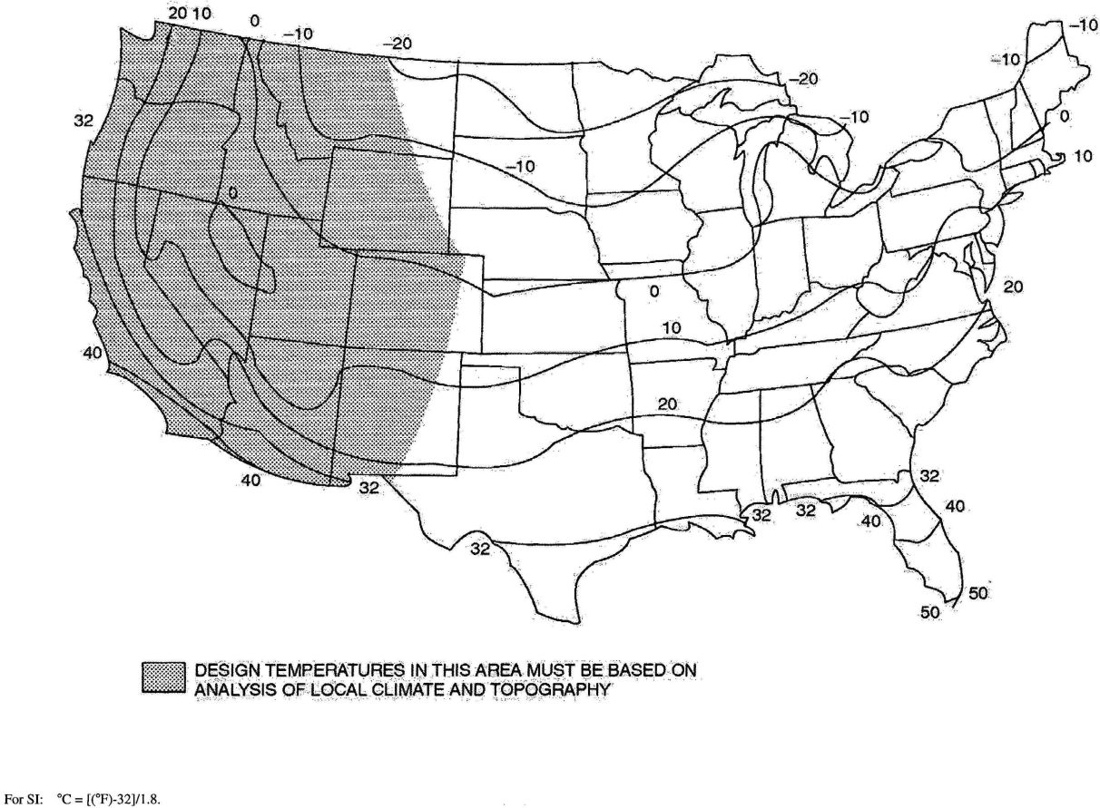
FIGURE R301.2(1)
ISOLINES OF THE 97½ PERCENT WINTER (DECEMBER, JANUARY AND FEBRUARY) DESIGN TEMPERATURES (°F)
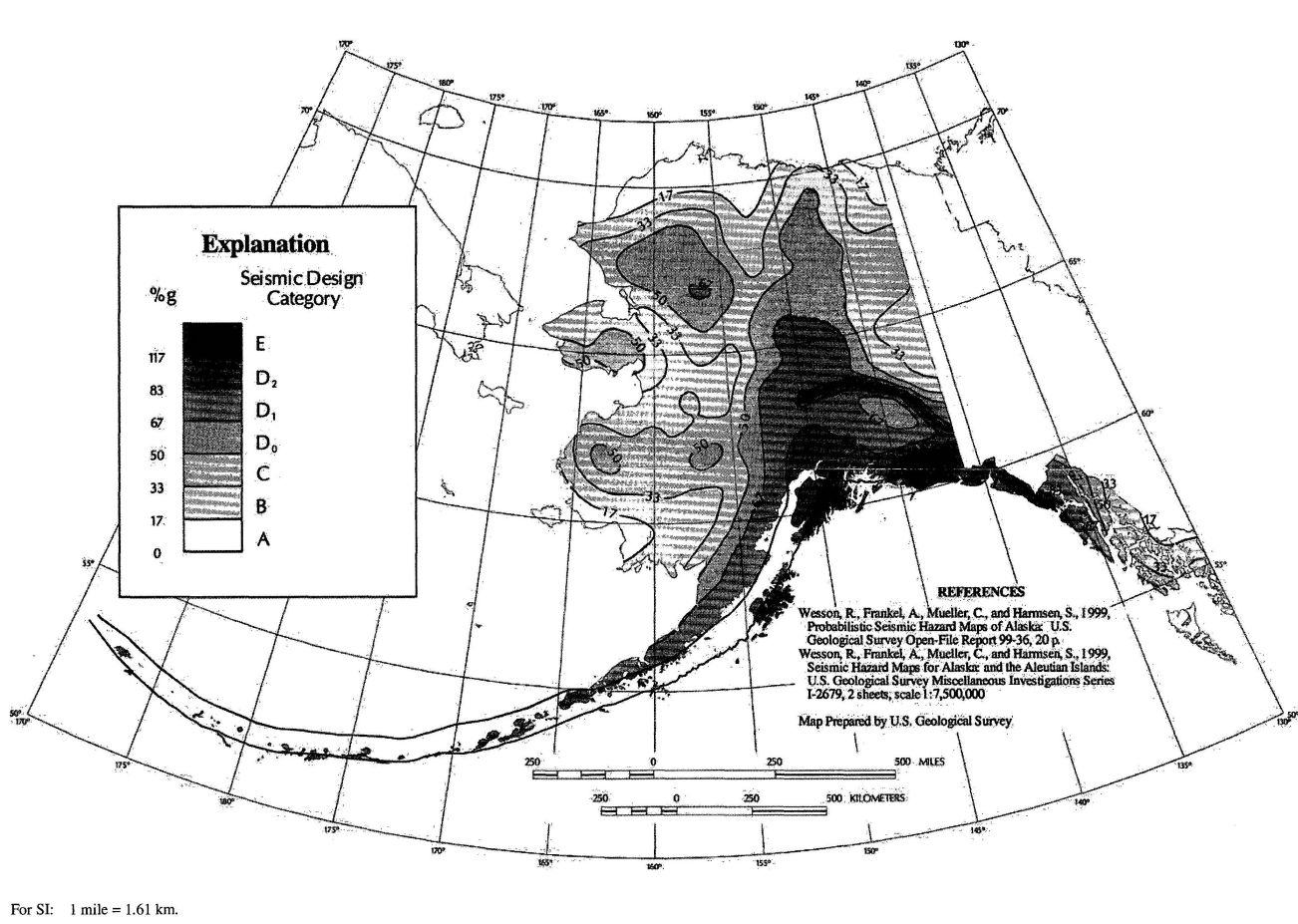
FIGURE R301.2(2)
SEISMIC DESIGN CATEGORIES—SITE CLASS D
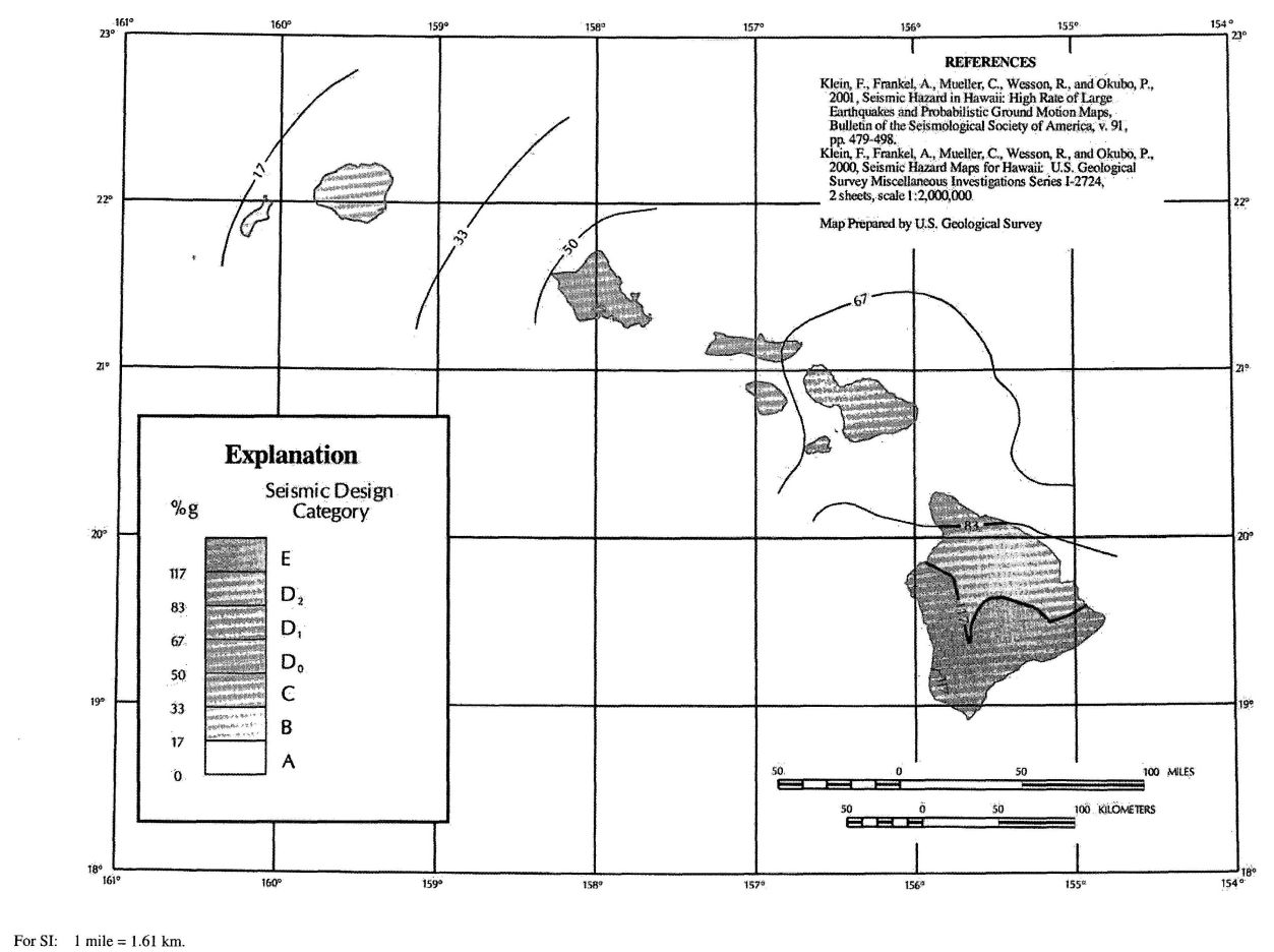
FIGURE R301.2(2)—continued
SEISMIC DESIGN CATEGORIES—SITE CLASS D
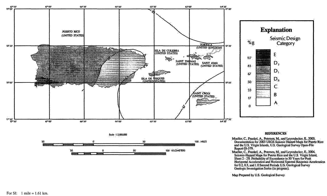
FIGURE R301.2(2)—continued
SEISMIC DESIGN CATEGORIES—SITE CLASS D
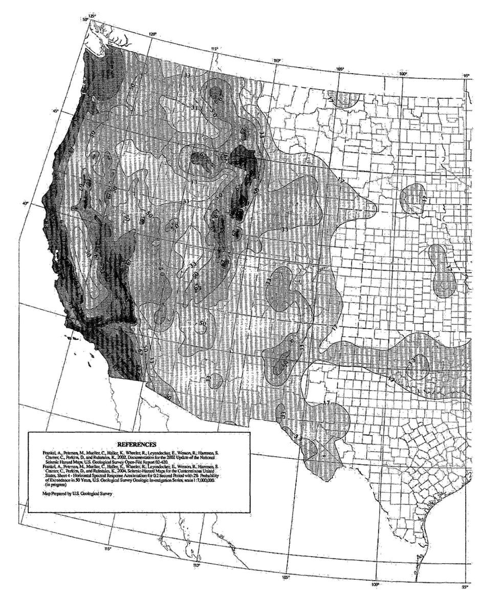
FIGURE R301.2(2)—continued
SEISMIC DESIGN CATEGORIES—SITE CLASS D
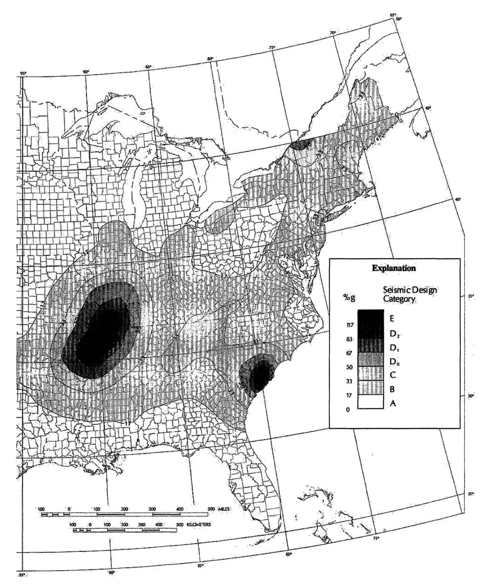
FIGURE R301.2(2)—continued
SEISMIC DESIGN CATEGORIES—SITE CLASS D
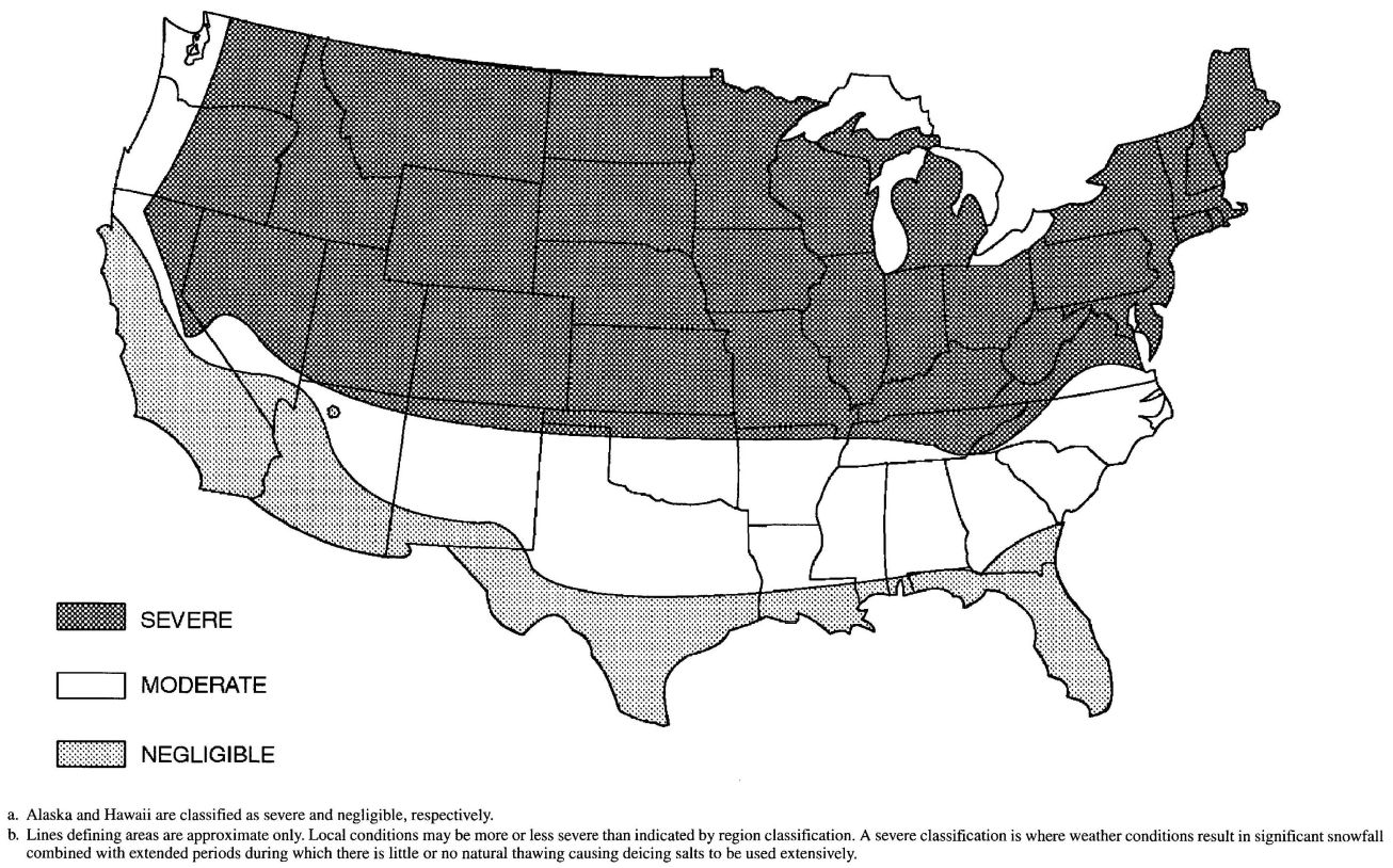
FIGURE R301.2(3)
WEATHERING PROBABILITY MAP FOR CONCRETE
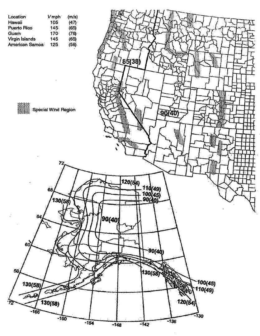
FIGURE R301.2(4)
BASIC WIND SPEEDS FOR 50-YEAR MEAN RECURRENCE INTERVAL
For SI: 1 foot = 304.8 mm, 1 mile per hour = 0.447 m/s.
a. Values are nominal design 3-second gust wind speeds in miles per hour at 33 feet above ground for Exposure C category.
b. Linear interpolation between wind contours is permitted.
c. Islands and coastal areas outside the last contour shall use the last wind speed contour of the coastal area.
d. Mountainous terrain, gorges, ocean promontories and special wind regions shall be examined for unusual wind conditions.
e. Enlarged view of Eastern and Southern seaboards are on the following pages.
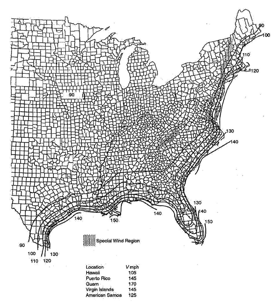
FIGURE R301.2(4)—continued
BASIC WIND SPEEDS FOR 50-YEAR MEAN RECURRENCE INTERVAL
For SI: 1 foot = 304.8 mm, 1 mile per hour = 0.447 m/s.
a. Values are nominal design 3-second gust wind speeds in miles per hour at 33 feet above ground for Exposure C category.
b. Linear interpolation between wind contours is permitted.
c. Islands and coastal areas outside the last contour shall use the last wind speed contour of the coastal area.
d. Mountainous terrain, gorges, ocean promontories and special wind regions shall be examined for unusual wind conditions.
e. Enlarged view of Eastern and Southern seaboards are on the following pages.
54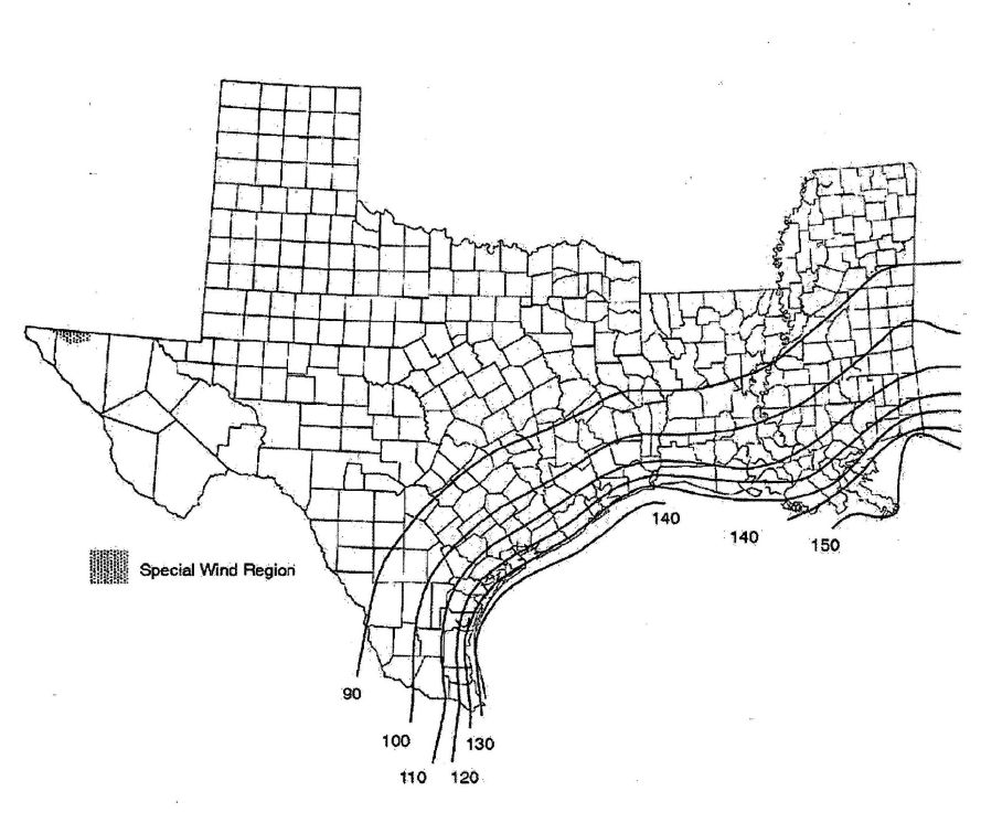
FIGURE R301.2(4)—continued
BASIC WIND SPEEDS FOR 50-YEAR MEAN RECURRENCE INTERVAL
For SI: 1 foot = 304.8 mm, 1 mile per hour = 0.447 m/s.
a. Values are nominal design 3-second gust wind speeds in miles per hour at 33 feet above ground for Exposure C category.
b. Linear interpolation between wind contours is permitted.
c. Islands and coastal areas outside the last contour shall use the last wind speed contour of the coastal area.
d. Mountainous terrain, gorges, ocean promontories and special wind regions shall be examined for unusual wind conditions.
55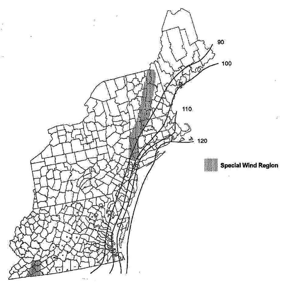
FIGURE R301.2(4)—continued
BASIC WIND SPEEDS FOR 50-YEAR MEAN RECURRENCE INTERVAL
For SI: 1 foot = 304.8 mm, 1 mile per hour = 0.447 m/s.
a. Values are nominal design 3-second gust wind speeds in miles per hour at 33 feet above ground for Exposure C category.
b. Linear interpolation between wind contours is permitted.
c. Islands and coastal areas outside the last contour shall use the last wind speed contour of the coastal area.
d. Mountainous terrain, gorges, ocean promontories and special wind regions shall be examined for unusual wind conditions.
56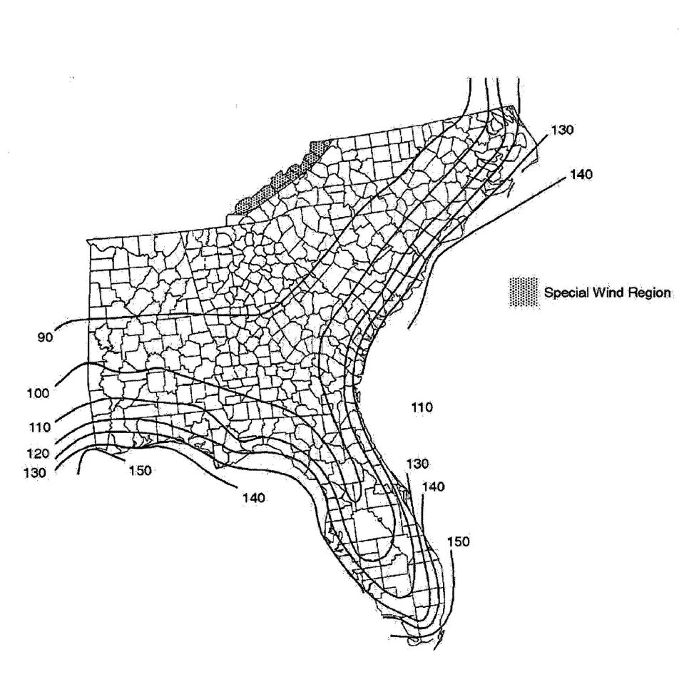
FIGURE R301.2(4)—continued
BASIC WIND SPEEDS FOR 50-YEAR MEAN RECURRENCE INTERVAL
For SI: 1 foot = 304.8 mm, 1 mile per hour = 0.447 m/s.
a. Values are nominal design 3-second gust wind speeds in miles per hour at 33 feet above ground for Exposure C category.
b. Linear interpolation between wind contours is permitted.
c. Islands and coastal areas outside the last contour shall use the last wind speed contour of the coastal area.
d. Mountainous terrain, gorges, ocean promontories and special wind regions shall be examined for unusual wind conditions.
57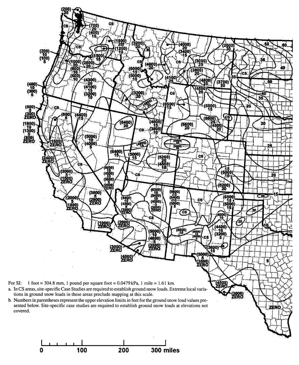
FIGURE R301.2(5)
GROUND SNOW LOADS, Pg, FOR THE UNITED STATES (lb/ft2)
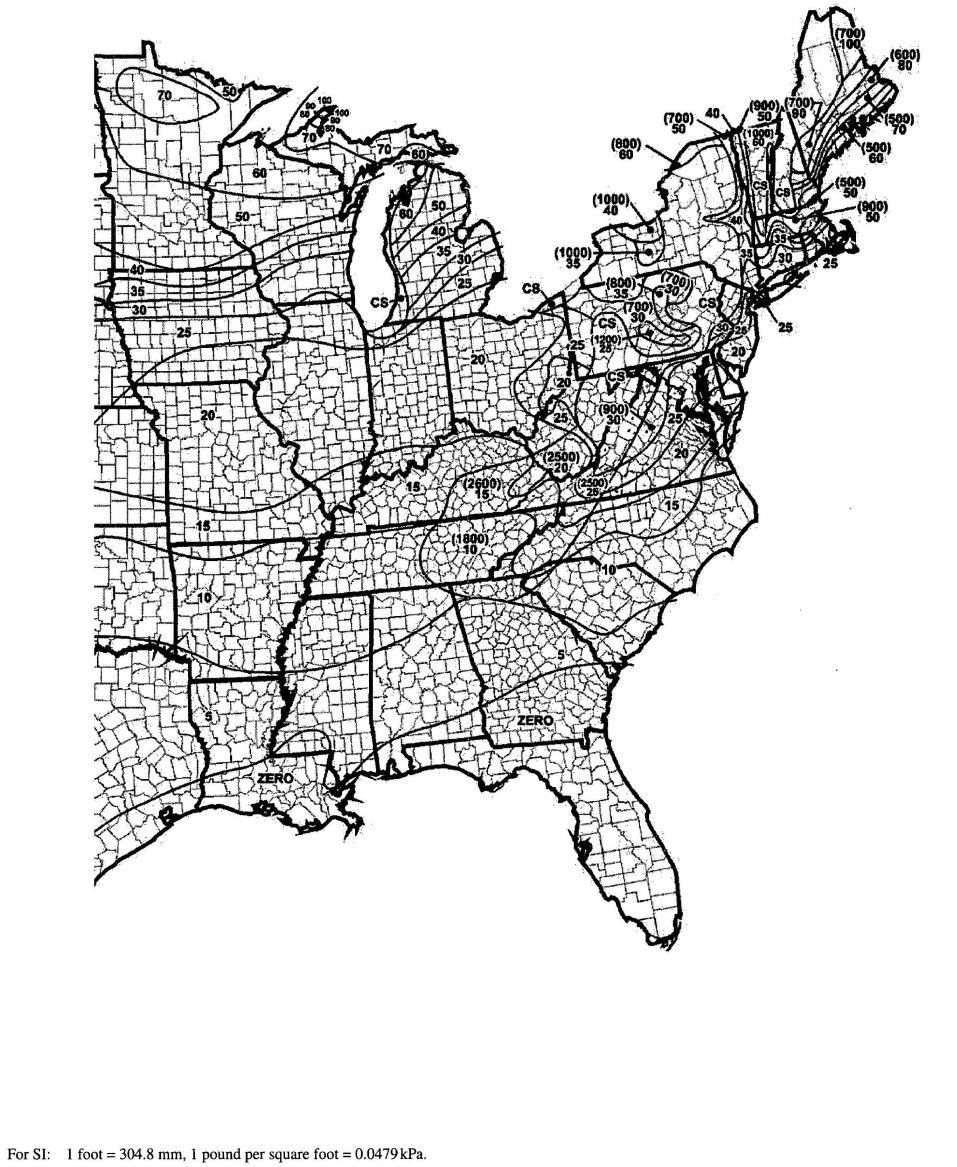
FIGURE R301.2(5)—continued
GROUND SNOW LOADS, Pg, FOR THE UNITED STATES (lb/ft2)
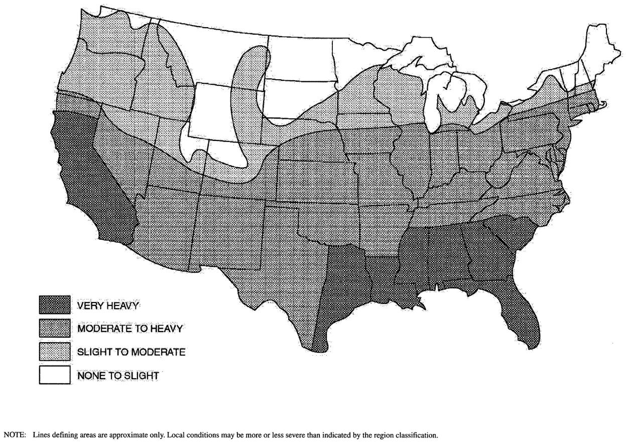
FIGURE R301.2(6)
TERMINTE INFESTATION PROBABILITY MAP
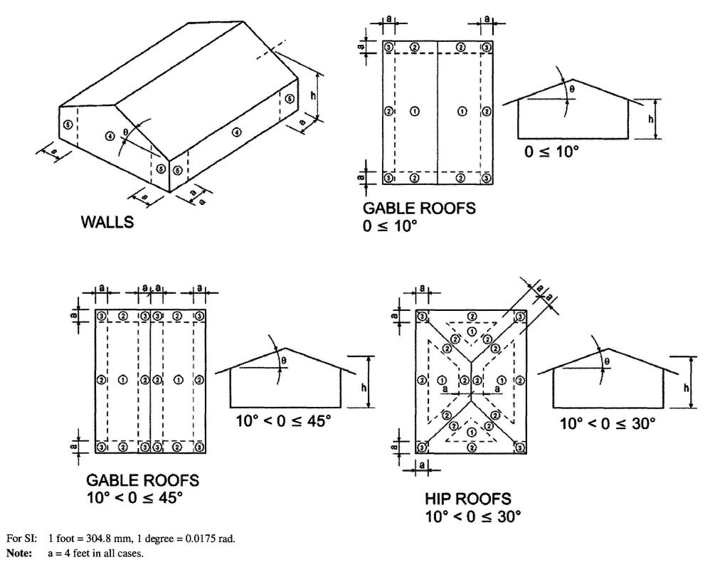
FIGURE R301.2(7)
COMPONENTAND CLADDING PRESSURE ZONES
R301.2.1.3 Wind speed conversion. When referenced documents are based on fastest mile wind speeds, the three-second gust basic wind speeds, V3s, of Figure R301.2(4) shall be converted to fastest mile wind speeds, Vfm, using Table R301.2.1.3.
R301.2.1.4 Exposure category. For each wind direction considered, an exposure category that adequately reflects the characteristics of ground surface irregularities shall be determined for the site at which the building or structure is to be constructed. For a site located in the transition zone between categories, the category resulting in the largest wind forces shall apply. Account shall be taken of variations in ground surface roughness that arise from natural topography and vegetation as well as from constructed features. For a site where multiple detached one- and two-family dwellings, townhouses or other structures are to be constructed as part of a subdivision, master-planned community, or otherwise designated as a developed area by the authority having jurisdiction, the exposure category for an individual structure shall be based upon the site conditions that will exist at the time when all adjacent structures on the site have been constructed, provided their construction is expected to begin within one year of the start of construction for the structure for which the exposure category is determined. For any given wind direction, the exposure in which a specific building or other structure is sited shall be assessed as being one of the following categories:
R301.2.1.5 Topographic wind effects. In areas designated in Table R301.2(1) as having local historical data documenting structural damage to buildings caused by wind speed-up at isolated hills, ridges and escarpments that are abrupt changes from the general topography of the area, topographic wind effects shall be considered in the design of the building in accordance with Section R301.2.1.5.1 or in accordance with the provisions of ASCE 7. See Figure R301.2.1.5.1(1) for topographic features for wind speed-up effect.
In these designated areas, topographic wind effects shall apply only to buildings sited on the top half of an isolated hill, ridge or escarpment where all of the following conditions exist:
R301.2.1.5.1 Simplified topographic wind speed-up method. As an alternative to the ASCE 7 topographic wind provisions, the provisions of Section R301.2.1.5.1 shall be permitted to be used to design for wind speed-up effects, where required by Section R301.2.1.5.
Structures located on the top half of isolated hills, ridges or escarpments meeting the conditions of Section R301.2.1.5 shall be designed for an increased basic wind speed as determined by Table R301.2.1.5.1. On the high side of an escarpment, the increased basic wind speed shall extend horizontally downwind from the edge of the escarpment 1.5 times the horizontal length of the upwind slope (1.5L) or 6 times the height of the escarpment (6H), whichever is greater. See Figure R301.2.1.5.1(2) for where wind speed increase is applied.
R301.2.2 Seismic provisions. The seismic provisions of this code shall apply to buildings constructed in Seismic Design Categories C, D0, D1 and D2, as determined in accordance with this section.
Exception: Detached one- and two-family dwellings located in Seismic Design Category C are exempt from the seismic requirements of this code.
| For SI: 1 mile per hour = 0.447 m/s. | |||||||||||||
| a. Linear interpolation is permitted. | |||||||||||||
| 3-second gust, V3s | 85 | 90 | 100 | 105 | 110 | 120 | 125 | 130 | 140 | 145 | 150 | 160 | 170 |
| Fastest mile, Vfm | 71 | 76 | 85 | 90 | 95 | 104 | 109 | 114 | 123 | 128 | 133 | 142 | 152 |
| BASIC WIND SPEED FROM FIGURE R301.2(4) (mph) | AVERAGE SLOPE OF THE TOP HALF OF HILL, RIDGE OR ESCARPMENT (percent) | ||||||
|---|---|---|---|---|---|---|---|
| 0.10 | 0.125 | 0.15 | 0.175 | 0.20 | 0.23 | 0.25 or greater | |
| Required basic wind speed-up, modified for topographic wind speed up (mph) | |||||||
| For SI: 1 mile per hour = 0.447 m/s. | |||||||
| 85 | 100 | 100 | 100 | 110 | 110 | 110 | 120 |
| 90 | 100 | 100 | 110 | 110 | 120 | 120 | 120 |
| 100 | 110 | 120 | 120 | 130 | 130 | 130 | 140 |
| 110 | 120 | 130 | 130 | 140 | 140 | 150 | 150 |
| 120 | 140 | 140 | 150 | 150 | N/A | N/A | N/A |
| 130 | 150 | N/A | N/A | N/A | N/A | N/A | N/A |
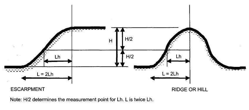
FIGURE R301.2.1.5.1(1)
TOPOGRAPHIC FEATURES FOR WIND SPEED-UP EFFECT
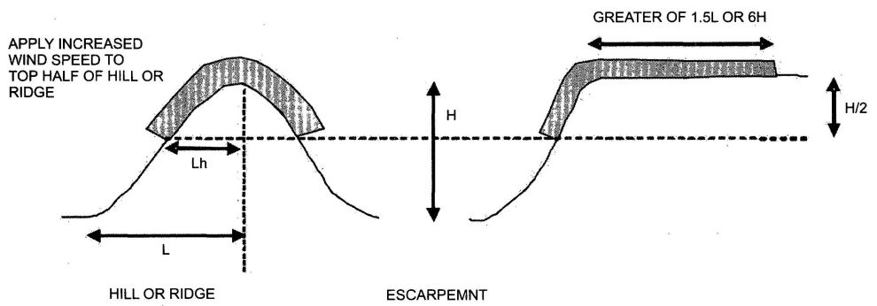
FIGURE R301.2.1.5.1(2)
ILLUSTRATION OF WHERE ON A TOPOGRAPHIC FEATURE, WIND SPEED INCREASE IS APPLIED
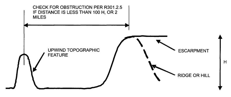
FIGURE R301.2.1.5.1(3)
ILLUSTRATION OF WHERE ON A TOPOGRAPHIC FEATURE, WIND SPEED INCREASE IS APPLIED
R301.2.2.1 Determination of seismic design category. Buildings shall be assigned a seismic design category in accordance with Figure R301.2(2).
R301.2.2.1.1 Alternate determination of seismic design category. The Seismic Design Categories and corresponding Short Period Design Spectral Response Accelerations, SDS shown in Figure R301.2(2) are based on soil Site Class D, as defined in Section 1613.5.2 of the California Building Code. If soil conditions are other than Site Class D, the Short Period Design Spectral Response Accelerations, SDS, for a site can be determined according to Section 1613.5 of the California Building Code. The value of SDS determined according to Section 1613.5 of the California Building Code is permitted to be used to set the seismic design category according to Table R301.2.2.1.1, and to interpolate between values in Tables R602.10.1, R603.7 and other seismic design requirements of this code.
| CALCULATED SDS | SEISMIC DESIGN CATEGORY |
|---|---|
| SDS≤0.17g | A |
| 0.17g<SDS≤0.33g | B |
| 0.33g<SDS≤0.50g | C |
| 0.50g<SDS≤0.67g | D0 |
| 0.67g<SDS≤0.83g | D1 |
| 0.83g<SDS≤1.17g | D2 |
| 1.17g<SDS | E |
R301.2.2.1.2 Alternative determination of Seismic Design Category E. Buildings located in Seismic Design Category E in accordance with Figure R301.2(2) are permitted to be reclassified as being in Seismic Design Category D2 provided one of the following is done:
R301.2.2.2 Seismic Design Category C. Structures assigned to Seismic Design Category C shall conform to the requirements of this section.
R301.2.2.2.1 Weights of materials. Average dead loads shall not exceed 15 pounds per square foot (720 Pa) for the combined roof and ceiling assemblies (on a horizontal projection) or 10 pounds per square foot (480 Pa) for floor assemblies, except as further limited by Section R301.2.2. Dead loads for walls above grade shall not exceed:
Exceptions:
- Roof and ceiling dead loads not exceeding 25 pounds per square foot (1190 Pa) shall be permitted provided the wall bracing amounts in Chapter 6 are increased in accordance with Table R301.2.2.2.1.
- Light-frame walls with stone or masonry veneer shall be permitted in accordance with the provisions of Sections R702.1 and R703.
- Fireplaces and chimneys shall be permitted in accordance with Chapter 10.
| WALL SUPPORTING | ROOF/CEILING DEAD LOAD | |
|---|---|---|
| 15 psf or less | 25 psf | |
| For SI: 1 pound per square foot = 0.0479 kPa. | ||
| a. Linear interpolation shall be permitted. | ||
| Roof only | 1.0 | 1.2 |
| Roof plus one or two stories | 1.0 | 1.1 |
R301.2.2.2.2 Stone and masonry veneer. Anchored stone and masonry veneer shall comply with the requirements of Sections R702.1 and R703.
R301.2.2.2.3 Masonry construction. Masonry construction shall comply with the requirements of Section R606.11.2.
R301.2.2.2.4 Concrete construction. Detached one- and two-family dwellings with exterior above-grade concrete walls shall comply with the requirements of Section R611, PCA 100 or shall be designed in accordance with ACI 318. Townhouses with above-grade exterior concrete walls shall comply with the requirements of PCA 100 or shall be designed in accordance with ACI 318.
R301.2.2.2.5 Irregular buildings. Prescriptive construction as regulated by this code shall not be used for irregular structures located in Seismic Design Categories C, D0, D1 and D2. Irregular portions of structures shall be designed in accordance with accepted engineering practice to the extent the irregular features affect the performance of the remaining structural system. When the forces associated with the irregularity are resisted by a structural system designed in accordance with accepted engineering practice, design of the remainder of the building shall be permitted using the provisions of this code. A building or portion of a building shall be considered to be irregular when one or more of the following conditions occur:
Exception: For wood light-frame construction, floors with cantilevers or setbacks not exceeding four times the nominal depth of the wood floor joists are permitted to support braced wall panels that are out of plane with braced wall panels below provided that:
- Floor joists are nominal 2 inches by 10 inches (51 mm by 254 mm) or larger and spaced not more than 16 inches (406 mm) on center.
- The ratio of the back span to the cantilever is at least 2 to 1.
- Floor joists at ends of braced wall panelsare doubled.
- For wood-frame construction, a continuous rim joist is connected to ends of all cantilever joists. When spliced, the rim joists shall be spliced using a galvanized metal tie not less than 0.058 inch (1.5 mm) (16 gage) and 1½ inches (38 mm) wide fastened with six 16d nails on each side of the splice or a block of the same size as the rim joist of sufficient length to fit securely between the joist space at which the splice occurs fastened with eight 16d nails on each side of the splice; and
- Gravity loads carried at the end of cantilevered joists are limited to uniform wall and roof loads and the reactions from headers having a span of 8 feet (2438 mm) or less.
Exception: Portions of floors that do not support shear walls or braced wall panels above, or roofs, shall be permitted to extend no more than 6 feet (1829 mm) beyond a shear wall or braced wall line.
Exception: For wood light-frame wall construction, one end of a braced wall panel shall be permitted to extend more than 1 foot (305 mm) over an opening not more than 8 feet (2438 mm) wide in the wall below provided that the opening includes a header in accordance with the following:
- The building width, loading condition and framing member species limitations of Table R502.5(1) shall apply; and
- Not less than one 2x12 or two 2x10 for an opening not more than 4 feet (1219 mm) wide; or
- Not less than two 2x12 or three 2x10 for an opening not more than 6 feet (1829 mm) wide; or
- Not less than three 2x12 or four 2x10 for an opening not more than 8 feet (2438 mm) wide; and
- The entire length of the braced wall panel does not occur over an opening in the wall below.
Exceptions:
- Framing supported directly by continuous foundations at the perimeter of the building.
- For wood light-frame construction, floors shall be permitted to be vertically offset when the floor framing is lapped or tied together as required by Section R502.6.1.
Exception: Fireplaces, chimneys and masonry vencer as permitted by this code. When this irregularity applies, the entire story shall be designed in accordance with accepted engineering practice.
R301.2.2.3 Seismic Design Categories D0, D1 and D2. Structures assigned to Seismic Design Categories D0, D1, and D2 shall conform to the requirements for Seismic Design Category C and the additional requirements of this section.
R301.2.2.3.1 Height limitations. Wood framed buildings shall be limited to three stories above grade or the limits given in Table R602.10.1.2(2). Cold-formed steel framed buildings shall be limited to less than or equal to three stories above grade in accordance with AISI S230. Mezzanines as defined in Section R202 shall not be considered as stories. Structural insulated panel buildings shall be limited to two stories above grade.
R301.2.2.3.2 Stone and masonry veneer. Anchored stone and masonry veneer shall comply with the requirements of Sections R702.1 and R703.
R301.2.2.3.3 Masonry construction. Masonry construction in Seismic Design Categories D0 and D1 shall comply with the requirements of Section R606.11.3. Masonry construction in Seismic Design Category D2 shall comply with the requirements of Section R606.11.4.
R301.2.2.3.4 Concrete construction. Buildings with exterior above-grade concrete walls shall comply with PCA 100 or shall be designed in accordance with ACI 318.
R301.2.2.3.5 Cold-formed steel framing in Seismic Design Categories D0, D1 and D2. In Seismic Design Categories D0, D1 and D2 in addition to the requirements of this code, cold-formed steel framing shall comply with the requirements of AISI S230.
R301.2.2.3.6 Masonry chimneys. Masonry chimneys shall be reinforced and anchored to the building in accordance with Sections R1003.3 and R1003.4.
R301.2.2.3.7 Anchorage of water heaters. Water heaters shall be anchored against movement and over-turning in accordance with the California Plumbing Code.
R301.2.2.4 Seismic Design Category E. Buildings in Seismic Design Category E shall be designed in accordance with the California Building Code, except when the seismic design category in accordance with Section R301.2.2.1.
R301.2.3 Snow loads. Wood framed construction, cold-formed steel framed construction and masonry and concrete construction, and structural insulated panel construction in regions with ground snow loads 70 pounds per square foot (3.35 kPa) or less, shall be in accordance with Chapters 5, 6 and 8. Buildings in regions with ground snow loads greater than 70 pounds per square foot (3.35 kPa) shall be designed in accordance with accepted engineering practice.
R301.2.4 Floodplain construction. Buildings and structures constructed in whole or in part in flood hazard areas (including A or V Zones) as established in Table R301.2.(1)
66shall be designed and constructed in accordance with Section R322.
Exception: Buildings and structures located in whole or in part in identified floodways shall be designed and constructed in accordance with ASCE 24.
R301.2.4.1 Alternative provisions. As an alternative to the requirements in Section R322.3 for buildings and structures located in whole or in part in coastal high hazard areas (V Zones), ASCE 24 is permitted subject to the limitations of this code and the limitations therein.
R301.3 Story height. Buildings constructed in accordance with these provisions shall be limited to story heights of not more than the following:
Exception: For wood framed wall buildings with bracing in accordance with Tables R602.10.1.2(1) and R602.10.1.2(2), the wall stud clear height used to determine the maximum permitted story height may be increased to 12 feet (3658 mm) without requiring an engineered design for the building wind and seismic force resisting systems provided that the length of bracing required by Table R602.10.1.2(1) is increased by multiplying by a factor of 1.10 and the length of bracing required by Table R602.10.1.2(2) is increased by multiplying by a factor of 1.20. Wall studs are still subject to the requirements of this section.
Exception: An additional 8 feet (2438 mm) is permitted for gable end walls.
Individual walls or walls studs shall be permitted to exceed these limits as permitted by Chapter 6 provisions, provided story heights are not exceeded. Floor framing height shall be permitted to exceed these limits provided the story height does not exceed 11 feet 7 inches (3531 mm). An engineered design shall be provided for the wall or wall framing members when they exceed the limits of Chapter 6. Where the story height limits are exceeded, an engineered design shall be provided in accordance with the California Building Code for the overall wind and seismic force resisting systems.
R301.4 Dead load. The actual weights of materials and construction shall be used for determining dead load with consideration for the dead load of fixed service equipment.
R301.5 Live load The minimum uniformly distributed live load shall be as provided in Table R301.5.
| USE | LIVE LOAD |
|---|---|
| For SI: 1 pound per square foot = 0.0479 kpa, 1 square inch = 645 mm², 1 pound=4.45 N. | |
| a. Elevated garage floors shall be capable of supporting a 2,000-pound load applied over a 20-square-inch area. | |
| b. Attics without storage are those where the maximum clear height between joist and after is less than 42 inches, or where there are not two or more adjacent trusses with the same web configuration capable of containing a rectangle 42 inches high by 2 feet wide, or greater, located within the plane of the truss. For attics without storage, this live load need not be assumed to act concurrently with any other live load requirements. | |
| c. Individual stair treads shall be designed for the uniformly distributed live load or a 300-pound concentrated load acting over an area of 4 square inches, whichever produces the greater stresses. | |
| d. A single concentrated load applied in any direction at any point along the top. | |
| e. See Section R502.2.2 for decks attached to exterior walls. | |
| f. Guard in-fill components (all those except the handrail), balusters and panel fillers shall be designed to withstand a horizontally applied normal load of 50 pounds on an area equal to 1 square foot. This load need not be assumed to act concurrently with any other live load requirement. | |
| g. For attics with limited storage and constructed with trusses, This live load need be applied only to those portions of the bottom chord where there are two or more adjacent trusses with the same web configuration capable of containing a rectangle 42 inches high or greater by 2 feet wide or greater, located within the plane of the truss.The rectangles shall fit between the top of the bottom chord and the bottom of any truss member, provided that each of the following criteria is met. | |
| 1. The attic area is accessible by a pull-down stairway or framed in accordance with Section R807.1. | |
| 2. The truss has a bottom chord pitch less than 2:12. | |
| 3. Required instulation depth is less than the bottom chord member depth. | |
| The bottom chords of trusses meeting the above criteria for limited storage shall be designed for the greater of the actual imposed dead load or 10 psf, uniformly distributed over the entire span. | |
| h. Glazing used in handrail assemblies and guards shall be designed with a safety factor of 4. The safety factor shall be applied to each of the concentrated loads applied to the top of the rail, and to the load on the in-fill components. These loads shall be determined independent of one another, and loads are assumed not to occur with any other live load. | |
| Attics without storageb | 10 |
| Attics with limited storageb,g | 20 |
| Habitable attics and attics served with fixed stairs |
30 |
| Balconies (exterior) and deckse | 40 |
| Fire escapes | 40 |
| Guardrails and handrailsd | 200h |
| Guardrail in-fill componentsf | 50h |
| Passenger vehicle garagesa | 50a |
| Rooms other than sleeping room | 40 |
| Sleeping rooms | 30 |
| Stairs | 40c |
R301.6 Roof load. The roof shall be designed for the live load indicated in Table R301.6 or the snow load indicated in Table R301.2(1), whichever is greater.
| ROOF SLOPE | TRIBUTARY LOADED AREA IN SQUARE FEET FOR ANY STRUCTURAL MEMBER | ||
|---|---|---|---|
| 0 to 200 | 201 to 600 | Over 600 | |
| For SI: 1 square foot=0.0929 m2, 1 pound per square foot=0.0479 kPa, 1 inch per foot=83.3 mm/m. | |||
| Flat or rise less than 4 inches per foot (1:3) |
20 | 16 | 12 |
| Rise 4 inches per foot (1:3) to less than 12 inches per foot (1:1) |
16 | 14 | 12 |
| Rise 12 inches per foot (1:1) and greater |
12 | 12 | 12 |
R301.7 Deflection. The allowable deflection of any structural member under the live load listed in Sections R301.5 and R301.6 shall not exceed the values in Table R301.7.
| STRUCTURAL MEMBER | ALLOWABLE DEFLECTION |
|---|---|
| Note: L=span length, H=span height. | |
| a. The wind load shall be permitted to be taken as 0.7 times the Component and Cladding loads for the purpose of the determining deflection limits herein. | |
| b. For cantilever members, L shall be taken as twice the length of the cantilever. | |
| c. For aluminum structural members or panel used in roofs or walls of sunroom additions or patio covers, not supporting edge of glass or sandwich panels, the total load deflection shall not exceed L/60. For continuous aluminum structural members supporting edge of glass, the total load deflection shall not exceed L/175 for each glass lite or L/60 for the entire length of the member, whichever is more stringent. For sandwich panels used in roofs or walls of sunroom additions or patio covers, the total load deflection shall not exceed L/120. | |
| d. Deflection for exterior walls with interior gypsum board finish shall be limited to an allowable deflection of H/180. | |
| e. Refer to Section R703.7.2. | |
| Rafters having slopes greater than 3:12 with no finished ceiling attached to rafters | L/180 |
| Interior walls and partitions | H/180 |
| Floors and plastered ceilings | L/360 |
| All other structural members | L/240 |
| Exterior walls with plaster or stucco finish | H/360 |
| Exterior walls—wind loadsa with brittle finishes | H/240 |
| Exterior walls—wind loadsa with flexible finishes |
L/120d |
| Lintels supporting masonry veneer wallse | L/600 |
R301.8 Nominal sizes. For the purposes of this code, where dimensions of lumber are specified, they shall be deemed to be nominal dimensions unless specifically designated as actual dimensions.
R302.1 Exterior walls. Construction, projections, openings and penetrations of exterior walls of dwellings and accessory buildings shall comply with Table R302.1(1); or for dwellings and accessory buildings equipped throughout with an automatic residential fire sprinkler system installed in accordance with Section R313 shall comply with Table R302.1(2).
Exceptions:
- Walls, projections, openings or penetrations in walls perpendicular to the line used to determine the fire separation distance.
- Walls of dwellings and accessory structures located on the same lot.
- Detached tool sheds and storage sheds, playhouses and similar structures exempted from permits are not required to provide wall protection based on location on the lot. Projections beyond the exterior wall shall not extend over the lot line.
- Detached garages accessory to a dwelling located within 2 feet (610 mm) of a lot line are permitted to have roof eave projections not exceeding 4 inches (102 mm).
- Foundation vents installed in compliance with this code are permitted.
R302.2 Townhouses. Each townhouse shall be considered a separate building and shall be separated by fire-resistance-rated wall assemblies meeting the requirements of Section R302.1 for exterior walls.
Exception: A common 1-hour fire-resistance-rated wall assembly tested in accordance with ASTME 119 or UL 263 is permitted for townhouses if such walls do not contain plumbing or mechanical equipment, ducts or rated for fire exposure from both sides and shall extend to and be tight against exterior walls and the underside of the roof sheathing. Electrical installations shall be installed in accordance with the California Electrical Code. Penetrations of electrical outlet boxes shall be in accordance with Section R302.4.
R302.2.1 Continuity. The fire-resistance-rated wall or assembly separating townhouses shall be continuous from the foundation to the underside of the roof sheathing, deck or slab. The fire-resistance rating shall extend the full length of the wall or assembly, including wall extensions through and separating attached enclosed accessory structures.
R302.2.2 Parapets. Parapets constructed in accordance with Section R302.2.3 shall be constructed for townhouses as an extension of exterior walls or common walls in accordance with the following:
Exception: A parapet is not required in the two cases above when the roof is covered with a minimum class C roof covering, and the roof decking or sheathing is of noncombustible materials or approved fire-retardant-treated wood for a distance of 4 feet (1219 mm) on each side of the wall or walls, or one layer of 5/8-inch (15.9 mm) Type X gypsum board is installed directly beneath the roof decking or sheathing, supported by a minimum of nominal 2-inch (51 mm) ledgers attached to the sides of the roof framing members, for a minimum distance of 4 feet (1219 mm) on each side of the wall or walls.
R302.2.3 Parapet construction. Parapets shall have the same fire-resistance rating as that required for the supporting wall or walls. On any side adjacent to a roof surface, the parapet shall have noncombustible faces for the uppermost 18 inches (457 mm), to include counterflashing and coping materials. Where the roof slopes toward a parapet at slopes greater than 2 units vertical in 12 units horizontal (16.7-percent slope), the parapet shall extend to the same height as any portion of the roof with in a distance of 3 feet (914 mm), but in no case shall the height be less than 30 inches (762 mm).
R302.2.4 Structural independence. Each individual townhouse shall be structurally independent.
Exceptions:
- Foundations supporting exterior walls or common walls.
- Structural roof and wall sheathing from each unit may fasten to the common wall framing.
- Nonstructural wall and roof coverings.
- Flashing at termination of roof covering over common wall.
- Townhouses separated by a common 1-hour fire-resistance-rated wall as provided in Section R302.2.
R302.3 Two-family dwellings. Dwelling units in two-family dwellings shall be separated from each other by wall and/or floor assemblies having not less than a 1-hour fire-resistance rating when tested in accordance with ASTME 119 or UL 263. Fire-resistance-rated floor-ceiling and wall assemblies shall extend to and be tight against the exterior wall, and wall assemblies shall extend from the foundation to the underside of the roof sheathing.
Exceptions:
- A fire-resistance rating of ½ hour shall be permitted in buildings equipped throughout with an automatic sprinkler system installed in accordance with NFPA 13.
- Wall assemblies need not extend through attic spaces when the ceiling is protected by not less than 5/8-inch (15.9 mm) Type X gypsum board and an attic draft stop constructed as specified in Section R302.12.1 is provided above and along the wall assembly separating the dwellings. The structural framing supporting the ceiling shall also be protected by not less than ½-inch (12.7 mm) gypsum board or equivalent.
R302.3.1 Supporting construction. When floor assemblies are required to be fire-resistance rated by Section R302.3, the supporting construction of such assemblies shall have an equal or greater fire-resistance rating.
R302.4 Dwelling unit rated penetrations. Penetrations of wall of floor/ceiling assemblies required to be fire-resistance rated in accordance with Section R302.2 or R302.3 shall be protected in accordance with this section.
| EXTERIOR WALL ELEMENT | MINIMUM FIRE-RESISTANCE RATING | MINIMUM FIRE SEPARATION DISTANCE | |
|---|---|---|---|
| For SI: 1 foot = 304.8 mm. | |||
| N/A=Not Applicable. | |||
| Walls | (Fire-resistance rated) | 1 hour-tested in accordance with ASTME 119 or UL 263 with exposure from both sides | < 5 feet |
| (Not fire-resistance rated) | 0 hours | ≥ 5 feet | |
| Projections | (Fire-resistance rated) | 1 hour on the underside | ≥ 2 feet to 5 feet |
| (Not fire-resistance rated) | 0 hours | 5 feet | |
| Openings in walls | Not allowed | N/A | < 3 feet |
| 25% maximum of wall area | 0 hours | 3 feet | |
| Unlimited | 0 hours | 5 feet | |
| Penetrations | All | Comply with Section R302.4 | < 5 feet |
| None required | 5 feet | ||
| EXTERIOR WALL ELEMENT | MINIMUM FIRE-RESISTANCE RATING | MINIMUM FIRE SEPARATION DISTANCE | |
|---|---|---|---|
| For SI: 1 foot = 304.8 mm. | |||
| N/A=Not Applicable. | |||
| Walls | (Fire-resistance rated) | 1 hour-tested in accordance with ASTME 119 or UL 263 with exposure from both sides | <3 feet |
| (Not fire-resistance rated) | 0 hours | >3 feet | |
| Projections | (Fire-resistance rated) | 1 hour on the underside | ≥2 feet to 3 feet |
| (Not fire-resistance rated) | 0 hours | 3 feet | |
| Openings in walls | Not allowed | N/A | < 3 feet |
| Unlimited | 0 hours | 3 feet | |
| Penetrations | All | Comply with Section R302.4 | < 3 feet |
| None required | 3 feet | ||
R302.4.1 Through penetrations. Through penetrations of fire-resistance-rated wall or floor assemblies shall comply with Section R302.4.1.1 or R302.4.1.2.
Exception: Where the penetrating items are steel, ferrous or copper pipes, tubes or conduits, the annular space shall be protected as follows:
- In concrete or masonry wall or floor assemblies, concrete, grout or mortar shall be permitted where installed to the full thickness of the wall or floor assembly or the thickness required to maintain the fire-resistance rating, provided:
- The nominal diameter of the penetrating item is a maximum of 6 inches (152 mm); and
- The area of the opening through the wall does not exceed 144 square inches (92 900 mm 2)
- The material used to fill the annular space shall prevent the passage of flame and hot gases sufficient to ignite cotton waste where subjected to ASTME 119 or UL 263 time temperature fire conditions under a minimum positive pressure differential of 0.01 inch of water (3 Pa) at the location of the penetration for the time period equivalent to the fire resistance rating of the construction penetrated.
R302.4.1.1 Fire-resistance-rated assembly. Penetrations shall be installed as tested in the approved fire-resistance-rated assembly.
R302.4.1.2 Penetration fire stop system. Penetrations shall be protected by an approved penetration firestop system installed as tested in accordance with ASTM E 814 or UL 1479, with a minimum positive pressure differential of 0.01 inch of water (3 Pa) and shall have an F rating of not less than the required fire-resistance rating of the wall or floor/ceiling assembly penetrated.
R302.4.2 Membrane penetrations. Membrane penetrations shall comply with Section R302.4.1. Where walls are required to have a fire-resistance rating, recessed fixtures shall be installed so that the required fire-resistance rating will not be reduced.
Exceptions:
- Membrane penetrations of maximum 2-hour fire-resistance-rated walls and partitions by steel electrical boxes that do not exceed 16 square inches (0.0103 m2) in area provided the aggregate area of the openings through the membrane does not exceed 100 square inches (0.0645 m2) in any 100 square feet (9.29 m2) of wall area. The annular space between the wall membrane and the box shall not exceed 1/8 inch (3.1 mm). Such boxes on opposite sides of the wall shall be separated by one of the following:
- By a horizontal distance of not less than 24 inches (610 mm) where the wall or partition is constructed with individual noncommunicating stud cavities;
- By a horizontal distance of not less than the depth of the wall cavity when the wall cavity is filled with cellulose loose-fill, rockwool or slag mineral wool insulation;
- By solid fire blocking in accordance with Section R302.11;
- By protecting both boxes with listed putty pads; or
- By other listed other materials and methods.
- Membrane penetrations by listed electrical boxes of any materials provided the boxes have been tested for use in fire-resistance-rated assemblies and are installed in accordance with the instructions included in the listing. The annular space between the wall membrane and the box shall not exceed 1/8 inch (3.1 mm) unless listed otherwise. Such boxes on opposite sides of the wall shall be separated by one of the following:
- The annular space created by the penetration of a fire sprinkler provided it is covered by a metal escutcheon plate.
R302.5 Dwelling/garage opening/penetration protection.Openings and penetrations through the walls or ceilings separating the dwelling from the garage shall be in accordance with Sections R302.5.1 through R302.5.3.
R302.5.1 Openings protection.Openings from a private garage directly into a room used for sleeping purposes shall not be permitted. Other openings between the garage and residence shall be equipped with solid wood doors not less than 1 3⁄8 inches (35 mm) in thickness, solid or honey comb core steel doors not less than 13⁄8; inches (35 mm) thick, or 20-minute fire-rated doors. Doors shall be self-closing and self -latching.
Exception: Where the residence and the private garage are protected by an automatic residential fire sprinkler system in accordance with Sections R309.6 and R313, other door openings between the private garage and the residence need only be self-closing and self-latching. This exception shall not apply to rooms used for sleeping purposes.
R302.5.2 Duct penetration. Ducts in the garage and ducts penetrating the walls or ceilings separating the dwelling from the garage shall be constructed of a minimum No. 26 gage (0.48 mm) sheet steel or other approved material and shall have no openings into the garage.
R302.5.3 Other penetrations. Penetrations through the separation required in Section R309.2 shall be protected as required by Section R302.1.1, Item 4.
R302.6 Dwelling garage and or carport fire separation.The garage and/or carport shall be separated as required by Table R302.6. Openings in garage walls shall comply with Section R302.5. This provision does not apply to garage walls that are perpendicular to the adjacent dwelling unit wall. A separation is not required between the dwelling unit and a carport, provided the carport is entirely open on two or more sides and there are not enclosed areas above.
R302.7 Under-stair protection. Enclosed accessible space under stairs shall have walls, under-stair surface and any soffits protected on the enclosed side with ½-inch (12.7 mm) gypsum board.
R302.8 Foam plastics. For requirements for foam plastics see Section R316.
R302.9 Flame spread index and smoke-developed index for wall and ceiling finishes. Flame spread and smoke index for wall and ceiling finishes shall be in accordance with Sections R302.9.1 through R302.9.4.
R302.9.1 Flame spread index. Wall and ceiling finishes shall have a flame spread index of not greater than 200.
Exception: Flame spread index requirements for finishes shall not apply to trim defined as picture molds, chair rails, baseboards and handrails; to doors and windows or their frames; or to materials that are less than 1⁄28 inch (0.91 mm) in thickness cemented to the surface of walls or ceilings if these materials exhibit flame spread index values no greater than those of paper of this thickness cemented to a noncombustible backing.
R302.9.2 Smoke-developed index. Wall and ceiling finishes shall have a smoke-developed index of not greater than 450.
R302.9.3 Testing. Tests shall be made in accordance with ASTME 84 or UL 723.
R302.9.4 Alternate test method. As an alternate to having a flame-spread index of not greater than 200 and a smoke developed index of not greater than 450 when tested in accordance with ASTM E 84 or UL 723, wall and ceiling finishes, other than textiles, shall be permitted to be tested in accordance with NFPA 286. Materials tested in accordance with NFPA 286 shall meet the following criteria:
During the 40 kW exposure, the interior finish shall comply with Item 1. During the 160 kW exposure, the interior finish shall comply with Item 2. During the entire test, the interior finish shall comply with Items 3 and 4 .
| SEPARATION | MATERIAL |
|---|---|
| For SI: 1 inch = 25.4 mm, 1 foot = 304.8 mm. | |
| From the residence and attics | Not less than½-inch gypsum board or equivalent applied to the garage side |
| From all habitable rooms above the garage or carport | Not less than 5⁄8-inch Type X gypsum board or equivalent |
| Structure(s) supporting floor/ceiling assemblies used for separation required by this section | Not less than ½-inch gypsum board or equivalent |
| Garages located less than 3 feet from a dwelling unit on the same lot | Not less than ½-inch gypsum board or equivalent applied to the interior side of exterior walls that are within this area |
R302.9.5 Stability. Interior finish materials regulated by this chapter shall be applied or otherwise fastened in such a manner that such materials will not readily become detached where subjected to room temperatures of 200°F (93°C) for not less than 30 minutes.
R302.10 Flame spread index and smoke developed index for insulation. Flame spread and smoke developed index for insulation shall be in accordance with Sections R302.10.1 through R302.10.5.
R302.10.1 Insulation. Insulation materials, including facings, such as vapor retarders and vapor-permeable membranes installed within floor-ceiling assemblies, roof-ceiling assemblies, wall assemblies, crawl spaces and attics shall have a flame spread index not to exceed 25 with an accompanying smoke-developed index not to exceed 450 when tested in accordance with ASTM E 84 or UL 723.
Exceptions:
- When such materials are installed in concealed spaces, the flame spread index and smoke-developed index limitations do not apply to the facings, provided that the facing is installed in substantial contact with the unexposed surface of the ceiling, floor or wall finish.
- Cellulose loose-fill insulation, which is not spray applied, complying with the requirements of Section R302.10.3, shall only be required to meet the smoke-developed index of not more than 450.
R302.10.2 Loose-fill insulation. Loose-fill insulation materials that cannot be mounted in the ASTM E 84 or UL 723 apparatus without a screen or artificial supports shall comply with the flame spread and smoke-developed limits of Section R302.10.1 when tested in accordance with CAN/ULC S102.2.
Exception: Cellulose loose-fill insulation shall not be required to be tested in accordance with CAN/ULC S102.2, provided such insulation complies with the requirements of Section R302.10.1 and Section R302.10.3.
R302.10.3 Cellulose loose-fill insulation. Cellulose loose-fill insulation shall comply with CPSC 16 CFR, Parts 1209 and 1404. Each package of such insulating material shall be clearly labeled in accordance with CPSC 16 CFR, Parts 1209 and 1404.
R302.10.4 Exposed attic insulation. All exposed insulation materials installed on attic floors shall have a critical radiant flux not less than 0.12 watt per square centimeter.
R302.10.5 Testing. Tests for critical radiant flux shall be made in accordance with ASTM E 970.
R302.11 Fire blocking. In combustible construction, fireblocking shall be provided to cut off all concealed draft openings (both vertical and horizontal) and to form an effective fire barrier between stories, and between a top story and the roof space.
Fireblocking shall be provided in wood-frame construction in the following locations:
R302.11.1 Fireblocking materials. Except as provided in Section R302.11, Item 4, fireblocking shall consist of the following materials.
R302.11.1.1 Batts or blankets of mineral or glass fiber. Batts or blankets of mineral or glass fiber or other approved nonrigid materials shall be permitted for compliance with the 10-foot (3048 mm) horizontal fireblocking in walls constructed using parallel rows of studs or staggered studs.
72R302.11.1.2 Unfaced fiberglass. Unfaced fiberglass batt insulation used as fireblocking shall fill the entire cross section of the wall cavity to a minimum height of 16 inches (406 mm) measured vertically. When piping, conduit or similar obstructions are encountered, the insulation shall be packed tightly around the obstruction.
R302.11.1.3 Loose-fill insulation material. Loose-fill insulation material shall not be used as a fireblock unless specifically tested in the form and manner intended for use to demonstrate its ability to remain in place and to retard the spread of fire and hot gases.
R302.11.2 Fireblocking integrity. The integrity of all fireblocks shall be maintained.
R302.12 Draftstopping. In combustible construction where there is usable space both above and below the concealed space of a floor/ceiling assembly, draftstops shall be installed so that the area of the concealed space does not exceed 1,000 square feet (92.9 m2). Draftstopping shall divide the concealed space into approximately equal areas. Where the assembly is enclosed by a floor membrane above and a ceiling membrane below, draftstopping shall be provided in floor/ceiling assemblies under the following circumstances:
R302.12.1 Materials. Draftstopping materials shall not be less than ½-inch (12.7 mm) gypsum board, 3⁄8-inch (9.5 mm) wood structural panels or other approved materials adequately supported. Draftopping shall be installed parallel to the floor framing members unless otherwise approved by the building official. The integrity of the draftstops shall be maintained.
R302.13 Combustible insulation clearance. Combustible insulation shall be separated a minimum of 3 inches (76 mm) from recessed luminaires, fan motors and other heat-producing devices.
Exception: Where heat-producing devices are listed for lesser clearances, combustible insulation complying with the listing requirements shall be separated in accordance with the conditions stipulated in the listing.
Recessed luminaires installed in the building envelope shall meet or exceed the requirements specified in the California Energy Code for recessed luminaires installed in insulated ceilings.
R303.1 Habitable rooms. All habitable rooms shall have an aggregate glazing area of not less than 8 percent of the floor area of such rooms . Natural ventilation shall be through windows, doors, louvers or other approved openings to the outdoor air. Such openings shall be provided with ready access or shall other wise be readily controllable by the building occupants. The minimum openable area to the outdoors shall be 4 percent of the floor area being ventilated.
Exceptions:
- The glazed areas need not be openable where the opening is not required by Section R310 and an approved mechanical ventilation system capable of producing 0.35 air change per hour in the room is installed or a whole-house mechanical ventilation system is installed capable of supplying outdoor ventilation air of 15 cubic feet per minute (cfm) (78 L/s) per occupant computed on the basis of two occupants for the first bedroom and one occupant for each additional bedroom.
- The glazed areas need not be installed in rooms where Exception 1 above is satisfied and artificial light is provided capable of producing an average illumination of 6 footcandles (65 lux) over the area of the room at a height of 30 inches (762 mm) above the floor level.
- Use of sunroom additions and patio covers, as defined in Section R202, shall be permitted for natural ventilation if in excess of 40 percent of the exterior sunroom walls are open, or are enclosed only by insect screening.
- The windows, doors, louvers and other approved closeable openings not required by Section R310 may open into a passive solar energy collector for ventilation required by this section. The area of ventilation openings to the outside of the passive solar energy collector shall be increased to compensate for the openings required by the interior space.
- Glazed openings may open into a passive solar energy collector provided the area of exterior glazed opening(s) into the passive solar energy collector is increased to compensate for the area required by the interior space.
R303.2 Adjoining rooms. For the purpose of determining light and ventilation requirements, any room shall be considered as a portion of an adjoining room when at least one-half of the area of the common wall is open and unobstructed and provides an opening of not less than one-tenth of the floor area of the interior room but not less than 25 square feet (2.3 m2).
Exception: Openings required for light and/or ventilation shall be permitted to open into a thermally isolated sunroom addition or patio cover, provided that there is an openable area between the adjoining room and the sunroom addition or patio cover of not less than one-tenth of the floor area of the interior room but not less than 20 square feet (2 m2). The minimum openable area to the outdoors shall be based upon the total floor area being ventilated.
R303.3 Bathrooms. Bathrooms, water closet compartments and other similar rooms shall be provided with aggregate glazing area in windows of not less than 3 square feet (0.3 m2), one-half of which must be openable.
73Exception: The glazed areas shall not be required where artificial light and a mechanical ventilation system are provided. The minimum ventilation rates shall be 50 cubic feet per minute (24 L/s) for intermittent ventilation or 25 cubic feet per minute (12 L/s) for continuous ventilation. Ventilation air from the space shall be exhausted directly to the outside.
R303.4 Opening location. Outdoor intake and exhaust openings shall be located in accordance with Sections R303.4.1 and R303.4.2.
R303.4.1 Intake openings. Mechanical and gravity outdoor air intake openings shall be located a minimum of 10 feet (3048 mm) from any hazardous or noxious contaminant, such as vents, chimneys, plumbing vents, streets, alleys, parking lots and loading docks, except as otherwise specified in this code. Where a source of a contaminant is located within 10 feet (3048 mm) of an intake opening, such opening shall be located a minimum of 2 feet (610 mm) below the contaminant source.
For the purpose of this section, the exhaust from dwelling unit toilet rooms, bathrooms and kitchens shall not be considered as hazardous or noxious.
R303.4.2 Exhaust openings. Exhaust air shall not be directed onto walkways.
R303.5 Outside opening protection. Air exhaust and intake openings that terminate outdoors shall be protected with corrosion-resistant screens, louvers or grilles having a minimum opening size of ¼inch (6 mm) and a maximum opening size of ½ inch (13 mm), in any dimension. Openings shall be protected against local weather conditions. Outdoor air exhaust and intake openings shall meet the provisions for exterior wall opening protectives in accordance with this code.
R303.6 Stairway illumination. All interior and exterior stairways shall be provided with a means to illuminate the stairs, including the landings and treads. Interior stairways shall be provided with an artificial light source located in the immediate vicinity of each landing of the stairway. For interior stairs the artificial light sources shall be capable of illuminating treads and landings to levels not less than 1 foot-candle (11 lux) measured at the center of treads and landings. Exterior stairways shall be provided with an artificial light source located in the immediate vicinity of the top landing of the stairway. Exterior stairways providing access to a basement from the outside grade level shall be provided with an artificial light source located in the immediate vicinity of the bottom landing of the stairway.
Exception: An artificial light source is not required at the top and bottom landing, provided an artificial light source is located directly over each stairway section.
R303.6.1 Light activation. Where lighting outlets are installed in interior stairways, there shall be a wall switch at each floor level to control the lighting outlet where the stairway has six or more risers. The illumination of exterior stairways shall be controlled from inside the dwelling unit.
Exception: Lights that are continuously illuminated or automatically controlled.
R303.7 Required glazed openings. Required glazed openings shall open directly onto a street or public alley, or a yard or court located on the same lot as the building.
Exceptions:
- Required glazed openings may face into a roofed porch where the porch abuts a street, yard or court and the longer side of the porch is at least 65 percent unobstructed and the ceiling height is not less than 7 feet (2134 mm).
- Eave projections shall not be considered as obstructing the clear open space of a yard or court.
- Required glazed openings may face into the area under a deck, balcony, bay or floor cantilever provided a clear vertical space at least 36 inches (914 mm) in height is provided.
- Glazed openings covered by a passive solar energy collector in accordance with Section R303.1, Exception 5.
R303.7.1 Sunroom additions. Required glazed openings shall be permitted to open into sunroom additions or patio covers that abut a street, yard or court if in excess of 40 percent of the exterior sunroom walls are open, or are enclosed only by insect screening, and the ceiling height of the sunroom is not less than 7 feet (2134 mm).
R303.7.1.1 Passive solar energy collectors. When a passive solar energy collector is designed as a conditioned area it shall comply with the California Energy Code, Title 24, Part 6. Nonconditioned passive solar energy collectors are exempt from Title 24, Part 6.
R303.8 Required heating. When the winter design temperature in Table R301.2(1) is below 60°F (16°C), every dwelling unit shall be provided with heating facilities capable of maintaining a minimum room temperature of 68°F (20°C) at a point 3 feet (914 mm) above the floor and 2 feet (610 mm) from exterior walls in all habitable rooms at the design temperature. The installation of one or more portable space heaters shall not be used to achieve compliance with this section.
Note: See Section R301.1.1.1 for limited-density owner-built rural dwellings.
R304.1 Minimum area. Every dwelling unit shall have at least one habitable room that shall have not less than 120 square feet (11 m2) of gross floor area.
R304.2 Other rooms. Other habitable rooms shall have a floor area of not less than 70 square feet (6.5 m2).
Exception: Kitchens.
R304.3 Minimum dimensions. Habitable rooms shall not be less than 7 feet (2134 mm) in any horizontal dimension.
Exceptions:
- Kitchens.
- Limited-density owner-built rural dwellings. See Section R301.1.1.1.
R304.4 Height effect on room area. Portions of a room with a sloping ceiling measuring less than 5 feet (1524 mm) or a furred ceiling measuring less than 7 feet (2134 mm) from the finished floor to the finished ceiling shall not be considered as contributing to the minimum required habitable area for that room.
74R305.1 Minimum height. Habitable space, hallways, bathrooms, toilet rooms, laundry rooms and portions of basements containing these spaces shall have a ceiling height of not less than 7 feet (2134 mm).
Exceptions:
- For rooms with sloped ceilings, at least 50 percent of the required floor area of the room must have a ceiling height of at least 7 feet (2134 mm) and no portion of the required floor area may have a ceiling height of less than 5 feet (1524 mm).
- Bathrooms shall have a minimum ceiling height of 6 feet 8 inches (2032 mm) at the center of the front clearance area for fixtures as shown in Figure R307.1. The ceiling height above fixtures shall be such that the fixture is capable of being used for its intended purpose. A shower or tub equipped with a showerhead shall have a minimum ceiling height of 6 feet 8 inches (2032 mm) above a minimum area 30 inches (762 mm) by 30 inches (762 mm) at the showerhead.
R305.1.1 Basements. Portions of basements that do not contain habitable space, hallways, bathrooms, toilet rooms and laundry rooms shall have a ceiling height of not less than 6 feet 8 inches (2032 mm).
Exception:Beams, girders, ducts or other obstructions may project to within 6 feet 4 inches (1931 mm) of the finished floor.
R306.1 Toilet facilities. Every dwelling unit shall be provided with a water closet, lavatory, and a bathtub or shower.
R306.2 Kitchen. Each dwelling unit shall be provided with a kitchen area and every kitchen area shall be provided with a sink.
R306.3 Sewage disposal. All plumbing fixtures shall be connected to a sanitary sewer or to an approved private sewage disposal system.
R306.4 Water supply to fixtures. All plumbing fixtures shall be connected to an approved water supply. Kitchen sinks, lavatories, bathtubs, showers, bidets, laundry tubs and washing machine outlets shall be provided with hot and cold water.
R307.1 Space required. Fixtures shall be spaced in accordance with the California Plumbing Code.
R307.2 Bathtub and shower spaces. Bathtub and shower floors and walls above bathtubs with installed shower heads and in shower compartments shall be finished with a nonabsorbent surface. Such wall surfaces shall extend to a height of not less than 6 feet (1829 mm) above the floor.
R308.1 Identification. Except as indicated in Section R308.1.1 each pane of glazing installed in hazardous locations as defined in Section R308.4 shall be provided with a manufacturer’s designation specifying who applied the designation, designating the type of glass and the safety glazing standard with which it complies, which is visible in the final installation. The designation shall be acid etched, sandblasted, ceramic-fired, laser etched, embossed, or be of a type which once applied cannot be removed without being destroyed. A label shall be permitted in lieu of the manufacturer’s designation.
Exceptions:
- For other than tempered glass, manufactuer’s designations are not required provided the building official approves the use of a certificate, affidavit or other evidence confirming compliance with this code.
- Tempered spandrel glass is permitted to be identified by the manufacturer with a removable paper designation.
R308.1.1 Identification of multiple assemblies. Multipane assemblies having individual panes not exceeding 1 square foot (0.09 m2) in exposed area shall have at least one pane in the assembly identified in accordance with Section R308.1. All other panes in the assembly shall be labeled “CPSC 16 CFR 1201” or “ANSI Z97.1” as appropriate.
R308.2 Louvered windows or jalousies. Regular, float, wired or patterned glass in jalousies and louvered windows shall be no thinner than nominal 3⁄16 inch (5 mm) and no longer than 48 inches (1219 mm). Exposed glass edges shall be smooth.
R308.2.1 Wired glass prohibited.Wired glass with wire exposed on longitudinal edges shall not be used in jalousies or louvered windows.
R308.3 Human impact loads. Individual glazed areas, including glass mirrors in hazardous locations such as those indicated as defined in Section R308.4, shall pass the test requirements of Section R308.3.1.
Exceptions:
- Louvered windows and jalousies shall comply with Section R308.2.
- Mirrors and other glass panels mounted or hung on a surface that provides a continuous backing support.
- Glass unit masonry complying with Section R610.
R308.3.1 Impact test. Where required by other sections of the code, glazing shall be tested in accordance with CPSC 16 CFR 1201. Glazing shall comply with the test criteria for Category I or II as indicated in Table R308.3.1(1).
Exception: Glazing not in doors or enclosures for hot tubs, whirlpools, saunas, steam rooms, bathtubs and showers shall be permitted to be tested in accordance
75with ANSI Z97.1. Glazing shall comply with the test criteria for Class A or B as indicated in Table R308.3.1 (2).
R308.4 Hazardous locations. The following shall be considered specific hazardous locations for the purposes of glazing:
Exceptions:
- Glazed openings of a size through which a 3-inch diameter (76 mm) sphere is unable to pass.
- Decorative glazing.
Exceptions:
- Decorative glazing.
- When there is an intervening wall or other permanent barrier between the door and the glazing.
- Glazing in walls on the latch side of and perpendicular to the plane of the door in a closed position.
- Glazing adjacent to a door where access through the door is to a closet or storage area 3 feet (914 mm) or less in depth.
- Glazing that is adjacent to the fixed panel of patio doors.
Exceptions:
- Decorative glazing.
- When a horizontal rail is installed on the accessible side(s) of the glazing 34 to 38 inches (864 to 965) above the walking surface. The rail shall be capable of with-standing a horizontal load of 50 pounds per linear foot (730 N/m) without contacting the glass and be a minimum of 1½ inches (38 mm) in cross sectional height.
- Outboard panes in insulating glass units and other multiple glazed panels when the bottom edge of the glass is 25 feet (7620 mm) or more above grade, a roof, walking surfaces or other horizontal [within 45 degrees (0.79 rad) of horizontal] surface adjacent to the glass exterior.
| EXPOSED SURFACE AREA OF ONE SIDE OF ONE LITE | GLAZING IN STORM OR COMBINATION DOORS (Category Class) | GLAZING IN DOORS (Category Class) | GLAZED PANELS REGULATED BY ITEM 7 OF SECTION R308.4 (Category Class) | GLAZED PANELS REGULATED BY ITEM 6 OF SECTION R308.4 (Category Class) | GLAZING IN DOORS AND ENCLOSURES REGULATED BY ITEM 5 OF SECTION R308.4 (Category Class) | SLIDING GLASS DOORS PATIO TYPE (Category Class) |
|---|---|---|---|---|---|---|
| For SI:1 square foot=0.0929m2 | ||||||
| NR means “No Requirement” | ||||||
| 9 square feet or less | I | I | NR | I | II | II |
| More than 9 square feet | II | II | II | II | II | II |
| EXPOSED SURFACE AREA OF ONE SIDE OF ONE LITE | GLAZED PANELS REGULATED BY ITEM 7 OF SECTION R308.4 (Category Class) | GLAZED PANELS REGULATED BY ITEM 6 OF SECTION R308.4 (Category Class) | DOORS AND ENCLOSURES REGULATED BY ITEM 5 OF SECTION R308.4a (Category Class) |
|---|---|---|---|
| For SI: 1 Square foot = 0.0929 m2 | |||
| a. Use is permitted only by the exception to Section R308.3.1. | |||
| 9 square feet or less | No requirement | B | A |
| More than 9 square feet | A | A | A |
the bottom exposed edge of the glazing is less than 60 inches (1524 mm) measured vertically above any standing or walking surface.
Exception: Glazing that is more than 60 inches (1524 mm), measured horizontally and in a straight line, from the waters edge of a hot tub, whirlpool or bathtub.
Exceptions:
- When a rail is installed on the accessible side(s) of the glazing 34 to 38 inches (864 to 965 mm) above the walking surface. The rail shall be capable of with standing a horizontal load of 50 pounds per linear foot (730 N/m) without contacting the glass and be a minimum of 1½ inches (38 mm) in cross sectional height.
- The side of the stairway has a guardrail or hand-rail, including balusters or in-fill panels, complying with Sections R311.7.6 and R312 and the plane of the glazing is more than 18 inches (457 mm) from the railing; or
- When a solid wall or panel extends from the plane of the adjacent walking surface to 34 inches (863 mm) to 36 inches (914 mm) above the walking surface and the construction at the top of that wall or panel is capable of withstanding the same horizontal load as a guard.
Exceptions:
- The side of the stairway has a guardrail or hand-rail, including balusters or in-fill panels, complying with Sections R311.7.6 and R312 and the plane of the glass is more than 18 inches (457 mm) from the railing; or
- When a solid wall or panel extends from the plane of the adjacent walking surface to 34 inches (864 mm) to 36 inches (914 mm) above the walking surface and the construction at the top of that wall or panel is capable of withstanding the same horizontal load as a guard.
R308.5 Site built windows. Site built windows shall comply with Section 2404 of the California Building Code.
R308.6 Skylights and sloped glazing. Skylights and sloped glazing shall comply with the following sections.
R308.6.1 Definitions.
SKYLIGHTS AND SLOPED GLAZING. Glass or other transparent or translucent glazing material installed at a slope of 15 degrees (0.26 rad) or more from vertical. Glazing materials in skylights, including unit skylights, solariums, sunrooms, roofs and sloped walls are included in this definition.
UNIT SKYLIGHT. A factory assembled, glazed fenestration unit, containing one panel of glazing material, that allows for natural daylighting through an opening in the roof assembly while preserving the weather-resistant barrier of the roof.
R308.6.2 Permitted materials. The following types of glazing may be used:
R308.6.3 Screens, general. For fully tempered or heat-strengthened glass, a retaining screen meeting the requirements of Section R308.6.7 shall be installed below the glass, except for fully tempered glass that meets either condition listed in Section R308.6.5.
R308.6.4 Screens with multiple glazing. When the inboard pane is fully tempered, heat-strengthened or wired glass, a retaining screen meeting the requirements of Section R308.6.7 shall be installed below the glass, except for either condition listed in Section R308.6.5. All other panes in the multiple glazing may be of any type listed in Section. R308.6.2.
R308.6.5 Screens not required. Screens shall not be required when fully tempered glass is used as single glazing or the inboard pane in multiple glazing and either of the following conditions are met:
R308.6.6 Glass in greenhouses. Any glazing material is permitted to be installed without screening in the sloped areas of greenhouses, provided the greenhouse height at the ridge does not exceed 20 feet (6096 mm) above grade.
R308.6.7 Screen characteristics. The screen and its fastenings shall be capable of supporting twice the weight of the glazing, be firmly and substantially fastened to the framing members, and have a mesh opening of no more than 1 inch by 1 inch (25 mm by 25 mm).
R308.6.8 Curbs for skylights. All unit skylights installed in a roof with a pitch flatter than three units vertical in 12 units horizontal (25-percent slope) shall be mounted on a curb extending at least 4 inches (102 mm) above the plane of the roof unless otherwise specified in the manufacturer’s installation instructions.
R308.6.9 Testing and labeling. Unit skylights shall be tested by an approved independent laboratory, and bear a label identifying manufacturer, performance grade rating and approved inspection agency to indicate compliance with the requirements of AAMA/WDMA/CSA 101/I.S.2/A440.
R309.1 Floor surface. Garage floor surfaces shall be of approved noncombustible material.
The area of floor used for parking of automobiles or other vehicles shall be sloped to facilitate the movement of liquids to a drain or toward the main vehicle entry doorway.
R309.2 Carports. Carports shall be open on at least two sides. Carport floor surfaces shall be of approved noncombustible material. Carports not open on at least two sides shall be considered a garage and shall comply with the provisions of this section for garages.
Exception: Asphalt surfaces shall be permitted at ground level in carports.
The area of floor used for parking of automobiles or other vehicles shall be sloped to facilitate the movement of liquids to a drain or toward the main vehicle entry doorway.
R309.3 Flood hazard areas. For buildings located in flood hazard areas as established by Table R301.2(1), garage floors shall be:
R309.4 Automatic garage door openers. Automatic garage door openers, if provided, shall be listed in accordance with UL 325. See Health and Safety Code Sections 19890 and 19891 for additional provisions for residential garage door openers.
R309.5 Extension garage door springs. Every extension garage door spring sold or offered for sale, whether new or sold as a replacement, or installed in any garage or carport which is accessory to a dwelling covered by this code, shall conform to the requirements for garage door springs located in Section 1211 of the California Building Code.
R309.6 Fire sprinklers. Carports with habitable space above and attached garages shall be protected by residential fire sprinkler system in accordance with this section. Residential fire sprinklers shall be connected to, and installed in accordance with, a fire sprinkler system that complies with Section R313 or NFPA 13D. Fire sprinklers shall be residential sprinklers or quick-response sprinklers, designed to provide a minimum density of 0.05 gpm/ft2 (2.04 mm/min) over the area of the garage and/or carport, but not to exceed two sprinklers for hydraulic calculation purposes. Garage doors shall not be considered obstructions with respect to sprinkler placement.
Exception: An automatic residential fire sprinkler system shall not be required when additions or alterations are made to existing carports and/or garages that do not have an automatic residential fire sprinkler system installed in accordance with this section.
R310.1 Emergency escape and rescue required. Basements, habitable attics and every sleeping room shall have at least one operable emergency escape and rescue opening. Where basements contain one or more sleeping rooms, emergency, egress and rescue openings shall be required in each sleeping room. Where emergency escape and rescue openings are provided they shall have a sill height of not more than 44 inches (1118 mm) above the floor. Where a door opening having a threshold below the adjacent ground elevation serves as an emergency escape and rescue opening and is provided with a bulkhead enclosure, the bulkhead enclosure shall comply with Section R310.3. The net clear opening dimensions required by this section shall be obtained by the normal operation of the emergency escape and resuce openings from the inside. Emergency escape and rescue openings with a finished sill height below the adjacent ground elevation shall be provided with a window well in accordance with Section R310.2. Emergency escape and rescue openings shall open directly into a public way, or to a yard or court that opens to a public way.
Exception: Basements used only to house mechanical equipment and not exceeding total floor area of 200 square feet (18.58 m2).
R310.1.1 Minimum opening area. All emergency escape and rescue openings shall have a minimum net clear opening of 5.7 square feet (0.530 m2).
Exception: Grade floor openings shall have a minimum net clear opening of 5 square feet (0.465 m2).
R310.1.2 Minimum opening height. The minimum net clear opening height shall be 24 inches (610 mm).
R310.1.3 Minimum opening width. The minimum net clear opening width shall be 20 inches (508 mm).
R310.1.4 Operational constraints. Emergency escape and rescue openings shall be maintained free of any obstruct
78tions other than those allowed by this section and shall be operational from the inside of the room without the use of keys, tools or special knowledge.
R310.2 Window wells. The minimum horizontal area of the window well shall be 9 square feet (0.9 m2), with a minimum horizontal projection and width of 36 inches (914 mm). The area of the window well shall allow the emergency escape and rescue opening to be fully opened.
Exception: The ladder or steps required by Section R310.2.1 shall be permitted to encroach a maximum of 6 inches (152 mm) into the required dimensions of the window well.
R310.2.1 Ladder and steps. Window wells with a vertical depth greater than 44 inches (1118 mm) shall be equipped with a permanently affixed ladder or steps usable with the window in the fully open position. Ladders or steps required by this section shall not be required to comply with Sections R311.7 and R311.8. Ladders or rungs shall have an inside width of at least 12 inches (305 mm), shall project at least 3 inches (76 mm) from the wall and shall be spaced not more than 18 inches (457 mm) on center vertically for the full height of the window well.
R310.3 Bulkhead enclosures. Bulkhead enclosures shall provide direct access to the basement. The bulkhead enclosure with the door panels in the fully open position shall provide the minimum net clear opening required by Section R310.1.1. Bulkhead enclosures shall also comply with Section R311.7.8.2.
R310.4 Bars, grilles, covers and screens. Bars, grilles, covers, screens or similar devices are permitted to be placed over emergency escape and rescue openings, bulkhead enclosures, or window wells that serve such openings, provided the minimum net clear opening size complies with Sections R310.1.1 to R310.1.3, and such devices shall be releasable or removable from the inside without the use of a key, tool, special knowledge, or force greater than that which is required for normal operation of the escape and rescue opening. The release mechanism shall be maintained operable at all times.
Such bars, grills, grates or any similar devices shall be equipped with an approved exterior release device for use by the fire department only when required by the authority having jurisdiction.
Where security bars (burglar bars) are installed on emergency egress and rescue windows or doors, on or after July 1, 2000, such devices shall comply with California Building Standards Code, Part 12, Chapter 12-3 and other applicable provisions of this code.
R311.1 Means of egress. All dwellings shall be provided with a means of egress as provided in this section. The means of egress shall provide a continuous and unobstructed path of vertical and horizontal egress travel from all portions of the dwelling to the exterior of the dwelling at the required egress door without requiring travel through a garage.
R311.2 Egress door. At least one egress door shall be provided for each dwelling unit. The egress door shall be side-hinged, and shall provide a minimum clear width of 32 inches (813 mm) when measured between the face of the door and the stop, with the door open 90 degrees (1.57 rad). The minimum clear height of the door opening shall not be less than 78 inches (1981 mm) in height measured from the top of the threshold to the bottom of the stop. Other doors shall not be required to comply with these minimum dimensions. Egress doors shall be readily openable from inside the dwelling without the use of a key or special knowledge or effort.
R311.3 Floors and landings at exterior doors. There shall be a landing or floor on each side of each exterior door. The width of each landing shall not be less than the door served. Every landing shall have a minimum dimension of 36 inches (914 mm) measured in the direction of travel. Exterior landings shall be permitted to have a slope not to exceed ¼ unit vertical in 12 units horizontal (2-percent).
Exception: Exterior balconies less than 60 square feet (5.6 m2) and only accessible from a door are permitted to have a landing less than 36 inches (914 mm) measured in the direction of travel.
R311.3.1 Floor elevations at the required egress doors. Landings or floors at the required egress door shall not be more then 1½ inches (38 mm) lower than the top of the threshold.
Exception: The exterior landing or floor shall not be more than 7¾ inches (196 mm) below the top of the threshold provided the door does not swing over the landing or floor.
When exterior landings or floors serving the required egress door are not at grade, they shall be provided with access to grade by means of a ramp in accordance with Section R311.8 or a stairway in accordance with Section R311.7.
R311.3.2 Floor elevations for other exterior doors. Doors other than the required egress door shall be provided with landings or floors not more than 7¾ inches (196 mm) below the top of the threshold.
Exception: A landing is not required where a stairway of two or fewer risers is located on the exterior side of the door, provided the door does not swing over the stairway.
R311.3.3 Storm and screen doors. Storm and screen doors shall be permitted to swing over all exterior stairs and landings.
R311.4 Vertical egress. Egress from habitable levels including habitable attics and basements not provided with an egress door in accordance with Section R311.2 shall be by one or more ramps in accordance with Section R311.7 or both. For habitable levels or basements located more than one story above or more than one story below an egress door, the maximum travel distance from any occupied point to a stairway or ramp that provides egress from such habitable level or basement, shall not exceed 50 feet (15 240 mm).
R311.5 Construction.
R311.5.1 Attachment. Exterior landings, decks, balconies, stairs and similar facilities shall be positively anchored to
79the primary structure to resist both vertical and lateral forces or shall be designed to be self-supporting. Attachment shall not be accomplished by use of toenails or nails subject to withdrawal.
R311.6 Hallways. The minimum width of a hallway shall be not less than 3 feet (914 mm).
R311.7 Stairways.
R311.7.1 Width. Stairways shall not be less than 36 inches (914 mm) in clear width at all points above the permitted handrail height and below the required headroom height. Handrails shall not project more than 4.5 inches (114 mm) on either side of the stairway and the minimum clear width of the stairway at and below the handrail height, including treads and landings, shall not be less than 31½ inches (787 mm) where a handrail is installed on one side and 27 inches (698 mm) where handrails are provided on both sides.
Exception: The width of spiral stairways shall be in accordance with Section R311.7.9.1.
R311.7.2 Headroom. The minimum headroom in all parts of the stairway shall not be less than 6 feet 8 inches (2032 mm) measured vertically from the sloped line adjoining the tread nosing or from the floor surface of the landing or platform on that portion of the stairway.
Exception: Where the nosings of treads at the side of a flight extend under the edge of a floor opening through which the stair passes, the floor opening shall be allowed to project horizontally into the required headroom a maximum of 4¾ inches (121 mm).
R311.7.3 Walkline. The walkline across winder treads shall be concentric to the curved direction of travel through the turn and located 12 inches (305 mm) from the side where the winders are narrower. The 12-inch (305 mm) dimension shall be measured from the widest point of the clear stair width at the walking surface of the winder. If winders are adjacent within the flight, the point of the widest clear stair width of the adjacent winders shall be used.
R311.7.4 Stair treads and risers. Stair treads and risers shall meet the requirements of this section. For the purposes of this section all dimensions and dimensioned surfaces shall be exclusive of carpets, rugs or runners.
R311.7.4.1 Riser height. The maximum riser height shall be 7¾ inches (196 mm). The riser shall be measured vertically between leading edges of the adjacent treads. The greatest riser height within any flight of stairs shall not exceed the smallest by more than 3/8 inch (9.5 mm).
R311.7.4.2 Tread depth. The minimum tread depth shall be 10 inches (254 mm). The tread depth shall be measured horizontally between the vertical planes of the foremost projection of adjacent treads and at a right angle to the tread’s leading edge. The greatest tread depth within any flight of stairs shall not exceed the smallest by more than3/8 inch (9.5 mm). Consistently shaped winders at the walkline shall be allowed within the same flight of stairs as rectangular treads and do not have to be within 3/8 inch (9.5 mm) of the rectangular tread depth.
Winder treads shall have a minimum tread depth of 10 inches (254 mm) measured between the vertical planes of the foremost projection of adjacent treads at the intersections with the walkline. Winder treads shall have a minimum tread depth of 6 inches (152 mm) at any point within the clear width of the stair. Within any flight of stairs, the largest winder tread depth at the walkline shall not exceed the smallest winder tread by more than 3/8 inch (9.5 mm).
R311.7.4.3 Profile The radius of curvature at the nosing shall be no greater than 9/16 inch (14 mm). A nosing not less than ¾ inch (19 mm) but not more than 1¼ inches (32 mm) shall be provided on stairways with solid risers. The greatest nosing projection shall not exceed the smallest nosing projection by more than 3/8 inch (9.5 mm) between two stories, including the nosing at the level of floors and landings. Beveling of nosings shall not exceed ½ inch (12.7 mm). Risers shall be vertical or sloped under the tread above from the underside of the nosing above at an angle not more than 30 degrees (0.51 rad) from the vertical. Open risers are permitted, provided that the opening between treads does not permit the passage of a 4-inch diameter (102 mm) sphere.
Exceptions:
- A nosing is not required where the tread depth is a minimum of 11 inches (279 mm).
- The opening between adjacent treads is not limited on stairs with a total rise of 30 inches (762 mm) or less.
R311.7.4.4 Exterior wood/plastic composite stair treads. Wood/plastic composite stair treads shall comply with the provisions of Section R317.4.
R311.7.5 Landings for stairways. There shall be a floor or landing at the top and bottom of each stairway.
Exception: A floor or landing is not required at the top of an interior flight of stairs, including stairs in an enclosed garage, provided a door does not swing over the stairs. A flight of stairs shall not have a vertical rise larger than 12 feet (3658 mm) between floor levels or landings. The width of each landing shall not be less than the width of the stairway served. Every landing shall have a minimum dimension of 36 inches (914 mm) measured in the direction of travel.
R311.7.6 Stairway walking surface. The walking surface of treads and landings of stairways shall be sloped no steeper than one unit vertical in 48 inches horizontal (2-percent slope).
R311.7.7 Handrails. Handrails shall be provided on at least one side of each continuous run of treads or flight with four or more risers.
80R311.7.7.1 Height. Handrail height, measured vertically from the sloped plane adjoining the tread nosing, or finish surface of ramp slope, shall be not less than 34 inches (864 mm) and not more than 38 inches (965 mm).
Exceptions:
- The use of a volute, turnout or starting easing shall be allowed over the lowest tread.
- When handrail fittings or bendings are used to provide continuous transition between flights, the transition from handrail to guardrail, or used at the start of a flight, the handrail height at the fittings or bendings shall be permitted to exceed the maximum height.
R311.7.7.2 Continuity. Handrails for stairways shall be continuous for the full length of the flight, from a point directly above the top riser of the flight to a point directly above the lowest riser of the flight. Handrail ends shall be returned or shall terminate in newel posts or safety terminals. Handrail adjacent to a wall shall have a space of not less than 1½ inch (38 mm) between the wall and the handrails.
Exceptions:
- Handrails shall be permitted to be interrupted by a newel post at the turn.
- The use of a volute, turnover, starting easing or starting newel shall be allowed over the lowest tread.
R311.7.7.3 Grip-size. All required handrails shall be of one of the following types or provide equivalent graspability.
R311.7.7.4 Exterior wood/plastic composite handrails. Wood/plastic composite handrails shall comply with the provisions of Section R317.4.
R311.7.8 Illumination. All stairs shall be provided with illumination in accordance with Section R303.6.
R311.7.9 Special stairways. Spiral stairways and bulkhead enclosure stairways shall comply with all requirements of Section R311.7 except as specified below.
R311.7.9.1 Spiral stairways. Spiral stairways are permitted, provided the minimum clear width at and below the handrail shall be 26 inches (660 mm) with each tread having a 7½ inch (190 mm) minimum tread depth at 12 inches (914 mm) from the narrower edge. All treads shall be identical, and the rise shall be no more than 9½ inches (241 mm). A minimum headroom of 6 feet 6 inches (1982 mm) shall be provided.
R311.7.9.2 Bulkhead enclosure stairways. Stairways serving bulkhead enclosures, not part of the required building egress, providing access from the outside grade level to the basement shall be exempt from the requirements of Sections R311.3 and R311.7 where the maximum height from the basement finished floor level to grade adjacent to the stairway does not exceed 8 feet (2438 mm) and the grade level opening to the stairway is covered by a bulkhead enclosure with hinged doors or other approved means.
R311.8 Ramps.
R311.8.1 Maximum slope. Ramps shall have a maximum slope of 1 unit vertical in 12 units horizontal (8.3 percent slope).
Exception: Where it is technically infeasible to comply because of site constraints, ramps may have a maximum slope of one unit vertical in eight horizontal (12.5 percent slope).
R311.8.2 Landings required. A minimum 3-foot-by-3-foot (914 mm by 914 mm) landing shall be provided:
R311.8.3 Handrails required. Handrails shall be provided on at least one side of all ramps exceeding a slope of one unit vertical in 12 units horizontal (8.33-percent slope).
R311.8.3.1 Height. Handrail height, measured above the finished surface of the ramp slope, shall be not less than 34 inches (864 mm) and not more than 38 inches (965 mm).
R311.8.3.2 Grip size. Handrails on ramps shall comply with Section R311.7.7.3.
R311.8.3.3 Continuity. Handrails where required on ramps shall be continuous for the full length of the ramp. Handrail ends shall be returned or shall terminate in newel posts or safety terminals. Handrails adjacent to a wall shall have a space of not less than 1½ inches (38 mm) between the wall and the handrails.
R312.1 Where required. Guards shall be located along open-sided walking surfaces, including stairs, ramps and landings, that are located more than 30 inches (762 mm) measured vertically to the floor or grade below at any point within 36 inches (914 mm) horizontally to the edge of the open side. Insect screening shall not be considered as a guard.
R312.2 Height. Required guards at open-sided walking surfaces, including stairs, porches, balconies or landings, shall be not less than 42 inches (1067 mm) high measured vertically above the adjacent walking surface, adjacent fixed seating or the line connecting the leading edges of the treads.
Exceptions:
- Guards on the open sides of stairs shall have a height not less than 34 inches (864 mm) measured vertically from a line connecting the leading edges of the treads.
- Where the top of the guard also serves as handrail on the open sides of stairs, the top of the guard shall not be not less than 34 inches (864 mm) and not more than 38 inches (965 mm) measured vertically from a line connecting the leading edges of the treads.
R312.3 Opening limitations. Required guards shall not have openings from the walking surface to the required guard height which allow passage of a sphere 4 inches (102 mm) in diameter.
Exceptions:
- The triangular openings at the open side of a stair, formed by the riser, tread and bottom rail of a guard shall not allow passage of a sphere 6 inches (153 mm) in diameter.
- Guards on the open sides of stairs shall not have openings which allow passage of a sphere 43/8 inches (111 mm) in diameter.
R312.4 Exterior woodplastic composite guards. Woodplastic composite guards shall comply with the provisions of Section R317.4.
R313.1 Townhouse automatic fire sprinkler systems. An automatic residential fire sprinkler system shall be installed in townhouses.
Exceptions: An automatic residential fire sprinkler system shall not be required when additions or alterations are made to existing townhouses that do not have an automatic residential fire sprinkler system installed.
R313.1.1 Design and installation. Automatic residential fire sprinkler systems for townhouses shall be designed and installed in accordance with Section R313.3 or NFPA 13D.
R313.2 One- and two-family dwellings automatic fire systems. An automatic residential fire sprinkler system shall be installed in one- and two- family dwellings.
Exception: An automatic residential fire sprinkler system shall not be required for additions or alterations to existing buildings that are not already provided with an automatic residential sprinkler system.
R313.2.1 Design and installation. Automatic residential fire sprinkler systems shall be designed and installed in accordance with Section R313.3 or NFPA 13D.
R313.3 Dwelling unit fire sprinkler systems.
R313.3.1 General. Where installed, residential fire sprinkler systems, or portions thereof, shall be in accordance with NFPA 13D or Section R313.3, which shall be considered equivalent to NFPA 13D. Section R313.3 shall apply to stand-alone and multipurpose wet-pipe sprinkler systems that do not include the use of antifreeze. A multipurpose fire sprinkler system shall supply domestic water to both fire sprinklers and plumbing fixtures. A stand-alone sprinkler system shall be separate and independent from the water distribution system. A backflow flow preventer shall not be required to separate a stand-alone sprinkler system from the water distribution system.
R313.3.1.1 Required sprinkler locations. Sprinklers shall be installed to protect all areas of a dwelling unit.
Exceptions:
- Attics, crawl spaces and normally unoccupied concealed spaces that do not contain fuel-fired appliances do not require sprinklers. In attics, crawl spaces and normally unoccupied concealed spaces that contain fuel-fired equipment, a sprinkler shall be installed above the equipment; however, sprinklers shall not be required in the remainder of the space.
- Clothes closets, linen closets and pantries not exceeding 24 square feet (2.2 m2) in area, with the smallest dimension not greater than 3 feet (915 mm) and having wall and ceiling surfaces of gypsum board.
- Bathrooms not more than 55 square feet (5.1 m2) in area.
- Detached garages; carports with no habitable space above; open attached porches; unheated entry areas, such as mud rooms, that are adjacent to an exterior door; and similar areas.
R313.3.2 Sprinklers. Sprinklers shall be new listed residential sprinklers and shall be installed in accordance with the sprinkler manufacturer’s installation instructions.
R313.3.2.1 Temperature rating and separation from heat sources. Except as provided for in Section R313.3.2.2, sprinklers shall have a temperature rating of not less than 135°F (57°C) and not more than 170°F (77°C). Sprinklers shall be separated from heat sources
82as required by the sprinkler manufacturer’s installation instructions.
R313.3.2.2 Intermediate temperature sprinklers. Sprinklers shall have an intermediate temperature rating not less than 175°F (79°C) and not more than 225°F (107°C) where installed in the following locations:
R313.3.2.3 Freezing areas. Piping shall be protected from freezing as required by the California Plumbing Code. Where sprinklers are required in areas that are subject to freezing, dry-sidewall or dry-pendent sprinklers extending from a nonfreezing area into a freezing area shall be installed. Where fire sprinkler piping cannot be adequately protected against freezing, the system shall be designed and installed in accordance with NFPA 13D.
R313.3.2.4 Sprinkler coverage. Sprinkler coverage requirements and sprinkler obstruction requirements shall be in accordance with Sections R313.3.2.4.1 and R313.3.2.4.2.
R313.3.2.4.1 Coverage area limit. The area of coverage of a single sprinkler shall not exceed 400 square feet (37 m2) and shall be based on the sprinkler listing and the sprinkler manufacturer’s installation instructions.
R313.3.2.4.2 Obstructions to coverage. Sprinkler discharge shall not be blocked by obstructions unless additional sprinklers are installed to protect the obstructed area. Sprinkler separation from obstructions shall comply with the minimum distance specified in the sprinkler manufacturer’s instructions, and/or the provisions of NFPA 13D.
R313.3.2.4.2.1 Additional requirements for pendent sprinklers. Pendent sprinklers within 3 feet (915 mm) of the center of a ceiling fan, surface-mounted ceiling luminaire or similar object shall be considered to be obstructed, and additional sprinklers shall be installed.
R313.3.2.4.2.2 Additional requirements for sidewall sprinklers. Sidewall sprinklers within 5 feet (1524 mm) of the center of a ceiling fan, surface-mounted, ceiling luminaire or similar object shall be considered to be obstructed, and additional sprinklers shall be installed.
R313.3.2.5 Sprinkler installation on systems assembled with solvent cement. The solvent cementing of threaded adapter fittings shall be completed and threaded adapters for sprinklers shall be verified as being clear of excess cement prior to the installation of sprinklers on systems assembled with solvent cement.
R313.3.2.6 Sprinkler modifications prohibited. Painting, caulking or modifying of sprinklers shall be prohibited. Sprinklers that have been painted, caulked, modified or damaged shall be replaced with new sprinklers.
| HEAT SOURCE | RANGE OF DISTANCE FROM HEAT SOURCE WITHIN WHICH INTERMEDIATE TEMPERATURE SPRINKLERS ARE REQUIREDa,b (inches) |
|---|---|
| a. Sprinklers shall not be located at distance less than the minimum table distance unless the sprinkler listing allows a lesser distance. | |
| b. Distances shall be measured in a straight line from the nearest edge of the heat source to the nearest edge of the sprinkler. | |
| Fireplace, side of open or recessed fireplace | 12 to 36 |
| Fireplace, front of recessed fireplace | 36 to 60 |
| Coal and wood burning stove | 12 to 42 |
| Kitchen range top | 9 to 18 |
| Oven | 9 to 18 |
| Vent connector or chimney connector | 9 to 18 |
| Heating duct, not insulated | 9 to 18 |
| Hot water pipe, not insulated | 6 to 12 |
| Side of ceiling or wall warm air register | 12 to 24 |
| Front of wall mounted warm air register | 18 to 36 |
| Water heater, furnace or boiler | 3 to 6 |
| Luminaire up to 250 watts | 3 to 6 |
| Luminaire 250 watts up to 499 watts | 6 to 12 |
R313.3.3 Sprinkler piping system. Sprinkler piping shall be supported in accordance with the requirements for cold water distribution piping. Sprinkler piping shall comply with all requirements for cold water distribution piping. For multipurpose piping systems, the sprinkler piping shall connect to and be a part of the cold water distribution piping system.
R313.3.3.1 Nonmetallic pipe and tubing. Nonmetallic pipe and tubing, such as CPVC and PEX, shall be listed for use in residential fire sprinkler systems.
R313.3.3.1.1 Nonmetallic pipe protection. Nonmetallic pipe and tubing systems shall be protected from exposure to the living space by a layer of not less than 3/8 inch (9.5 mm) thick gypsum wallboard, ½ inch thick plywood (13 mm), or other material having a 15 minute fire rating.
Exceptions:
- Pipe protection shall not be required in areas that do not require protection with sprinklers as specified in Section R313.3.1.1.
- Pipe protection shall not be required where exposed piping is permitted by the pipe listing.
R313.3.3.2 Shutoff valves prohibited. With the exception of shutoff valves for the entire water distribution system, valves shall not be installed in any location where the valve would isolate piping serving one or more sprinklers.
R313.3.3.3 Single dwelling limit. Piping beyond the service valve located at the begining of the water distribution system shall not serve more than one dwelling.
R313.3.3.4 Drain. A means to drain the sprinkler system shall be provided on the system side of the water distribution shutoff valve.
R313.3.4 Determining system design flow. The flow for sizing the sprinkler piping system shall be based on the flow rating of each sprinkler in accordance with Section R313.3.4.1 and the calculation in accordance with Section R313.3.4.2.
R313.3.4.1 Determining required flow rate for each sprinkler. The minimum required flow for each sprinkler shall be determined using the sprinkler manufacturer’s published data for the specific sprinkler model based on all of the following:
R313.3.4.2 System design flow rate. The design flow rate for the system shall be based on the following:
R313.3.5 Water supply. The water supply shall provide not less than the required design flow rate for sprinklers in accordance with Section R313.3.4.2 at a pressure not less than that used to comply with Section R313.3.6. Where a water supply serves both domestic and fire sprinkler systems, 5 gpm (19 L/min) shall be added to the sprinkler system demand at the point where the systems are connected, to determine the size of common piping and the size of the total water supply requirements where no provision is made to prevent flow into the domestic water system upon operation of a sprinkler.
R313.3.5.1 Water supply from individual sources. Where a dwelling unit water supply is from a tank system, a private well system, a pump, or a combination of these, the available water supply shall be based on the minimum pressure control setting for the pump.
R313.3.5.2 Required capacity. The water supply shall have the capacity to provide the required design flow rate for sprinklers for a period of time as follows:
Where a well system, a water supply tank system, a pump, or a combination thereof, is used, the water supply shall serve both domestic and fire sprinkler systems. Any
84combination of well capacity and tank storage shall be permitted to meet the capacity requirement.
R313.3.6 Pipe sizing. The piping to sprinklers shall be sized for the flow required by Section R313.3.4.2. The flow required to supply the plumbing fixtures shall not be required to be added to the sprinkler design flow.
R313.3.6.1 Method of sizing pipe. Piping supplying sprinklers shall be sized using the prescriptive method in Section R313.3.6.2 or by hydraulic calculation in accordance with NFPA 13D. The minimum pipe size from the water supply source to any sprinkler shall be ¾ inch (19 mm) nominal. Threaded adapter fittings at the point where sprinklers are attached to the piping shall be a minimum of ½ inch (13 mm) nominal.
R313.3.6.2 Prescriptive pipe sizing method. Pipe shall be sized by determining the available pressure to offset friction loss in piping and identifying a piping material, diameter and length using the equation in Section R313.3.6.2.1 and the procedure in Section R313.3.6.2.2.
R313.3.6.2.1 Available pressure equation. The pressure available to offset friction loss in the interior piping system (Pt) shall be determined in accordance with the Equation 29-1.
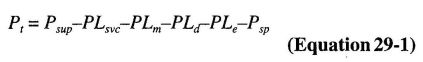
where:
Pt = Pressure used in applying Tables R313.3.6.2(4) through R313.3.6.2(9).
Psup = Pressure available from the water supply source.
PLsvc = Pressure loss in the water-service pipe.
PLm = Pressure loss in the water meter.
PLd = Pressure loss from devices other than the water meter.
PLe = Pressure loss associated with changes in elevation.
PLsp = Maximum pressure required by a sprinkler.
R313.3.6.2.2 Calculation procedure. Determination of the required size for water distribution piping shall be in accordance with the following procedure:
Step 1-Determine Psup
Obtain the static supply pressure that will be available from the water main from the water purveyor, or for an individual source, the available supply pressure shall be in accordance with Section R313.3.5.1.
Step 2-Determine PLsvc
Use Table R313.3.6.2(1) to determine the pressure loss in the water service pipe based on the selected size of the water service.
Step 3-Determine PLm
Use Table R313.3.6.2(2) to determine the pressure loss from the water meter, based on the selected water meter size.
Step 4-Determine PLd
Determine the pressure loss from devices other than the water meter installed in the piping system supplying sprinklers, such as pressure-reducing valves, backflow preventers, water softeners or water filters. Device pressure losses shall be based on the device manufacturer’s specifications. The flow rate used to determine pressure loss shall be the rate from Section R313.3.4.2, except that 5 gpm (0.3 L/S) shall be added where the device is installed in a water-service pipe that supplies more than one dwelling. As alternative to deducting pressure loss for a device, an automatic bypass valve shall be installed to divert flow around the device when a sprinkler activates.
Step 5 - DeterminePLe
Use Table R313.3.6.2(3) to determine the pressure loss associated with changes in elevation. The elevation used in applying the table shall be the difference between the elevation where the water source pressure was measured and the elevation of the highest sprinkler.
Step 6 - DeterminePsp
Determine the maximum pressure required by any individual sprinkler based on the flow rate from Section R313.3.4.1. The required pressure is provided in the sprinkler manufacturer’s published data for the specific sprinkler model based on the selected flow rate.
Step 7 - CalculatePt
Using Equation 29-1, calculate the pressure available to offset friction loss in water-distribution piping between the service valve and the sprinklers.
Step 8 - Determine the maximum allowable pipe length
Use Tables R313.3.6.2(4) through R313.3.6.2(9) to select a material and size for water distribution piping. The piping material and size shall be acceptable if the developed length of pipe between the service valve and the most remote sprinkler does not exceed the maximum allowable length specified by the applicable table. Interpolation of Pt between the tabular values shall be permitted.
The maximum allowable length of piping in Tables R313.3.6.2(4) through R313.3.6.2(9) incorporates an adjustment for pipe fittings, and no additional consideration of friction losses associated with pipe fittings shall be required.
R313.3.7 Instructions and signs. An owner’s manual for the fire sprinkler system shall be provided to the owner. A sign or valve tag shall be installed at the main shutoff valve to the water distribution system stating the following: “Warning, the water system for this home supplies fire sprinklers that require certain flows and pressures to fight a fire. Devices that restrict the flow or decrease the pressure or automatically shut off the water to the fire sprinkler system, such as water softeners, filtration systems and automatic shutoff valves, shall not be added to this system without a review of the fire sprinkler system by a fire protection specialist. Do not remove this sign.”
R313.3.8 Inspections. The water distribution system shall be inspected in accordance with Sections R313.3.8.1 and R313.3.8.2.
R313.3.8.1 Preconcealment inspection. The following items shall be verified prior to the concealment of any sprinkler system piping:
R313.3.8.2 Final inspection. The following items shall be verified upon completion of the system:
| FLOW RATE (gallons per minute, gpm)b | 5/8 INCH METER PRESSURE LOSS (pounds per square inch, psi) | ¾ INCH METER PRESSURE LESS (pounds per square inch, psi) | 1 INCH METER PRESSURE LOSS (pounds per square inch, psi) |
|---|---|---|---|
| For SI: 1 inch = 25.4 mm, 1 pound per square inch = 6.895 kPa, 1 gallon per minute = 0.063 L/s. | |||
| NP - Not permitted unless the actual water meter pressure loss is known. | |||
| a. Table R313.3.6.2(2) establishes conservative values for water meter pressure loss or installations where the water meter loss is unknown. Where the actual water meter pressure loss is known, Pnv shall be the actual loss. | |||
| b. Flow rate from Section R313.3.4.2. Add 5 gpm to the flow rate required by Section R313.3.4.2 where the water-service pipe supplies more than one dwelling. | |||
| 8 | 2 | 1 | 1 |
| 10 | 3 | 1 | 1 |
| 12 | 4 | 1 | 1 |
| 14 | 5 | 2 | 1 |
| 16 | 7 | 3 | 1 |
| 18 | 9 | 4 | 1 |
| 20 | 11 | 4 | 2 |
| 22 | NP | 5 | 2 |
| 24 | NP | 5 | 2 |
| 26 | NP | 6 | 2 |
| 28 | NP | 6 | 2 |
| 30 | NP | 7 | 2 |
| 32 | NP | 7 | 3 |
| 34 | NP | 8 | 3 |
| 36 | NP | 8 | 3 |
| ELEVATION (feet) | PRESSURE LOSS (psi) |
|---|---|
| For SI: 1 foot = 304.8 mm, 1 pound per square inch = 6.895 kPa. | |
| 5 | 2.2 |
| 10 | 4.4 |
| 15 | 6.5 |
| 20 | 8.7 |
| 25 | 10.9 |
| 30 | 13 |
| ult35 | 15.2 |
| 40 | 17.4 |
| SPRINKLER FLOW RATEa (gpm) | WATER DISTRIBUTION SIZE (inch) | AVAILABLE PRESSURE - Pt (psi) | |||||||||
|---|---|---|---|---|---|---|---|---|---|---|---|
| 15 | 20 | 25 | 30 | 35 | 40 | 45 | 50 | 55 | 60 | ||
| Allowable length of pipe from service valve to farthest sprinkler (feet) | |||||||||||
| For SI: 1 inch = 25.4 mm, 1 foot = 304.8 mm, 1 pound per square inch = 6.895 kPa. 1 gallon per minute = 0.963 L/s. | |||||||||||
| NP - Not permitted | |||||||||||
| a. Flow rate from Section R313.3.4.2. | |||||||||||
| 8 | ¾ | 217 | 289 | 361 | 434 | 506 | 578 | 650 | 723 | 795 | 867 |
| 9 | ¾ | 174 | 232 | 291 | 349 | 407 | 465 | 523 | 581 | 639 | 697 |
| 10 | ¾ | 143 | 191 | 239 | 287 | 335 | 383 | 430 | 478 | 526 | 574 |
| 11 | ¾ | 120 | 160 | 200 | 241 | 281 | 321 | 361 | 401 | 441 | 481 |
| 12 | ¾ | 102 | 137 | 171 | 205 | 239 | 273 | 307 | 341 | 375 | 410 |
| 13 | ¾ | 88 | 118 | 147 | 177 | 206 | 235 | 265 | 294 | 324 | 353 |
| 14 | ¾ | 77 | 103 | 128 | 154 | 180 | 205 | 231 | 257 | 282 | 308 |
| 15 | ¾ | 68 | 90 | 113 | 136 | 158 | 181 | 203 | 226 | 248 | 271 |
| 16 | ¾ | 60 | 80 | 100 | 120 | 140 | 160 | 180 | 200 | 220 | 241 |
| 17 | ¾ | 54 | 72 | 90 | 108 | 125 | 143 | 161 | 179 | 197 | 215 |
| 18 | ¾ | 48 | 64 | 81 | 97 | 113 | 129 | 145 | 161 | 177 | 193 |
| 19 | ¾ | 44 | 58 | 73 | 88 | 102 | 117 | 131 | 146 | 160 | 175 |
| 20 | ¾ | 40 | 53 | 66 | 80 | 93 | 106 | 119 | 133 | 146 | 159 |
| 21 | ¾ | 36 | 48 | 61 | 73 | 85 | 97 | 109 | 121 | 133 | 145 |
| 22 | ¾ | 33 | 44 | 56 | 67 | 78 | 89 | 100 | 111 | 122 | 133 |
| 23 | ¾ | 31 | 41 | 51 | 61 | 72 | 82 | 92 | 102 | 113 | 123 |
| 24 | ¾ | 28 | 38 | 47 | 57 | 66 | 76 | 85 | 95 | 104 | 114 |
| 25 | ¾ | 26 | 35 | 44 | 53 | 61 | 70 | 79 | 88 | 97 | 105 |
| 26 | ¾ | 24 | 33 | 41 | 49 | 57 | 65 | 73 | 82 | 90 | 98 |
| 27 | ¾ | 23 | 30 | 38 | 46 | 53 | 61 | 69 | 76 | 84 | 91 |
| 28 | ¾ | 21 | 28 | 36 | 43 | 50 | 57 | 64 | 71 | 78 | 85 |
| 29 | ¾ | 20 | 27 | 33 | 40 | 47 | 53 | 60 | 67 | 73 | 80 |
| 30 | ¾ | 19 | 25 | 31 | 38 | 44 | 50 | 56 | 63 | 69 | 75 |
| 31 | ¾ | 18 | 24 | 29 | 35 | 41 | 47 | 53 | 59 | 65 | 71 |
| 32 | ¾ | 17 | 22 | 28 | 33 | 39 | 44 | 50 | 56 | 61 | 67 |
| 33 | ¾ | 16 | 21 | 26 | 32 | 37 | 42 | 47 | 53 | 58 | 63 |
| 34 | ¾ | NP | 20 | 25 | 30 | 35 | 40 | 45 | 50 | 55 | 60 |
| 35 | ¾ | NP | 19 | 24 | 28 | 33 | 38 | 42 | 47 | 52 | 57 |
| 36 | ¾ | NP | 18 | 22 | 27 | 31 | 36 | 40 | 45 | 49 | 54 |
| 37 | ¾ | NP | 17 | 21 | 26 | 30 | 34 | 38 | 43 | 47 | 51 |
| 38 | ¾ | NP | 16 | 20 | 24 | 28 | 32 | 36 | 40 | 45 | 49 |
| 39 | ¾ | NP | 15 | 19 | 23 | 27 | 31 | 35 | 39 | 42 | 46 |
| 40 | ¾ | NP | NP | 18 | 22 | 26 | 29 | 33 | 37 | 40 | 44 |
| SPRINKLER FLOW RATEa (gpm) | WATER DISTRIBUTION SIZE (inch) | AVAILABLE PRESSURE - Pt (psi) | |||||||||
|---|---|---|---|---|---|---|---|---|---|---|---|
| 15 | 20 | 25 | 30 | 35 | 40 | 45 | 50 | 55 | 60 | ||
| Allowable length of pipe from service valve to farthest sprinkler (feet) | |||||||||||
| For SI: 1 inch = 25.4 mm, 1 foot = 304.8 mm, 1 pound per square inch = 6.895 kPa, 1 gallon per minute = 0.963 L/s. | |||||||||||
| a. Flow rate from Section R313.3.4.2. | |||||||||||
| 8 | 1 | 806 | 1075 | 1343 | 1612 | 1881 | 2149 | 2418 | 2687 | 2955 | 3224 |
| 9 | 1 | 648 | 864 | 1080 | 1296 | 1512 | 1728 | 1945 | 2161 | 2377 | 2593 |
| 10 | 1 | 533 | 711 | 889 | 1067 | 1245 | 1422 | 1600 | 1778 | 1956 | 2134 |
| 11 | 1 | 447 | 586 | 745 | 894 | 1043 | 1192 | 1341 | 1491 | 1640 | 1789 |
| 12 | 1 | 381 | 508 | 634 | 761 | 888 | 1015 | 1142 | 1269 | 1396 | 1523 |
| 13 | 1 | 328 | 438 | 547 | 657 | 766 | 875 | 985 | 1094 | 1204 | 1313 |
| 14 | 1 | 286 | 382 | 477 | 572 | 668 | 763 | 859 | 954 | 1049 | 1145 |
| 15 | 1 | 252 | 336 | 420 | 504 | 588 | 672 | 756 | 840 | 924 | 1008 |
| 16 | 1 | 224 | 298 | 373 | 447 | 522 | 596 | 671 | 745 | 820 | 894 |
| 17 | 1 | 200 | 266 | 333 | 400 | 466 | 533 | 600 | 666 | 733 | 799 |
| 18 | 1 | 180 | 240 | 300 | 360 | 420 | 479 | 539 | 599 | 659 | 719 |
| 19 | 1 | 163 | 217 | 271 | 325 | 380 | 434 | 488 | 542 | 597 | 651 |
| 20 | 1 | 148 | 197 | 247 | 296 | 345 | 395 | 444 | 493 | 543 | 592 |
| 21 | 1 | 135 | 180 | 225 | 270 | 315 | 360 | 406 | 451 | 496 | 541 |
| 22 | 1 | 124 | 165 | 207 | 248 | 289 | 331 | 372 | 413 | 455 | 496 |
| 23 | 1 | 114 | 152 | 190 | 228 | 267 | 305 | 343 | 381 | 419 | 457 |
| 24 | 1 | 106 | 141 | 176 | 211 | 246 | 282 | 317 | 352 | 387 | 422 |
| 25 | 1 | 98 | 131 | 163 | 196 | 228 | 261 | 294 | 326 | 359 | 392 |
| 26 | 1 | 91 | 121 | 152 | 182 | 212 | 243 | 273 | 304 | 334 | 364 |
| 27 | 1 | 85 | 113 | 142 | 170 | 198 | 226 | 255 | 283 | 311 | 340 |
| 28 | 1 | 79 | 106 | 132 | 159 | 185 | 212 | 238 | 265 | 291 | 318 |
| 29 | 1 | 74 | 99 | 124 | 149 | 174 | 198 | 223 | 248 | 273 | 298 |
| 30 | 1 | 70 | 93 | 116 | 140 | 163 | 186 | 210 | 233 | 256 | 280 |
| 31 | 1 | 66 | 88 | 110 | 132 | 153 | 175 | 197 | 219 | 241 | 263 |
| 32 | 1 | 62 | 83 | 103 | 124 | 145 | 165 | 186 | 207 | 227 | 248 |
| 33 | 1 | 59 | 78 | 98 | 117 | 137 | 156 | 176 | 195 | 215 | 234 |
| 34 | 1 | 55 | 74 | 92 | 111 | 129 | 148 | 166 | 185 | 203 | 222 |
| 35 | 1 | 53 | 70 | 88 | 105 | 123 | 140 | 158 | 175 | 193 | 210 |
| 36 | 1 | 50 | 66 | 83 | 100 | 116 | 133 | 150 | 166 | 183 | 199 |
| 37 | 1 | 47 | 63 | 79 | 95 | 111 | 126 | 142 | 158 | 174 | 190 |
| 38 | 1 | 45 | 60 | 75 | 90 | 105 | 120 | 135 | 150 | 165 | 181 |
| 39 | 1 | 43 | 57 | 72 | 86 | 100 | 115 | 129 | 143 | 158 | 172 |
| 40 | 1 | 41 | 55 | 68 | 82 | 96 | 109 | 123 | 137 | 150 | 164 |
| SPRINKLER FLOW RATEa (gpm) | WATER DISTRIBUTION SIZE (inch) | AVAILABLE PRESSURE - Pt (psi) | |||||||||
|---|---|---|---|---|---|---|---|---|---|---|---|
| 15 | 20 | 25 | 30 | 35 | 40 | 45 | 50 | 55 | 60 | ||
| Allowable length of pipe from service valve to farthest sprinkler (feet) | |||||||||||
| For SI: 1 inch = 25.4 mm, 1 foot = 304.8 mm, 1 pound per square inch = 6.895 kPa, 1 gallon per minute = 0.963 L/s. | |||||||||||
| Flow rate from Section R313.3.4.2. | |||||||||||
| 8 | ¾ | 348 | 465 | 581 | 697 | 813 | 929 | 1045 | 1161 | 1278 | 1394 |
| 9 | ¾ | 280 | 374 | 467 | 560 | 654 | 747 | 841 | 934 | 1027 | 1121 |
| 10 | ¾ | 231 | 307 | 384 | 461 | 538 | 615 | 692 | 769 | 845 | 922 |
| 11 | ¾ | 193 | 258 | 322 | 387 | 451 | 515 | 580 | 644 | 709 | 773 |
| 12 | ¾ | 165 | 219 | 274 | 329 | 384 | 439 | 494 | 549 | 603 | 658 |
| 13 | ¾ | 142 | 189 | 237 | 284 | 331 | 378 | 426 | 473 | 520 | 568 |
| 14 | ¾ | 124 | 165 | 206 | 247 | 289 | 330 | 371 | 412 | 454 | 495 |
| 15 | ¾ | 109 | 145 | 182 | 218 | 254 | 290 | 327 | 363 | 399 | 436 |
| 16 | ¾ | 97 | 129 | 161 | 193 | 226 | 258 | 290 | 322 | 354 | 387 |
| 17 | ¾ | 86 | 115 | 144 | 173 | 202 | 230 | 259 | 288 | 317 | 346 |
| 18 | ¾ | 78 | 104 | 130 | 155 | 181 | 207 | 233 | 259 | 285 | 311 |
| 19 | ¾ | 70 | 94 | 117 | 141 | 164 | 188 | 211 | 234 | 258 | 281 |
| 20 | ¾ | 64 | 85 | 107 | 128 | 149 | 171 | 192 | 213 | 235 | 256 |
| 21 | ¾ | 58 | 78 | 97 | 117 | 136 | 156 | 175 | 195 | 214 | 234 |
| 22 | ¾ | 54 | 71 | 89 | 107 | 125 | 143 | 161 | 179 | 197 | 214 |
| 23 | ¾ | 49 | 66 | 82 | 99 | 115 | 132 | 148 | 165 | 181 | 198 |
| 24 | ¾ | 46 | 61 | 76 | 91 | 107 | 122 | 137 | 152 | 167 | 183 |
| 25 | ¾ | 42 | 56 | 71 | 85 | 99 | 113 | 127 | 141 | 155 | 169 |
| 26 | ¾ | 39 | 52 | 66 | 79 | 92 | 105 | 118 | 131 | 144 | 157 |
| 27 | ¾ | 37 | 49 | 61 | 73 | 86 | 98 | 110 | 122 | 135 | 147 |
| 28 | ¾ | 34 | 46 | 57 | 69 | 80 | 92 | 103 | 114 | 126 | 137 |
| 29 | ¾ | 32 | 43 | 54 | 64 | 75 | 86 | 96 | 107 | 118 | 129 |
| 30 | ¾ | 30 | 40 | 50 | 60 | 70 | 81 | 91 | 101 | 111 | 121 |
| 31 | ¾ | 28 | 38 | 47 | 57 | 66 | 76 | 85 | 95 | 104 | 114 |
| 32 | ¾ | 27 | 36 | 45 | 54 | 63 | 71 | 80 | 89 | 98 | 107 |
| 33 | ¾ | 25 | 34 | 42 | 51 | 59 | 68 | 76 | 84 | 93 | 101 |
| 34 | ¾ | 24 | 32 | 40 | 48 | 56 | 64 | 72 | 80 | 88 | 96 |
| 35 | ¾ | 23 | 30 | 38 | 45 | 53 | 61 | 68 | 76 | 83 | 91 |
| 36 | ¾ | 22 | 29 | 36 | 43 | 50 | 57 | 65 | 72 | 79 | 86 |
| 37 | ¾ | 20 | 27 | 34 | 41 | 48 | 55 | 61 | 68 | 75 | 82 |
| 38 | ¾ | 20 | 26 | 33 | 39 | 46 | 52 | 59 | 65 | 72 | 78 |
| 39 | ¾ | 19 | 25 | 31 | 37 | 43 | 50 | 56 | 62 | 68 | 74 |
| 40 | ¾ | 18 | 24 | 30 | 35 | 41 | 47 | 53 | 59 | 65 | 71 |
| SPRINKLER FLOW RATEa (gpm) | WATER DISTRIBUTION SIZE (inch) | AVAILABLE PRESSURE - Pt(psi) | |||||||||
|---|---|---|---|---|---|---|---|---|---|---|---|
| 15 | 20 | 25 | 30 | 35 | 40 | 45 | 50 | 55 | 60 | ||
| Allowable length of pipe from service valve to farthest sprinkler (feet) | |||||||||||
| For SI: 1 inch = 25.4 mm, 1 foot = 304.8 mm, 1 pound per square inch = 6.895 kPa, 1 gallon per minute = 0.963 L/s. | |||||||||||
| a. Flow rate from Section R313.3.4.2. | |||||||||||
| 8 | 1 | 1049 | 1398 | 1748 | 2098 | 2447 | 2797 | 3146 | 3496 | 3845 | 4195 |
| 9 | 1 | 843 | 1125 | 1406 | 1687 | 1968 | 2249 | 2530 | 2811 | 3093 | 3374 |
| 10 | 1 | 694 | 925 | 1157 | 1388 | 1619 | 1851 | 2082 | 2314 | 2545 | 2776 |
| 11 | 1 | 582 | 776 | 970 | 1164 | 1358 | 1552 | 1746 | 1940 | 2133 | 2327 |
| 12 | 1 | 495 | 660 | 826 | 991 | 1156 | 1321 | 1486 | 1651 | 1816 | 1981 |
| 13 | 1 | 427 | 570 | 712 | 854 | 997 | 1139 | 1281 | 1424 | 1566 | 1709 |
| 14 | 1 | 372 | 497 | 621 | 745 | 869 | 993 | 1117 | 1241 | 1366 | 1490 |
| 15 | 1 | 328 | 437 | 546 | 656 | 765 | 874 | 983 | 1093 | 1202 | 1311 |
| 16 | 1 | 291 | 388 | 485 | 582 | 679 | 776 | 873 | 970 | 1067 | 1164 |
| 17 | 1 | 260 | 347 | 433 | 520 | 607 | 693 | 780 | 867 | 954 | 1040 |
| 18 | 1 | 234 | 312 | 390 | 468 | 546 | 624 | 702 | 780 | 858 | 936 |
| 19 | 1 | 212 | 282 | 353 | 423 | 494 | 565 | 635 | 706 | 776 | 847 |
| 20 | 1 | 193 | 257 | 321 | 385 | 449 | 513 | 578 | 642 | 706 | 770 |
| 21 | 1 | 176 | 235 | 293 | 352 | 410 | 469 | 528 | 586 | 645 | 704 |
| 22 | 1 | 161 | 215 | 269 | 323 | 377 | 430 | 484 | 538 | 592 | 646 |
| 23 | 1 | 149 | 198 | 248 | 297 | 347 | 396 | 446 | 496 | 545 | 595 |
| 24 | 1 | 137 | 183 | 229 | 275 | 321 | 366 | 412 | 458 | 504 | 550 |
| 25 | 1 | 127 | 170 | 212 | 255 | 297 | 340 | 382 | 425 | 467 | 510 |
| 26 | 1 | 118 | 158 | 197 | 237 | 276 | 316 | 355 | 395 | 434 | 474 |
| 27 | 1 | 111 | 147 | 184 | 221 | 258 | 295 | 332 | 368 | 405 | 442 |
| 28 | 1 | 103 | 138 | 172 | 207 | 241 | 275 | 310 | 344 | 379 | 413 |
| 29 | 1 | 97 | 129 | 161 | 194 | 226 | 258 | 290 | 323 | 355 | 387 |
| 30 | 1 | 91 | 121 | 152 | 182 | 212 | 242 | 273 | 303 | 333 | 364 |
| 31 | 1 | 86 | 114 | 143 | 171 | 200 | 228 | 257 | 285 | 314 | 342 |
| 32 | 1 | 81 | 108 | 134 | 161 | 188 | 215 | 242 | 269 | 296 | 323 |
| 33 | 1 | 76 | 102 | 127 | 152 | 178 | 203 | 229 | 254 | 280 | 305 |
| 34 | 1 | 72 | 96 | 120 | 144 | 168 | 192 | 216 | 240 | 265 | 289 |
| 35 | 1 | 68 | 91 | 114 | 137 | 160 | 182 | 205 | 228 | 251 | 273 |
| 36 | 1 | 65 | 87 | 108 | 130 | 151 | 173 | 195 | 216 | 226 | 260 |
| 37 | 1 | 62 | 82 | 103 | 123 | 144 | 165 | 185 | 206 | 226 | 247 |
| 38 | 1 | 59 | 78 | 98 | 117 | 137 | 157 | 176 | 196 | 215 | 235 |
| 39 | 1 | 56 | 75 | 93 | 112 | 131 | 149 | 168 | 187 | 205 | 224 |
| 40 | 1 | 53 | 71 | 89 | 107 | 125 | 142 | 160 | 178 | 196 | 214 |
| SPRINKLER FLOW RATEa (gpm) | WATER DISTRIBUTION SIZE (inch) | AVAILABLE PRESSURE - Pt(psi) | |||||||||
|---|---|---|---|---|---|---|---|---|---|---|---|
| 15 | 20 | 25 | 30 | 35 | 40 | 45 | 50 | 55 | 60 | ||
| Allowable length of pipe from service valve to farthest sprinkler (feet) | |||||||||||
| For SI: 1 inch = 25.4 mm, 1 foot = 304.8 mm, 1 pound per square inch = 6.895 kPa, 1 gallon per minute = 0.963 L/s. | |||||||||||
| NP - Not permitted. | |||||||||||
| a. Flow rate from Section R313.3.4.2. | |||||||||||
| 8 | ¾ | 93 | 123 | 154 | 185 | 216 | 247 | 278 | 309 | 339 | 370 |
| 9 | ¾ | 74 | 99 | 124 | 149 | 174 | 199 | 223 | 248 | 273 | 298 |
| 10 | ¾ | 61 | 82 | 102 | 123 | 143 | 163 | 184 | 204 | 225 | 245 |
| 11 | ¾ | 51 | 68 | 86 | 103 | 120 | 137 | 154 | 171 | 188 | 205 |
| 12 | ¾ | 44 | 58 | 73 | 87 | 102 | 117 | 131 | 146 | 160 | 175 |
| 13 | ¾ | 38 | 50 | 63 | 75 | 88 | 101 | 113 | 126 | 138 | 151 |
| 14 | ¾ | 33 | 44 | 55 | 66 | 77 | 88 | 99 | 110 | 121 | 132 |
| 15 | ¾ | 29 | 39 | 48 | 58 | 68 | 77 | 87 | 96 | 106 | 116 |
| 16 | ¾ | 26 | 34 | 43 | 51 | 60 | 68 | 77 | 86 | 94 | 103 |
| 17 | ¾ | 23 | 31 | 38 | 46 | 54 | 61 | 69 | 77 | 84 | 92 |
| 18 | ¾ | 21 | 28 | 34 | 41 | 48 | 55 | 62 | 69 | 76 | 83 |
| 19 | ¾ | 19 | 25 | 31 | 37 | 44 | 50 | 56 | 62 | 69 | 75 |
| 20 | ¾ | 17 | 23 | 28 | 34 | 40 | 45 | 51 | 57 | 62 | 68 |
| 21 | ¾ | 16 | 21 | 26 | 31 | 36 | 41 | 47 | 52 | 57 | 62 |
| 22 | ¾ | NP | 19 | 24 | 28 | 33 | 38 | 43 | 47 | 52 | 57 |
| 23 | ¾ | NP | 17 | 22 | 26 | 31 | 35 | 39 | 44 | 48 | 52 |
| 24 | ¾ | NP | 16 | 20 | 24 | 28 | 32 | 36 | 40 | 44 | 49 |
| 25 | ¾ | NP | NP | 19 | 22 | 26 | 30 | 34 | 37 | 41 | 45 |
| 26 | ¾ | NP | NP | 17 | 21 | 24 | 28 | 31 | 35 | 38 | 42 |
| 27 | ¾ | NP | NP | 16 | 20 | 23 | 26 | 29 | 33 | 36 | 39 |
| 28 | ¾ | NP | NP | 15 | 18 | 21 | 24 | 27 | 30 | 33 | 36 |
| 29 | ¾ | NP | NP | NP | 17 | 20 | 23 | 26 | 28 | 31 | 34 |
| 30 | ¾ | NP | NP | NP | 16 | 19 | 21 | 24 | 27 | 29 | 32 |
| 31 | ¾ | NP | NP | NP | 15 | 18 | 20 | 23 | 25 | 28 | 30 |
| 32 | ¾ | NP | NP | NP | NP | 17 | 19 | 21 | 24 | 26 | 28 |
| 33 | ¾ | NP | NP | NP | NP | 16 | 18 | 20 | 22 | 25 | 27 |
| 34 | ¾ | NP | NP | NP | NP | NP | 17 | 19 | 21 | 23 | 25 |
| 35 | ¾ | NP | NP | NP | NP | NP | 16 | 18 | 20 | 22 | 24 |
| 36 | ¾ | NP | NP | NP | NP | NP | 15 | 17 | 19 | 21 | 23 |
| 37 | ¾ | NP | NP | NP | NP | NP | NP | 16 | 18 | 20 | 22 |
| 38 | ¾ | NP | NP | NP | NP | NP | NP | 16 | 17 | 19 | 21 |
| 39 | ¾ | NP | NP | NP | NP | NP | NP | NP | 16 | 18 | 20 |
| 40 | ¾ | NP | NP | NP | NP | NP | NP | NP | 16 | 17 | 19 |
| SPRINKLER FLOW RATEa (gpm) | WATER DISTRIBUTION SIZE (inch) | AVAILABLE PRESSURE - Pt(psi) | |||||||||
|---|---|---|---|---|---|---|---|---|---|---|---|
| 15 | 20 | 25 | 30 | 35 | 40 | 45 | 50 | 55 | 60 | ||
| Allowable length of pipe from service valve to farthest sprinkler (feet) | |||||||||||
| For SI: 1 inch = 25.4 mm, 1 foot = 304.8 mm, 1 pound per square inch = 6.895kPa, 1 gallon per minute = 0.963 L/s. | |||||||||||
| Flow rate from Section R313.3.4.2. | |||||||||||
| 8 | 1 | 314 | 418 | 523 | 628 | 732 | 837 | 941 | 1046 | 1151 | 1255 |
| 9 | 1 | 252 | 336 | 421 | 505 | 589 | 673 | 757 | 841 | 925 | 1009 |
| 10 | 1 | 208 | 277 | 346 | 415 | 485 | 554 | 623 | 692 | 761 | 831 |
| 11 | 1 | 174 | 232 | 290 | 348 | 406 | 464 | 522 | 580 | 638 | 696 |
| 12 | 1 | 148 | 198 | 247 | 296 | 346 | 395 | 445 | 494 | 543 | 593 |
| 13 | 1 | 128 | 170 | 213 | 256 | 298 | 341 | 383 | 426 | 469 | 511 |
| 14 | 1 | 111 | 149 | 186 | 223 | 260 | 297 | 334 | 371 | 409 | 446 |
| 15 | 1 | 98 | 131 | 163 | 196 | 229 | 262 | 294 | 327 | 360 | 392 |
| 16 | 1 | 87 | 116 | 145 | 174 | 203 | 232 | 261 | 290 | 319 | 348 |
| 17 | 1 | 78 | 104 | 130 | 156 | 182 | 208 | 233 | 259 | 285 | 311 |
| 18 | 1 | 70 | 93 | 117 | 140 | 163 | 187 | 210 | 233 | 257 | 280 |
| 19 | 1 | 63 | 84 | 106 | 127 | 148 | 169 | 190 | 211 | 232 | 253 |
| 20 | 1 | 58 | 77 | 96 | 115 | 134 | 154 | 173 | 192 | 211 | 230 |
| 21 | 1 | 53 | 70 | 88 | 105 | 123 | 140 | 158 | 175 | 193 | 211 |
| 22 | 1 | 48 | 64 | 80 | 97 | 113 | 129 | 145 | 161 | 177 | 193 |
| 23 | 1 | 44 | 59 | 74 | 89 | 104 | 119 | 133 | 148 | 163 | 178 |
| 24 | 1 | 41 | 55 | 69 | 82 | 96 | 110 | 123 | 137 | 151 | 164 |
| 25 | 1 | 38 | 51 | 64 | 76 | 89 | 102 | 114 | 127 | 140 | 152 |
| 26 | 1 | 35 | 47 | 59 | 71 | 83 | 95 | 106 | 118 | 130 | 142 |
| 27 | 1 | 33 | 44 | 55 | 66 | 77 | 88 | 99 | 110 | 121 | 132 |
| 28 | 1 | 31 | 41 | 52 | 62 | 72 | 82 | 93 | 103 | 113 | 124 |
| 29 | 1 | 29 | 39 | 48 | 58 | 68 | 77 | 87 | 97 | 106 | 116 |
| 30 | 1 | 27 | 36 | 45 | 54 | 63 | 73 | 82 | 91 | 100 | 109 |
| 31 | 1 | 26 | 34 | 43 | 51 | 60 | 68 | 77 | 85 | 94 | 102 |
| 32 | 1 | 24 | 32 | 40 | 48 | 56 | 64 | 72 | 80 | 89 | 97 |
| 33 | 1 | 23 | 30 | 38 | 46 | 53 | 61 | 68 | 76 | 84 | 91 |
| 34 | 1 | 22 | 29 | 36 | 43 | 50 | 58 | 65 | 72 | 79 | 86 |
| 35 | 1 | 20 | 27 | 34 | 41 | 48 | 55 | 61 | 68 | 75 | 82 |
| 36 | 1 | 19 | 26 | 32 | 39 | 45 | 52 | 58 | 65 | 71 | 78 |
| 37 | 1 | 18 | 25 | 31 | 37 | 43 | 49 | 55 | 62 | 68 | 74 |
| 38 | 1 | 18 | 23 | 29 | 35 | 41 | 47 | 53 | 59 | 64 | 70 |
| 39 | 1 | 17 | 22 | 28 | 33 | 39 | 45 | 50 | 56 | 61 | 67 |
| 40 | 1 | 16 | 21 | 27 | 32 | 37 | 43 | 48 | 53 | 59 | 64 |
R314.1 Smoke detection and notification. All smoke alarms shall be listed in accordance with UL 217 and installed in accordance with the provisions of this code and the household fire warning equipment provisions of NFPA 72. Systems and components shall be California State Fire Marshal listed and approved in accordance with California Code of Regulations, Title 19, Division 1 for the purpose for which they are installed.
R314.2 Smoke detection systems. Household fire alarm systems installed in accordance with NFPA 72 that include smoke alarm's, or a combination of smoke detector and audible notification device installed as required by this section for smoke alarms, shall be permitted. The household fire alarm system shall provide the same level of smoke detection and alarm as required by this section for smoke alarms. Where a household fire warning system is installed using a combination of smoke detector and audible notification device(s), it shall become a permanent fixture of the occupancy and owned by the homeowner. The system shall be monitored by an approved supervising station and be maintained in accordance with NFPA 72.
Exception: Where smoke alarms are provided meeting the requirements of Section R314.4.
R314.3 Location. Smoke alarms shall be installed in the following locations:
When more than one smoke alarm is required to be installed within an individual dwelling unit the alarm devices shall be interconnected in such a manner that the actuation of one alarm will activate all of the alarms in the individual unit.
R314.3.1 Alterations, repairs and additions. When alterations,repairs or additions requiring a permit occur, or when one or more sleeping rooms are added or created in existing dwellings, the individual dwelling unit shall be equipped with smoke alarms located as required for new dwellings.
Exceptions: See Section R314.6.
R314.4 Power source. Smoke alarms shall receive their primary power from the building wiring provided that such wiring is served from a commercial source and shall be equipped with a battery backup. Smoke alarms with integral strobes that are not equipped with battery backup shall be connected to an emergency electrical system. Smoke alarms shall emit a signal when the batteries are low. Wiring shall be permanent and without a disconnecting switch other than as required for overcurrent protection.
Exceptions:
- Smoke alarms are permitted to be solely battery operated in existing buildings where no construction is taking place.
- Smoke alarms are permitted to be solely battery operated in buildings that are not served from a commercial power source.
- Smoke alarms are permitted to be solely battery operated in existing areas of buildings undergoing alterations or repairs that do not result in the removal of interior walls or ceiling finishes exposing the structure, unless there is an attic, crawl space or basement available which could provide access for building wiring without the removal of interior finishes.
R314.5 Interconnection. Where more than one smoke alarm is required to be installed within an individual dwelling or sleeping unit, the smoke alarms shall be interconnected in such a manner that the activation of one alarm will activate all of the alarms in the individual unit. The alarm shall be clearly audible in all bedrooms over background noise levels with all intervening doors closed.
Exceptions:
- Interconnection is not required in buildings that are not undergoing alterations, repairs or construction of any kind.
- Smoke alarms in existing areas are not required to be interconnected where alterations or repairs do not result in the removal of interior wall or ceiling finishes exposing the structure, unless there is an attic, crawl space or basement available which could provide access for interconnection without the removal of interior finishes.
R314.6 Existing Group R-3 occupancies.
R314.6.1 Existing buildings housing Group R-3 occupancies established prior to the effective date of these regulations may have their use continued if they conform or are made to conform to provisions of these regulations to the extent that reasonable and adequate life safety against the hazards of fire, panic and explosion is substantially provided. Additional means of egress, the installation of automatic sprinkler systems, automatic fire alarm system or other life safety measures may be required to provide reasonable and adequate safety.
Note: It is the intent of this section that every existing occupancy need not mandatorily conform with the requirements for new construction. Reasonable judgement in the application of requirements must be exercised by the enforcing agency.
R314.6.2 For purposes of clarification, Health and Safety Code Section 13113.7 is repeated.
However, if any local rule, regulation, or ordinance, adopted prior to the compliance dates specified in paragraphs (1) and (2) requires installation in a dwelling unit intended for human occupancy of smoke detector, which receive their power from the electrical system of the building and requires compliance with the local rule, regulation, or ordinance at a date subsequent to the dates specified in this section, the compliance date specified in the rule, regulation, or ordinance shall, but only with respect to the dwelling units specified in this section, take precedence over the dates specified in this section.
The State Fire Marshal may adopt regulations exempting dwellings intended for human occupancy with fire sprinkler systems from the provisions of this section, if he or she determines that a smoke detector is not reasonably necessary for fire safety in the occupancy.
Unless prohibited by local rules, regulations, or ordinances, a battery-operated smoke detector which otherwise meets the standards adopted pursuant to Section 13114 for smoke detectors, satisfies the requirements of this section.
An owner or the owner’s agent may enter any dwelling unit, efficiency dwelling unit, guest room, and suite owner by the owner for the purpose of installing, repairing, testing, and maintaining single station smoke detectors required by this section. Except in cases of emergency, the owner or owner’s agent shall give the tenants of each such unit, room, or suite reasonable notice in writing of the intention to enter and shall enter only during normal business hours. Twenty-four hours shall be presumed to be reasonable notice in absence of evidence to the contrary.
The smoke detector shall be operable at the time that the tenant takes possession. The apartment complex tenant shall be responsible for notifying the manager or owner if the tenant becomes aware of an inoperable smoke detector within his or her unit. The owner or authorized agent shall correct any reported deficiencies in the smoke detector and shall not be in violation of this section for a deficient smoke detector when he or she has not received notice of the deficiency.
R314.6.3 For purposes of clarification,Health and Safety Code Section 13113.8 is repeated.
R315.1 Carbon monoxide alarms. For new construction, an approved carbon monoxide alarm shall be installed in dwelling
96units and in sleeping units within which fuel- burning appliances are installed and in dwelling units that have attached garages.
R315.1.1 Power supply. For new construction required carbon monoxide alarms shall receive their primary power from the building wiring where such wiring is served from a commercial source and shall be equipped with a battery back-up. Alarm wiring shall be directly connected to the permanent building wiring without a disconnecting switch other than as required for overcurrent protection.
Exceptions:
- In dwelling units where there is no commercial power supply the carbon monoxide alarm may be solely battery operated.
- In existing dwelling units a carbon monoxide alarm is permitted to be solely battery operated where repairs or alterations do not result in the removed of wall and ceiling finishes or there is no access by means of attic, basement or crawl space.
R315.1.2 Interconnection. Where more than one carbon monoxide alarm is required to be installed within the dwelling unit or within a sleeping unit the alarm shall be interconnected in a manner that activation of one alarm shall activate all of the alarms in the individual unit.
Exception:
- Interconnection is not required in existing dwelling units where repairs do not result in the removal of wall and ceiling finishes, there is no access by means of attic, basement or crawl space, and no previous method for interconnection existed.
R315.2 Where required in existing dwellings. Where a permit is required for alterations, repairs or additions exceeding one thousand dollars ($1,000), existing dwellings or sleeping units that have attached garages or fuel- burning appliances shall be provided with a carbon monoxide alarm in accordance with Section R315.1. Carbon monoxide alarm shall only be required in the specific dwelling unit or sleeping unit for which the permit was obtained.
R315.3 Alarm requirements. Single and multiple-station carbon monoxide alarm shall be listed as complying with the requirements of UL 2034. Carbon monoxide detectors shall be listed as complying with the requirements of UL 2075. Carbon monoxide alarms and carbon monoxide detectors shall be installed in accordance with this code, the current edition of NFPA 720 “Standard for the Installation of Carbon Monoxide (CO) Detection and Warning Equipment” and the manufacturer's installation instructions. Other carbon monoxide alarm and detection devices as recognized in NFPA 720 are also acceptable.
Carbon monoxide alarms required by Sections R315.1 and R315.2 shall be installed in the following locations:
R315.3.1 Multiple-purpose alarms. Carbon monoxide alarms combined with smoke alarms shall comply with Section R315, all applicable standards, and requirements for listing and approval by the Office of the State Fire Marshall, for smoke alarms.
R316.1 General. The provisions of this section shall govern the materials, design, application, construction and installation of foam plastic materials.
R316.2 Labeling and identification. Packages and containers of foam plastic insulation and foam plastic insulation components delivered to the job site shall bear the label of an approved agency showing the manufacturer's name, the product listing, product identification and information sufficient to determine that the use will comply with the requirements.
R316.3 Surface burning characteristics. Unless otherwise allowed in Section R316.5 or R316.6, all foam plastic or foam plastic cores used as a component in manufactured assemblies used in building construction shall have a flame spread index of not more than 75 and shall have a smoke-developed index of not more than 450 when tested in the maximum thickness intended for use in accordance with ASTM E 84 or UL 723. Loose-fill type foam plastic insulation shall be tested as board stock for the flame spread index and smoke-developed index.
Exception: Foam plastic insulation more than 4 inches (102 mm) thick shall have a maximum flame spread index of 75 and a smoke-developed index of 450 where tested at a minimum thickness of 4 inches (102 mm), provided the end use is approved in accordance with Section R316.6 using the thickness and density intended for use.
R316.4 Thermal barrier. Unless otherwise allowed in Section R316.5 or Section R316.6, foam plastic shall be separated from the interior of a building by an approved thermal barrier of minimum ½ inch (12.7 mm) gypsum wallboard or an approved finish material equivalent to a thermal barrier material that will limit the average temperature rise of the unexposed surface to no more than 250°F (139°C) after 15 minutes of fire exposure complying with ASTM E 119 or UL 263 standard time temperature curve. The thermal barrier shall be installed in such a manner that it will remain in place for 15 minutes based on NFPA 286 with the acceptance criteria of Section R 302.9.4, FM 4880, UL 1040 or UL 1715.
R316.5 Specific requirements. The following requirements shall apply to these uses of foam plastic unless specifically approved in accordance with Section R316.6 or by other sections of the code or the requirements of Sections R316.2 through R316.4 have been met.
R316.5.1 Masonry or concrete construction. The thermal barrier specified in Section R316.4 is not required in a masonry or concrete wall, floor or roof when the foam plastic insulation is separated from the interior of the building by a minimum 1-inch (25 mm) thickness of masonry or concrete.
97R316.5.2 Roofing. The thermal barrier specified in Section R316.4 is not required when the foam plastic in a roof assembly or under a roof covering is installed in accordance with the code and the manufacturer′;s installation instructions and is separated from the interior of the building by tongue-and-groove wood planks or wood structural panel sheathing in accordance with Section R803, not less than 15/32 inch (11.9 mm) thick bonded with exterior glue and identified as Exposure 1, with edges supported by blocking or tongue-and-groove joints or an equivalent material. The smoke-developed index for roof applications shall not be limited.
R316.5.3 Attics. The thermal barrier specified in Section R316.4 is not required where all of the following apply:
The above ignition barrier is not required where the foam plastic insulation has been tested in accordance with Section R316.6.
R316.5.4 Crawl spaces. The thermal barrier specified in Section R316.4 is not required where all of the following apply:
The above ignition barrier is not required where the foam plastic insulation has been tested in accordance with Section R316.6.
R316.5.5 Foam-filled exterior doors. Foam-filled exterior doors are exempt from the requirements of Sections R316.3 and R316.4.
R316.5.6 Foam-filled garage doors. Foam-filled garage doors in attached or detached garages are exempt from the requirements of Sections R316.3 and R316.4.
R316.5.7 Foam backer board. The thermal barrier specified in Section R316.4 is not required where siding backer board foam plastic insulation has a maximum thickness of 0.5 inch (12.7 mm) and a potential heat of not more than 2000 Btu per square foot (22 720 kJ/m2) when tested in accordance with NFPA 259 provided that:
R316.5.8 Re-siding. The thermal barrier specified in Section R316.4 is not required where the foam plastic insulation is installed over existing exterior wall finish in conjunction with re-siding provided the foam plastic has a maximum thickness of 0.5 inch (12.7 mm) and a potential heat of not more than 2000 Btu per square foot (22 720 kJ/m2) when tested in accordance with NFPA 259.
R316.5.9 Interior trim. The thermal barrier specified in Section R316.4 is not required for exposed foam plastic interior trim, provided all of the following are met:
R316.5.10 Interior finish. Foam plastics shall be permitted as interior finish where approved in accordance with Section R316.6 Foam plastics that are used as interior finish shall also meet the flame spread index and smoke-developed index requirements of Section R302.9.1 and R302.9.2.
R316.5.11 Sill plates and headers. Foam plastic shall be permitted to be spray applied to a sill plate and header with out the thermal barrier specified in Section R316.4 subject to all of the following:
R316.5.12 Sheathing. Foam plastic insulation used as sheathing shall comply with Section R316.3 and Section R316.4. Where the foam plastic sheathing is exposed to the attic space at a gable or kneewall, the provisions of Section R316.5.3 shall apply.
R316.6 Specific approval. Foam plastic not meeting the requirements of Section R316.3 through R316.5 shall be specifically approved on the basis of one of the following approvedtests: NFPA 286 with the acceptance criteria of Section R302.9.4, FM 4880, UL 723, UL 1040 or UL 1715, or fire tests related to actual end-use configurations. The specific approval shall be based on the actual end use configuration and shall be performed on the finished foam plastic assembly in the maximum thickness intended for use. Assemblies tested shall include seams, joints and other typical details used in the installation of the assembly and shall be tested in the manner intended for use.
R316.7 Termite damage. The use of foam plastics in areas of “very heavy” termite infestation probability shall be in accordance with Section R318.4.
R317.1 Location required. Protection of wood and wood based products from decay shall be provided in the following locations by the use of naturally durable wood or wood that is preservation-treated in accordance with AWPA U1 for the species, product, preservative and end use. Preservatives shall be listed in Section 4 of AWPA U1.
R317.1.1 Field treatment. Field-cut ends, notches and drilled holes of preservative-treated wood shall be treated in the field in accordance with AWPA M4.
R317.1.2 Ground contact. All wood in contact with the ground, embedded in concrete in direct contact with the ground or embedded in concrete exposed to the weather that supports permanent structures intended for human occupancy shall be approved pressure-preservative-treated wood suitable for ground contact use, except intreated wood may be used where entirely below groundwater level or continuously submerged in fresh water.
R317.1.3 Geographical areas. In geographical areas where experience has demonstrated a specific need, approved naturally durable or pressure-preservative-treated wood shall be used for those portions of wood members that form the structural supports of buildings, balconies, porches or similar permanent building appurtenances when those members are exposed to the weather without adequate protection from a roof, eave, overhand or other covering that would prevent moisture or water accumulation on the surface or at joints between members. Depending on local experience, such members may include:
R317.1.4 Wood columns. Wood columns shall be approved wood of natural decay resistance or approved pressure-preservative-treated wood.
Exceptions:
- Columns exposed to the weather or in basements when supported by concrete piers of metal pedestals projecting 1 inch (25.4 mm) above a concrete floor or 6 inches (152 mm) above exposed earth and the earth is covered by an approved impervious moisture barrier.
- Columns in enclosed crawl spaces or unexcavated areas located within the periphery of the building when supported by a concrete pier or metal pedestal at a height more than 8 inches (203 mm) from exposed earth and the earth is covered by an impervious moisture barrier.
R317.1.5 Exposed glued-laminated timbers. The portions of glued-laminated timbers that form the structural supports of a building or other structure and are exposed to weather and not properly protected by a roof, eave or similar covering shall be pressure treated with preservative, or be
99manufactured from naturally durable or preservative-treated wood.
R317.2 Quality mark. Lumber and plywood required to the pressure-preservative-treated in accordance with Section R318.1 shall bear the quality mark of an approved inspection agency that maintains continuing supervision, testing and inspection over the quality of the product and that has been approved by an accreditation body that complies with the requirements of the American Lumber Standard Committee treated wood program.
R317.2.1 Required information. The required quality mark on each piece of pressure-preservative-treated lumber or plywood shall contain the following information:
Exception: Quality markson lumber less than 1 inch (25.4 mm) nominal thickness, or lumber less than nominal 1 inch by 5 inches (25.4 mm by 127 mm) or 2 inches by 4 inches (51 mm by 102 mm) or lumber 36 inches (914 mm) or less in length shall be applied by stamping the faces of exterior pieces or by end labeling not less than 25 percent of the pieces of a bundled unit.
R317.3 Fasteners and connectors in contact with preservative-treated and fire-retardant-treated wood. Fasteners and connectors in contact with preservative-treated wood and fire-retardant-treated wood shall be in accordance with this section. The coating weights for zinc-coated fasteners shall be in accordance with ASTM A 153.
R317.3.1 Fasteners for preservative-treated wood. Fasteners for preservative-treated wood shall be of hot dipped zinc-coated galvanized steel, stainless steel, silicon bronze or copper. Coating types and weights for connectors in contact with preservative-treated wood shall be in accordance with the connector manufacturer’s recommandations. In the absence of manufacturer’s recommendations, a minimum of ASTM A 653 type G 185 zinc-coated galvanized steel, or equivalent, shall be used.
Exceptions:
R317.3.2 Fastenings for wood foundations. Fastenings for wood foundations shall be as required in AF&PA Technical Report No. 7.
R317.3.3 Fasteners for fire-retardant-treated wood used in exterior applications or wet or damp locations. Fasteners for fire-retardant-treated wood used in exterior applications or wet or damp locations shall be of hot-dipped zinc-coated galvanized steel, stainless steel, silicon bronze or copper. Fasteners other than nails and timber rivers shall be permitted to be of mechanically deposited zinc-coated steel with coating weights in accordance with ASTM B 695, Class 55 minimum.
R317.3.4 Fasteners for fire-retardant-treated wood used in interior applications. Fasteners for fire-retardant-treated wood used in interior locations shall be in accordance with the manufacturer′; recommendations. In the absence of the manufacturer′; recommendations, Section R317.3.3 shall apply.
R317.4 Wood/plastic composites. Wood/plastic composites used in exterior deck boards, stair treads, handrails and guard-rail systems shall bear a label indicating the required performance levels and demonstrating compliance with the provisions of ASTM D 7032.
R317.4.1 Wood/plastic composites shall be installed in accordance with the manufacturer’s instruction.
R318.1 Subterranean termite control methods. In areas subject to damage from termites as indicated by Table R301.2(1), methods of protection shall be one of the following methods or a combination of these methods:
R318.1.1 Quality mark. Lumber and plywood required to be pressure-preservative-treated in accordance with Section R318.1 shall bear the quality mark of an approved inspection agency which maintains continuing supervision, testing and inspection over the quality of the product and which has been approved by an accreditation body which complies with the requirements of the American Lumber Standard Committee treated wood program.
R318.1.2 Field treatment. Field-cut ends, notches, and drilled holes of pressure-preservative-treated wood shall be retreated in the field in accordance with AWPA M4.
R318.2 Chemical termiticide treatment. Chemical termiticide treatment shall include soil treatment and/or field applied wood treatment. The concentration, rate of application
100and method of treatment of the chemical termiticide shall be in strict accordance with the termiticide label.
R318.3 Barriers. Approved Physical barriers, such as metal or plastic sheeting or collars specifically designed for termite prevention, shall be installed in a manner to prevent termites from entering the structure. Shields placed on top of an exterior foundation wall are permitted to be used only if in combination with another method of protection.
R318.4 Foam plastic protection. In areas where the probability of termite infestation is “very heavy” as indicated in Figure R301.2(6), extruded and expanded polystyrene, polyisocyanurate and other foam plastics shall not be installed on the exterior face or under interior or exterior foundation walls or slab foundations located below grade. The clearance between foam plastics installed above grade. and exposed earth shall be at least 6 inches (152 mm).
Exceptions:
- Buildings where the structural members of walls, floors, ceilings and roofs are entirely of noncombustible materials or pressure-preservative-treated wood.
- When in addition to the requirements of Section R318.1, an approved method of protecting the foam plastic and structure from subterranean termite damage is used.
- On the interior side of basement walls.
R319.1 Address numbers. Buildings shall have approved address numbers, building numbers or approved building identification placed in a position that is plainly legible and visible from the street or road fronting the property. These numbers shall contrast with their background. Address numbers shall be Arabic numbers or alphabetical letters. Numbers shall be a minimum of 4 inches (102 mm) high with a minimum stroke width of ½inch (12.7 mm). Where access is by means of a private road and the building address cannot be viewed from the public way, a monument, pole or other sign or means shall be used to identify the structure.
R320.1 Scope. Dwelling units in a building consisting of three or more dwelling units or four or more condominium units shall meet the requirements of the California Building Code Chapter 11A. Covered Multifamily Dwellings include but are not limited to dwelling units listed in Section 1.8.1.1.2. Dwelling units within a single structure separated by firewalls do not constitute separate buildings.
R321.1 Elevators. Where provided, passenger elevators, limited-use/limited-application elevators or private residence elevators shall comply with ASME A17.1.
R321.2 Platform lifts. Where provided, platform lifts shall comply with ASME A18.1.
R321.3 Accessibility. Elevators or platform (wheelchair) lifts that are part of an accessible route required by Chapter 11A of the California Building Code, shall comply with ASME A 17.1, Safety Code for Elevators and Escalators, Title 8, of the California Code of Regulations, under “Elevator Safety Orders”; ASME A 18.1, Safety Standard for Platform Lifts and Stairway Chair Lifts; the State of California, the Department of Industrial Relations, Division of Occupational Safety and Health, and any applicable safety regulations of other administrative authorities having jurisdiction. See Section 1124A of the California Building Code for additional information.
R322.1 General. Buildings and structures constructed in whole or in part in flood hazard areas (including A or V Zones) as established in Table R301.2(1)shall be designed and constructed in accordance with the provisions contained in this section.
Exception: Buildings and structures located in whole or in part in identified floodways shall be designed and constructed in accordance with ASCE 24.
R322.1.1 Alternative provisions. As an alternative to the requirements in Section R322.3 for buildings and structures located in whole or in part in coastal high-hazard areas (V Zones), ASCE 24 is permitted subject to the limitations of this code and the limitations therein.
R322.1.2 Structural systems. All structural systems of all buildings and structures shall be designed, connected and anchored to resist flotation, collapse or permanent lateral movement due to structural loads and stresses from flooding equal to the design flood elevation.
R322.1.3 Flood-resistant construction. All buildings and structures erected in areas prone to flooding shall be constructed by methods and practices that minimize flood damage.
R322.1.4 Establishing the design flood elevation. The design flood elevation shall be used to define areas prone to flooding. At a minimum, the design flood elevation is the higher of:
R322.1.4.1 Determination of design flood elevations. If design flood elevations are not specified, the building official is authorized to require the applicant to:
R322.1.4.2 Determination of impacts. In riverine flood hazard areas where design flood elevations are specified but floodways have not been designated, the applicant shall demonstrate that the effect of the proposed buildings and structures on design flood elevations, including fill, when combined with all other existing and anticipated flood hazard area encroachments, will not increase the design flood elevation more than 1 foot (305 mm) at any point within the jurisdiction.
R322.1.5 Lowest floor. The lowest floor shall be the floor of the lowest enclosed area, including basement, but excluding any unfinished flood-resistant enclosure that is useable solely for vehicle parking, building access or limited storage provided that such enclosure is not built so as to render the building or structure in violation of this section.
R322.1.6 Protection of mechanical and electrical systems. Electrical systems, equipment and components; heating, ventilating, air conditioning; plumbing appliances and plumbing fixtures; duct systems; and other service equipment shall be located at or above the elevation required in Section R322.2 (flood hazard areas including A Zones) or R322.3 (coastal high-hazard areas including V Zones). If replaced as part of a substantial improvement, electrical systems, equipment and components; heating, ventilating, air conditioning and plumbing appliances and plumbing fixtures; duct systems; and other service equipment shall meet the requirements of this section. Systems, fixtures, and equipment and components shall not be mounted on or penetrate through walls intended to break away under flood loads.
Exception: Locating electrical systems, equipment and components; heating, ventilating, air conditioning; plumbing appliances and plumbing fixtures; duct systems; and other serviceequipment is permitted below the elevation required in Section R322.2 (flood hazard areas Including A Zones) or R322.3 (coastal high-hazard areas Including V Zones) provided that they are designed and installed to prevent water from entering or accumulating within the components and to resist hydrostatic and hydrodynamic loads and stresses, including the effects of buoyancy, during the occurrence, of flooding to the design flood elevation in accordance with ASCE 24. Electrical wiring systems are permitted to be located below the required elevation provided they conform to the provisions of the California Electrical Code for wet locations.
R322.1.7 Protection of water supply and sanitary sewage systems. Water supply shall be designed to minimize or eliminate infiltration of flood waters into the water supply and distribution system. Sanitary sewage systems shall be designed to minimize or eliminate infiltration of floodwaters into sanitary drainage systems and discharges from sanitary drainage systems into floodwaters.
R322.1.8 Flood-resistant materials. Building materials used below the elevation required in Section R322.2 (flood hazard areas including A Zones) or R322.3 (coastal high-hazard areas including V Zones) shall comply with the following:
R322.1.10 As-built elevation documentation. A registered design professional shall prepare and seal documentation of the elevations specified in Section R322.2 or R322.3.
R322.2 Flood hazard areas (including A Zones). All areas that have been determined to be prone to flooding but not subject to high velocity wave action shall be designated as flood hazard areas. Flood hazard areas that have been delineated as subject to wave heights between 1½ feet (457 mm) and 3 feet (914 mm) shall be designated as Coastal A Zones. All building and structures constructed in whole or in part in flood hazard areas shall be designed and constructed in accordance with Sections R322.2.1 through R322.2.3.
R322.2.1 Elevation requirements.
Exception: Enclosed areas below the design flood elevation, including basements whose floors are not below
102grade on all sides, shall meet the requirements of Section R322.2.2.
R322.2.2 Enclosed area below design flood elevation. Enclosed areas, including crawl spaces, that are below the design flood elevation shall:
R322.2.3 Foundation design and construction. Foundation walls for all buildings and structures erected in flood hazard areas shall meet the requirements of Chapter 4.
Exception: Unless designed in accordance with Section R404:
- The unsupported height of 6-inch (152 mm) plain masonry walls shall be no more than 3 feet (914 mm).
- The unsupported height of 8-inch (203 mm) plain masonry walls shall be no more than 4 feet (1219 mm).
- The unsupported height of 8-inch (203 mm) reinforced masonry walls shall be no more than 8 feet (2438 mm).
For the purpose of this exception, unsupported height is the distance from the finished grade of the under-floor space and the top of the wall.
R322.3 Coastal high-hazard areas (including V Zones).
Areas that have been determined to be subject to wave heights in excess of 3 feet (914 mm) or subject to high-velocity wave action or wave-induced crosion shall be designated as coastal high-hazard areas. Buildings and structures constructed in whole or in part in coastal high-hazard areas shall be designed and constructed in accordance with Sections R322.3.1 through R322.3.6.
R322.3.1 Location and site preparation.
R322.3.2 Elevation requirements.
Exception: Walls and partitions enclosing areas below the design flood elevation shall meet the requirements of Sections R322.3.4 and R322.3.5.
R322.3.3 Foundations. Buildings and structures erected in coastal high-hazard areas shall be supported on pilings or columns and shall be adequately anchored to those pilings or columns. Pilings shall have adequate soil penetrations to resist the combined wave and wind loads (lateral and uplift). Water loading values used shall be those associated with the design flood. Wind loading values shall be those required by
103this code. Pile embedment shall include consideration of decreased resistance capacity caused by scour of soil strata surrounding the piling. Pile systems design and installation shall be certified in accordance with Section R322.3.6. Mat, raft or other foundations that support columns shall not be permitted where soil investigations that are required in accordance with Section R401.4 indicate that soil material under the mat, raft or other foundation is subject to scour or erosion from wave-velocity flow conditions. Slabs, pools, pool decks and walkways shall be located and constructed to be structurally independent of buildings and structures and their foundations to prevent transfer of flood loads to the buildings and structures during conditions of flooding, scour or erosion from wave-velocity flow conditions, unless the buildings and structures and their foundation are designed to resist the additional flood load.
R322.3.4 Walls below design flood elevation. Walls and partitions are permitted below the elevated floor, provided that such walls and partitions are not part of the structural support of the building or structure and:
R322.3.5 Enclosed areas below design flood elevation.Enclosed areas below the design flood elevation shall be used solely for parking of vehicles, building access or storage.
R322.3.6 Construction documents. The construction documents shall include documentation that is prepared and sealed by a registered design professional that the design and methods of construction to be used meet the applicable criteria of this section.
R323.1 General. This section applies to the construction of storm shelters when constructed as separate detached buildings or when constructed as safe rooms within buildings for the purpose of providing safe rooms within buildings for the purpose of providing safe refuge from storms that produce high winds, such as tornados and hurricanes. In addition to other applicable requirements in this code, storm shelters shall be constructed in accordance with ICC/NSSA-500.
R325.1 Scope. The provisions of this section shall apply to 24-hour care facilities in a Group R-3.1 occupancy licensed by a governmental agency.
R325.2 General. The provisions in this section shall apply in addition to general requirements in this code.
R325.2.1 Restrainst shall not be practiced in a Group R-3.1 occupancy.
Exception: Occupancies which meet all the requirements for a Group I-3 occupancy.
R325.2.2 Pursuant to Health and Safety Code Section 13133, regulations of the state fire marshal pertaining to Occupancies classified as Residential Facilities (RF) and Residential-Care Facilities for the Elderly (RCFE) shall apply uniformly throughout the state and no city, county, city and county, including a charter city or charter county, or fire protection district shall adopt or enforce any ordinance or local rule or regulation relating to fire and panic safety which is inconsistent with these regulations. A city, county, city and county, including a charter city or charter county may pursuant to Health and Safety Code Section 13143.5, or a fire protection district may pursuant to Health and Safety Code Section 13869.7, adopt standards more stringent than those adopted by the state fire marshal that are reasonably necessary to accommodate local climate, geological, or topographical conditions relating to roof coverings for Residential-Care Facilities for the Elderly.
Exception: Local regulations relating to roof coverings in facilities licensed as a Residential Care Facility for the Elderly (RCFE) per Health and Safety Code Section 13133.
R325.3 Building height and area provisions.
R325.3.1 Limitations six or less clients. Group R-3.1 occupancies where clients are housed above the first story, having more than two stories in height or having more than 3,000 square feet (279 m2) of floor area above the first story
104shall not be of less than one-hour fire-resistance-rated construction throughout.
In Group R-3.1 occupanices housing a bedridden client, the client sleeping room shall not be located above or below the first story.
Exception:Clients who become bedridden as a result of a temporary illness as defined in Health and Safety Code Sections 1566.45, 1568.0832 and 1569.72. A temporary illness is an illness which persists for 14 days or less. A bedridden client may be retained in excess of the 14 days upon approval by the Department of Social Services and may continue to be housed on any story in a Group R-3.1 occupancy classified as a licensed residential facility.
Every licensee admitting or retaining a bedridden resident shall, within 48 hours of the resident’s admission or retention in the facility, notify the local fire authority with jurisdiction of the estimated length of time the resident will retain his or her bedridden status in the facility.
R325.3.2. Buildings housing protective social- care homes or in occupancies housing inmates who are not restrained need not be of one-hour fire-resistive construction when not more than two stories in height. In no case shall individual floor areas exceed 3,000 square feet (279m2). The fire-resistive protection of the exterior walls shall not be less than one hour where such walls are located within 5 feet (1524 mm) of the property line. Openings within such walls are not permitted. Openings in exterior non-rated walls need not be protected.
R325.4 Interior finish provisions.
R325.4.1 Interior wall and ceiling finish. Group R-3.1 occupancies housing a bedridden client shall comply with Interior Wall and Ceilding Finish requirements specified for Group I-2 occupancies in Table 803.5 of the California Building code.
R325.5 Fire protection system provisions.
R325.5.1 Automatic sprinkler systems in Group R-3.1 occupancies. An automatic sprinkler system shall be installed where required in Section 313.
Exceptions:
- Existing Group R-3.1 occupancies coverted to Group R-3.1 occupancies not housing bedridden clients, not housing nonambulatory clients above the first floor, and not housing clients above the second floor.
- Existing Group R-3 occupancies converted to Group R-3.1 occupancies housing only one bedridden client and complying with Section R325.6.3.3.
- Pursuant to Health and Safety Code Section 13113 existing occupancies housing ambulatory children only, none of whom are mentally ill or mentally retarded, and the buildings or portions thereof in which such children are housed are not more than two stories in height, and buildings or portions thereof housing such children have an automatic fire alarm system activated by approved smoke detectors.
- Pursuant to Health and Safety Code Section 13143.6 existing occupancies licensed for protective social care which house ambulatory clients only, none of whom is a child (under the age of 18 years), or who is elderly (65 years of age or over).
R325.5.2 Smoke alarms in Group R-3.1 occupancies.Smoke alarms shall be installed where required in Section 314. In addition to the provisions set forth in Section R314 the following shall apply:
R325.5.2.1 Audible alarm signal. The audible signal shall be the standard fire alarm evacuation signal, ANSI S3.41 Audible Emergency Evacuation Signal, “three pulse temporal pattern,” as described in NFPA 72.
R325.5.2.2 Hearing impaired. See Section 907.9.1 of the California Building Code.
R325.5.2.3 Visible alarms. Visible alarm notification appliances shall be provided in accordance with Sections 907.5.2.3.1 through 907.5.2.3.5 of the California Building Codes.
Exceptions:
- Visible alarm notification appliances are not required in alterations, except where an existing fire alarm system is upgraded or replaced, or a new fire alarm system in installed.
- Visible alarm notification appliances shall not be required in enclosed exit stairways, exterior exit stairs and exterior exit ramps.
- Visible alarm notification appliances shall not be required in elevator cars.
R325.5.2.4 Protective social care facilities in Group R-3.1. Protective social care facilities which house persons who are hearing impaired shall be provided with notification appliances for the hearing impaired.
105installed in accordance with NFPA 72 and which shall activated upon initiation of the fire alarm system or the smoke alarms.
Exception: The use of the existing evacuation signaling scheme shall be permitted where approved by the enforcing agency.
R325.6 Means of egress provisions.
R325.6.1 General. In addition to the general means of egress requirements of Chapter 10 of the California Building Code, this section shall apply to Group R-3.1 occupancies.
R325.6.2 Number of exits.
R325.6.2.1 Group R-3.1 occupancies shall have a minimum of two exits.
R325.6.3 Egress arrangements.
R325.6.3.1 Egress through adjoining dwelling units shall not be permitted.
R325.6.3.2 Group R-3.1 occupancies housing nonambulatory clients. In a Group R-3.1 occupancy, bedrooms used by nonambulatory clients shall have access to at least one of the required exits which shall conform to one of the following:
R325.6.3.3 Group R-3.1 occupancies housing only one bedridden client. In Group R-3.1 occupancies housing a bedridden client and not provided with an approved automatic fire sprinkler system, all of the following shall apply:
Note: A sliding glass door can be used as an exterior exit doorway as long as it is operable from the inside and outside and the clear width of the exit way is not less than 32 inches (813 mm).
R325.6.3.4 Intervening rooms. A means of exit shall not pass through more than one intervening room. A means of egress shall not pass through kitchens, storerooms, closets, garages or spaces used for similar purposes.
Exception: Kitchens which do not form separate rooms by construction.
R325.6.4 Changes in level. In Group R-3.1 occupancies housing nonambulatory clients interior changes in level up to 0.25 inch (6 mm) may be vertical and without edge treatment. Changes in level between 0.25 inch (6 mm) and 0.5 inch (12.7 mm) shall be beveled with a slope no greater than 1 unit vertical in 2 units horizontal (50% slope). Changes in level greater than 0.5 inch (12.7 mm) shall be accomplished by means of a ramp.
R325.6.5 Stairways. Group R-3.1 occupancies may continue to use existing stairways (except for winding and spiral stairways which are not permitted as a required means of egress) provided the stairs have a maximum rise of 8 inches
106(203 mm) with a minimum run of 9 inches (229 mm). The minimum stairway width may be 30 inches (762 mm).
R325.6.6 Floor separation. Group R-3.1 occupancies shall be provided with a nonfire resistance constructed floor separation at stairs which will prevent smoke migration between floors. Such floor separation shall have equivalent construction of 0.5 inch (12.7 mm) gypsum wallboard on one side of wall framing.
Exceptions:
- Occupancies with at least one exterior exit from floors occupied by clients.
- Occupancies provided with automatic fire sprinkler systems complying with Chapter 9.
R325.6.6.1 Doors within floor separations. Doors within such floor separations shall be tight fitting solid wood at least 1 3/8 inches (35 mm) in thickness. Door glazing shall not exceed 1296 square inches (32 918 mm2) with no dimension greater than 54 inches (1372 mm). Such doors shall be positive latching, smoke gasketed and shall be automatic-closing by smoke detection.
R325.6.7 Fences and gates. Grounds of a Residential Care for the Elderly facility serving Alzheimer clients may be fenced and gates therein equipped with locks, provided safe dispersal areas are located not less than 50 feet (15 240 mm) from the buildings. Dispersal areas shall be sized to provide an area of not less than 3 square feet (0.28 m2) per occupant. Gates shall not be installed across corridors or passageways leading to such dispersal areas unless they comply with egress requirements.
R325.6.8 Basement exits. One exit is required to grade level when the basement is accessible to clients.
R325.6.9 Delayed egress locks. See Section 1008.1.8.6 of the California Building Code.
R325.7 Request for alternate means of protection for facilities housing bedridden clients. Request for alternate means of protection shall apply to Sections R325 through R325.7. Request for approval to use an alternative material, assembly or materials, equipment, method of construction, method of installation of equipment or means of protection shall be made in writing to the local fire authority having jurisdiction by the facility, client or the client’s authorized representative. Sufficient evidence shall be submitted to substantiate the need for an alternate means of protection.
The facility, client or the client’s representative or the local fire authority having jurisdiction may request a written opinion from the State Fire Marshal concerning the interpretation of the regulations promulgated by the State Fire Marshal for a particular factual dispute. The State Fire Marshal shall issue the written opinion within 45 days following the request.
Approval of a request for use of an alternative material, assembly or materials, equipment, method of construction, method of installation of equipment or means of protection made pursuant to this section shall be limited to Group R-3.1 occupancies housing a bedridden client.
Approvals made by the local fire authority having jurisdiction and the written opinion by the State Fire Marshal shall be applicable only to the requesting facility and shall not be construed as establishing any precedent for any future request by that facility or any other facility.
R325.8 Temporarily bedridden clients. Clients who become temporarily bedridden as defined in Health and Safety Code Section 1569.72, as enforced by the Department of Social Services, may continue to be housed on any story in Group R-3.1 occupancies classified as Residential Care Facilities for the Elderly (RCFE). Every Residential Care Facility for the Elderly (RCFE) admitting or retaining a bedridden resident shall, within 48 hours of the resident’s admission or retention in the facility, notify the local fire authority with jurisdiction of the estimated length of time the resident will retain his or her bedridden status in the facility.
R326.1 Large family day-care homes.
R326.2 For purposes of clarification, Health and Safety Code Section 1597.46 is repeated.
Any noise standards shall be consistent with local noise ordinances implementing the noise element of the general plan and shall take into consideration the noise levels generated by children.
The local government shall process any required permit as economically as possible, and fees charged for review shall not exceed the costs of the review and permit process. Not less than 10 days prior to the date on which the decision will be made on the application, the zoning administrator or person designated to handle such use permits shall give notice of the proposed use by mail or delivery to all owners shown on the last equalized assessment roll as owning real property within a 100 foot radius of the exterior boundaries of the proposed large family day care home. No hearing on the application for a permit issued pursuant to this paragraph shall be held before a decision is made unless a hearing is requested by the applicant or other affected person. The applicant or other affected person may appeal the decision. The appellant shall pay the cost, if any of the appeal.
R326.3 Smoke alarms. Large family day-care homes shall be equipped with State Fire Marshal approved and listed single station residential type smoke alarms. The number and placement of smoke alarms shall be determined by the enforcement authority.
R326.4 Fire extinguishers. Large and small family day-care homes shall be equipped with a portable fire extinguisher having a minimum 2A10BC rating.
R326.5 Fire alarm devices. Every large family day-care home shall be provided with at least one manual device at a location approved by the authority having jurisdiction. Such device shall actuate a fire alarm signal, which shall be audible throughout the facility at a minimum level of 15 db above ambient noise level. These devices need not be interconnected to any other fire alarm device, have a control panel or be electrically supervised or provided with emergency power. Such device or devices shall be attached to the structure and may be of any type acceptable to the enforcing agent, provided that such devices are distinctive in tone and are audible throughout the structure.
R326.6 Compliance. Every large-family day-care home shall comply with the provisions for Group R-3 occupancies and, if appropriate, Section 326.1. For the purposes of Section 326.1, the first story shall be designated as the floor used for residential occupancy nearest to the street level which provides primary access to the building.
Enforcement of the provisions shall be in accordance with the Health and Safety Code Sections 13145 and 13146. No city, county, city and county, or district shall adopt or enforce any building ordinance or local rule or regulation relating to the subject of fire and life safety in large-family day-care homes which is inconsistent with those standards adopted by the State Fire Marshal, except to the extent the building ordinance or local rule or regulation applies to single-family residences in which day care is not provided.
R326.7 Special hazards. Every unenclosed gas-fired water heater or furnace which is within the area used for child care in a large family day-care home shall be protected in such a way as to prevent children from making contact with those appliances.
Exception: This does not apply to kitchen stoves or ovens.
R326.8 Exiting. Every story or basement of a large family day-care home shall be provided with two exits which are remotely located from each other. Every required exit shall be of a size to permit the installation of a door not less than 32 inches (813 mm) in clear width and not less than 6 feet 8 inches (2032 mm) in height. A manually operated horizontal sliding door may be used as one of the two required exits.
Where basements are used for day-care purposes, one of the two required exits shall provide access directly to the exterior without entering the first story. The second exit from the basement may either pass through the story above or exit directly to the exterior.
Rooms used for day-care purposes shall not be located above the first story.
Exception: Buildings equipped with an automatic sprinkler system throughout and which have at least one of the required exits providing access directly to the exterior. NFPA 13R may be used in large family day-care homes. The sprinkler omissions of NFPA 13R shall not apply unless approved by the enforcing agency.
Exit doors, including manually operated horizontal sliding doors, shall be openable from the inside without use of a key or any special knowledge or effort.
R327.1.1 Scope. This chapter applies to building materials, systems and or assemblies used in the exterior design and construction of new buildings located within a Wildland-Urban Interface Fire Area as defined in Section R327.2.
R327.1.2 Purpose. The purpose of this Chapter is to establish minimum standards for the protection of life and prop-
108erty by increasing the ability of a building located in any Fire Hazard Severity Zone within State Responsibility Areas or any Wildland-Urban Interface Fire Area to resist the intrusion of flame or burning embers projected by a vegetation fire and contributes to a systematic reduction in conflagration losses.
R327.1.3. Application. New buildings located in any Fire Hazard Severity Zone or any Wildland-Urban Interface Fire Area designated by the enforcing agency constructed after the application date shall comply with the provisions of this chapter.
Exceptions:
- Buildings of an accessory character classified as a Group U occupancy and not exceeding 120 square feet in floor area, when located at least 30 feet from an applicable building.
- Buildings of an accessory character classified as Group U occupancy of any size located least 50 feet from an applicable building.
- Buildings classified as a Group U Agricultural Building, as defined in Section 202 of this code (see also Appendix C - Group U Agricultural Buildings), when located at least 50 feet from an applicable building.
- Additions to and remodels of buildings originally constructed prior to the applicable application date.
R327.1.3.1 Application date and where required. New buildings for which an application for a building permit is submitted on or after July 1, 2008 located in any Fire Hazard Severity Zone or Wildland Interface Fire Area shall comply with all sections of this chapter, including all of the following areas:
Exceptions:
- New buildings located in any Fire Hazard Severity Zone within State Responsibility Areas, for which an application for a building permit is submitted on or after January 1, 2008, shall comply with all sections of this chapter.
- New buildings located in any Fire Hazard Severity Zone within State Responsibility Areas or any Wildland Interface Fire Area designated by cities and other local agencies for which an application for a building permit is submitted on or after December 1, 2005 but prior to July 1, 2008 shall only comply with the following sections of this chapter:
- Section R327.5– Roofing
- Section R327.6–Vents
R327.1.4 Inspection and certification. Building permit applications and final completion approvals for buildings within the scope and application of this chapter shall comply with the following:
R327.1.5 Vegetation management compliance. Prior to building permit final approval, the property shall be in compliance with the vegetation management requirements prescribed in California Fire Code section 4906, including California Public Resources Code 4291 or California Government Code Section 51182. Acceptable methods of compliance inspection and documentation shall be determined by the enforcing agency and may include any of the following:
For the purposes of this chapter, certain terms are defined below:
CDF DIRECTOR means the Director of the California Department of Forestry and Fire Protection.
EXTERIOR COVERING. The exposed siding or cladding material applied to the exterior side of an exterior wall, roof eave soffit, floor projection or exposed underfloor framing.
FIRE PROTECTION PLAN is a document prepared for a specific project or development proposed for a Wildland-Urban Interface Fire Area. It describes ways to minimize and mitigate potential for loss from wildfire exposure. The Fire Protection Plan shall be in accordance with this chapter and the California Fire Code, Chapter 49. When required by the enforcing agency for the purposes of granting modifications, a fire protection plan shall be submitted. Only locally adopted ordinances that have been filed with the California Building Standards Commission or the Department of Housing and Community Development in accordance with Section 1.1.8 shall apply.
FIRE HAZARD SEVERITY ZONES are geographical areas designated pursuant to California Public Resources Codes Sections 4201 through 4204 and classified as Very-High, High or Moderate in State Responsibility Areas or as Local Agency Very-High Fire Hazard Severity Zones designated pursuant to California Government Code Sections 51175 through 51189. See California Fire Code Article 86.
The California Code of Regulations, Title 14, Section 1280 entitles the maps of these geographical areas as “Maps of the Fire Hazard Severity Zones in the State Responsibility Area of California.”
HEAVY TIMBER. A type of construction classification specified in Section 602 of the California Building Code. For use in this chapter, heavy timber shall be sawn lumber or glue laminated wood with the smallest minimum nominal dimension of 4 inches (102 mm). Heavy timber walls or floors shall be sawn or glue-laminated planks splined, tongue-and-grove, or set close together and well spiked.
IGNITION-RESISTANT MATERIAL A type of building material that resists ignition or sustained flaming combustion sufficiently so as to reduce losses from wildland-urban interface conflagrations under worst-case weather and fuel conditions with wildfire exposure of burning embers and small flames, as prescribed in Section R327.3 and SFM Standard 12-7A-5, Ignition-Resistant Material.
LOCAL AGENCY VERY-HIGH FIRE HAZARD SEVERITY ZONE means an area designated by a local agency upon the recommendation of the CDF Director pursuant to Government Code Sections 51177(c), 51178 and 5118 that is not a state responsibility area and where a local agency, city, county, city and county, or district is responsible for fire protection.
LOG WALL CONSTRUCTION. A type of construction in which exterior walls are constructed of solid wood members and where the smallest horizontal dimension of each solid wood member is at least 6 inches (152 mm).
RAFTER TAIL. The portion of roof rafter framing in a sloping roof assembly that projects beyond and overhangs an exterior wall.
ROOF EAVE. The lower portion of a sloping roof assembly that projects beyond and overhangs an exterior wall at the lower end of the rafter tails. Roof eaves may be either “open” or “enclosed.” Open roof eaves have exposed rafter tails and an unenclosed space on the underside of the roof deck. Enclosed roof eaves have a boxed-in roof eave soffit with a horizontal underside or sloping rafter tails with an exterior covering applied to the underside of the rafter tails.
ROOF EAVE SOFFIT. An enclosed boxed-in soffit under a roof eave with exterior covering material applied to the soffit framing creating a horizontal surface on the exposed underside.
STATE RESPONSIBILITY AREA means lands that are classified by the Board of Forestry pursuant to Public Resources Code Section 4125 where the financial responsibility of preventing and suppressing forest fires is primarily the responsibility of the state.
WILDFIRE is any uncontrolled fire spreading through vegetative fuels that threatens to destroy life, property or resources as defined in Public Resources Code Sections 4103 and 4104.
WILDFIRE EXPOSURE is one or a combination of radiant heat, convective heat, direct flame contact and burning embers being projected by vegetation fire to a structure and its immediate environment.
WILDLAND-URBAN INTERFACE FIRE AREA is a geographical area identified by the state as a “Fire Hazard Severity Zone” in accordance with the Public Resources Code Sections 4201 through 4204 and Government Code Sections 51175 through 51189, or other areas designated by the enforcing agency to be at a significant risk from wildfires.
R327.3.1 General. Building material, systems, assemblies and methods of construction used in this chapter shall be in accordance with Section R327.3.
R327.3.2 Qualification by testing. Material and material assemblies tested in accordance with the requirements of Section R327.3 shall be accepted for use when the results and conditions of those tests are met. Product evaluation testing of material and material assemblies shall be approved or listed by the State Fire Marshal, or identified in a current report issued by an approved agency.
R327.3.3 Approved agency. Product evaluation testing shall be performed by an approved agency as defined in Section 1702 of the California Building Code. The scope of accreditation for the approved agency shall include building product compliance with code.
R327.3.4 Labeling. Material and material assemblies tested in accordance with the requirements of section R327.3 shall bear an identification label showing the fire test results. That identification label shall be issued by a
110testing and/or inspecting agency approved by the State Fire Marshal.
R327.3.5 Weathering and surface treatment protection.
R327.3.5.1 General. Material and material assemblies tested in accordance with the requirements of Section R327.3 shall maintain their fire test performance under conditions of use when installed in accordance with the manufacturers instructions.
R327.3.5.2 Weathering. Fire-retardant-treated wood and fire-retardant-treated wood shingles and shakes shall meet the fire test performance requirements of this chapter after being subjected to the weathering conditions contained in the following standards, as applicable to the materials and the conditions of use.
R327.3.5.2.1 Fire-retardant-treated wood. Fire-retardant-treated wood shall be tested in accordance with ASTM D 2898, “Standard Practice for Accelerated Weathering of Fire-Retardant Treated Wood for Fire Testing (Method A)” and the requirements of Section 2303.2 of the California Building Code.
R327.3.5.2.2 Fire-retardant-treated wood shingles and shakes. Fire-retardant-treated wood shingles and shakes shall be approved and listed by the State Fire Marshal in accordance with Section 208(c), Title 19 California Code of Regulations.
R327.3.5.3 Surface treatment protection. The use of paints, coatings, stains or other surface treatments are not an approved method of protection as required in this section.
R327.3.6 Alternates for materials, design, tests and methods of construction. The enforcing agency is permitted to modify the provisions of this chapter for site-specific conditions in accordance with Section 1.11.2.4. When required by the enforcing agency for the purposes of granting modifications, a fire protection plan shall be submitted in accordance with the California Fire Code, Chapter 49.
R327.3.7 Standards of quality. The State Fire Marshal standards for exterior wildfire exposure protection listed below and as referenced in this chapter are located in the California Reference Standards Code, Part 12 and Chapter 44 of this code.
SFM Standard 12-7A-1, Exterior Wall Siding and Sheathing. A fire resistance test standard consisting of a 150 kW intensity direct flame exposure for a 10 minutes duration.
SFM Standard 12-7A-2, Exterior Windows. A fire resistance test standard consisting of a 150 kW intensity direct flame exposure for a 8 minutes duration.
SFM Standard 12-7A-3, Horizontal Projection Under-side. A fire resistance test standard consisting of a 300 kW intensity direct flame exposure for a 10 minute duration.
SFM Standard 12-7A-4, Decking. A two-part test consisting of a heat release rate (Part A) deck assembly combustion test with an under deck exposure of 80 kW intensity direct flame for a 3 minute duration, and a (Part B) sustained deck assembly combustion test consisting of a deck upper surface burning ember exposure with a 12 mph wind for 40 minutes using a 2.2lb (1 kg) burning “Class A” size 12 inch x 12 inch x 2.25inch (300 mm x 300 mm x 57mm) roof test brand.
SFM Standard 12-7A-4A, Decking Alternate Method A. A heat release rate deck assembly combustion test with an under deck exposure of 80 kW intensity direct flame for a 3 minute duration,
SFM Standard 12-7A-5, Ignition-resistant Material. A generic building material surface burning flame spread test standard consisting of an extended 30 minute ASTM E 84 or UL 723 test method as is used for Fire-Retardant-Treated wood.
R327.4.1 General. The materials prescribed herein for ignition resistance shall conform to the requirements of this chapter.
R327.4.2 Ignition-resistant material. Ignition-resistant material shall be determined in accordance with the test procedures set forth in SFM Standard 12-7A-5 “Ignition-Resistant Material” or in accordance with this section.
R327.4.3 Alternative methods for determining ignition-resistant material. Any one of the following shall be accepted as meeting the definition of ignition-resistant material:
R327.5.1 General. Roofs shall comply with the requirements of Sections R327 and R902. Roofs shall have a roofing assembly installed in accordance with its listing and the manufacturer's installation instructions.
R327.5.2 Roof coverings. Where the roof profile allows a space between the roof covering and roof decking, the spaces shall be constructed to prevent the intrusion of flames and embers, be firestopped with approved materials or have one layer of minimum 72 pound (32.4 kg) mineral-surfaced nonperforated cap sheet complying with ASTM D 3909 installed over the combustible decking.
R327.5.3 Roof valleys. Where valley flashing is installed, the flashing shall be not less than 0.019-inch (0.48 mm) No. 26 gage galvanized sheet corrosion-resistant metal installed over not less than one layer of minimum 72-pound (32.4 kg) mineral-surfaced nonperforated cap sheet complying with ASTM D 3909, at least 36-inch-wide (914 mm) running the full length of the valley.
R327.5.4 Roof gutters. Roof gutters shall be provided with the means to prevent the accumulation of leaves and debris in the gutter.
R327.6.1 General. Where provided, ventilation openings for enclosed attics, enclosed eave soffit spaces, enclosed rafter spaces formed where ceilings are applied directly to the underside of roof rafters, and underfloor ventilation shall be in accordance with Section 1203 of the California Building Code and Sections R327.6.1 through R327.6.3 of this section to resist building ignition from the intrusion of burning embers and flame through the ventilation openings.
R327.6.2 Requirements. Ventilation openings for enclosed attics, enclosed eave soffit spaces, enclosed rafter spaces formed where ceilings are applied directly to the underside of roof rafters, and underfloor ventilation openings shall be fully covered with metal wire mesh, vents, other materials or other devices that meet the following requirements:
Exception: Vents located under the roof covering, along the ridge of roofs, with the exposed surface of the vent covered by noncombustible wire mesh, may be of combustible materials.
R327.6.3 Ventilation openings on the underside of eaves and cornices: Vents shall not be installed on the underside of eaves and cornices.
Exceptions:
- The enforcing agency may accept or approve special eave and cornice vents that resist the intrusion of flame and burning embers.
- Vents complying with the requirements of Section R327.6.2 may be installed on the underside of eaves and cornices in accordance with either one of the following conditions:
- The attic space being ventilated is fully protected by an automatic sprinkler system installed in accordance with Section 903.3.1.1 of the California Building Code or,
- The exterior wall covering and exposed underside of the eave are of noncombustible material, or ignition-resistant-materials as determined in accordance with SFM Standard 12-7A-5 Ignition-Resistant Material and the vent is located more than 12 feet from the ground or walking surface of a deck, porch, patio, or similar surface.
R327.7.1 Scope. The provisions of this section shall govern the materials and construction methods used to resist building ignition and/or safeguard against the intrusion of flames resulting from small ember and short-term direct flame contact exposure.
R327.7.2 General. The following exterior covering materials and/or assemblies shall comply with this section:
Exceptions:
- Exterior wall architectural trim, embellishments, fascias, and gutters
- Roof or wall top cornice projections and similar assemblies
- Roof assembly projections over gable end walls112
- Solid wood rafter tails and solid wood blocking installed between rafters having minimum dimension 2 inch (50.8 mm) nominal
- Deck walking surfaces shall comply with Section R327.9 only
R327.7.3. Exterior walls. The exterior wall covering or wall assembly shall comply with one of the following requirements:
Exceptions: Any of the following shall be deemed to meet the assembly performance criteria and intent of this section:
- One layer of 5/8-inch Type X gypsum sheathing applied behind the exterior covering or cladding on the exterior side of the framing.
- The exterior portion of a 1-hour fire resistive exterior wall assembly designed for exterior fire exposure including assemblies using the gypsum panel and sheathing products listed in the Gypsum Association Fire Resistance Design Manual.
R327.7.3.1 Extent of exterior wall covering. Exterior wall coverings shall extend from the top of the foundation to the roof, and terminate at 2 inch (50.8 mm) nominal solid wood blocking between rafters at all roof overhangs, or in the case of enclosed eaves, terminate at the enclosure.
R327.7.4 Open roof eaves. The exposed roof deck on the underside of unenclosed roof eaves shall consist of one of the following:
Exceptions: The following materials do not require protection:
- Solid wood rafter tails on the exposed underside of open roof eaves having a minimum nominal dimension of 2 inch (50.8 mm)
- Solid wood blocking installed between rafter tails on the exposed underside of open roof eaves having a minimum nominal dimension of 2 inch (50.8 mm)
- Gable end overhangs and roof assembly projections beyond an exterior wall other than at the lower end of the rafter tails
- Fascia and other architectural trim boards
R327.7.5 Enclosed roof eaves and roof eave soffits. The exposed underside of enclosed roof eaves having either a boxed-in roof eave soffit with a horizontal underside, or sloping rafter tails with an exterior covering applied to the underside of the rafter tails, shall be protected by one of the following:
Exceptions: The following materials do not require protection:
- Gable end overhangs and roof assembly projections beyond an exterior wall other than at the lower end of the rafter tails
- Fascia and other architectural trim boards
R327.7.6 Exterior porch ceilings. The exposed underside of exterior porch ceilings shall be protected by one of the following:
113Exception: Architectural trim boards.
R327.7.7 Floor projections. The exposed underside of a cantilevered floor projection where a floor assembly extends over an exterior wall shall be protected by one of the following:
Exception: Architectural trim boards.
R327.7.8. Underfloor protection. The underfloor area of elevated or overhanging buildings shall be enclosed to grade in accordance with the requirements of this chapter or the underside of the exposed underfloor shall consist of one of the following:
Exception: Heavy-timber structural columns and beams do not require protection.
R327.7.9 Underside of appendages. When required by the enforcing agency the underside of overhanging appendages shall be enclosed to grade in accordance with the requirements of this chapter or the underside of the exposed underfloor shall consist of one of the following:
Exception: Heavy-timber structural columns and beams do not require protection.
R327.8.1 General.
R327.8.2 Exterior glazing. The following exterior glazing materials and/or assemblies shall comply with this section:
R327.8.2.1 Exterior windows and exterior glazed door assembly requirements. Exterior windows and exterior glazed door assemblies shall comply with one of the following requirements:
1. Be constructed of multipane glazing with a minimum of one tempered pane meeting the requirements of Section 2406 Safety Glazing, or
2. Be constructed of glass block units, or
3. Have a fire-resistance rating of not less than 20 minutes when tested according to NFPA 257, or
5. Be tested to meet the performance requirements of SFM Standard 12-7A-2.
R327.8.2.2 Structural glass veneer. The wall assembly behind structural glass veneer shall comply with Section R327.7.3
R327.8.3 Exterior doors. Exterior doors shall comply with one of the following:
R327.8.3.1 Exterior door glazing. Glazing in exterior doors shall comply with Section R327.8.2.1.
R327.9.1 General. The walking surface material of decks, porches, balconies and stairs shall comply with the requirements of this section.
R327.9.2 Where required. The walking surface material of decks, porches, balconies and stairs shall comply with the requirements of this section when any portion of such surface is within 10 feet (3048 mm) of the building.
R327.9.3 Decking surfaces. The walking surface material of decks, porches, balconies and stairs shall be constructed with one of the following materials:
Exception: Wall material may be of any material that otherwise complies with this chapter when the decking surface material complies with the performance requirements ASTM E 84 with a Class B flame spread rating.
R327.10.1 General. Accessory and miscellaneous structures, other than buildings covered by Section R327.1.3. which pose a significant exterior exposure hazard to applicable buildings during wildfires shall be constructed to conform to the ignition resistance requirements of this section.
R327.10.2 Applicability. The provisions of this section shall apply to trellises, arbors, patio covers, carports, gazebos and similar structures of an accessory or miscellaneous character.
Exceptions:
- Decks shall comply with the requirements of Section R327.9
- Awnings and canopies shall comply with the requirements of Section 3105 of the California Building Code.
R327.10.3 Where required. Accessory structures shall comply with the requirements of this section.
R327.10.3.1 Attached accessory structures shall comply with the requirements of this section.
R327.10.3.2 When required by the enforcing agency, detached accessory structures within 50 feet of an applicable building shall comply with the requirements of this section.
R327.10.4. Requirements. When required by the enforcing agency accessory structures shall be constructed of noncombustible or ignition-resistant materials.
R328.1 Electric vehicle. An automotive-type vehicle for highway use, such as passenger automobiles, buses, trucks, vans and the like, primarily powered by an electric motor that draws current from a rechargeable storage battery, fuel cell, photovoltaic array or other source of electric current. For the purposes of this chapter, electric motorcycles and similar type vehicles and off-road self-propelled electric vehicles such as industrial trucks, hoists, lifts, transports, golf carts, airline ground support equipment, tractors, boats and the like, are not included.
R328.2 Charging. In any building or interior area used for charging electric vehicle, electrical equipment shall be installed in accordance with the California Electrical Code.
R328.3 Ventilation. Mechanical exhaust ventilation, when required by the California Electrical Code shall be provided at a rate as required by Article 625 or as required by Section 1203 of the California Building Code whichever is greater. The ventilation system shall include both the supply and exhaust equipment and shall be permanently installed and located to intake supply air from the outdoors, and vent the exhaust directly to, the outdoors without conducting the exhaust air through other spaces within the building.
Exception: Positive pressure ventilation systems shall only be allowed in buildings or areas that have been designed and approved for that application.
R328.4 Electrical interface. The electrical supply circuit to electrically powered mechanical ventilation equipment shall be interlocked with the recharging equipment used to supply the vehicle(s) being charged, and shall remain energized during the entire charging cycle. Electric vehicle recharging equipment shall be marked or labeled in accordance with the California Electrical Code.
Exceptions:
- Exhaust ventilation shall not be required in areas with an approved engineered ventilation system, which maintains a hydrogen gas concentration at less than 25 percent of the lower flammability limit.
- Mechanical exhaust ventilation for hydrogen shall not be required where the charging equipment utilized is installed and listed for indoor charging of electric vehicles without ventilation.
| Adopting agency | BSC | SFM | HCD | DSA | OSHPD | CSA | DPH | AGR | DWR | CEC | CA | SL | SLC | ||||||
|---|---|---|---|---|---|---|---|---|---|---|---|---|---|---|---|---|---|---|---|
| 1 | 2 | 1-AC | AC | SS | 1 | 2 | 3 | 4 | |||||||||||
| Adopt entire chapter | |||||||||||||||||||
| Adopt entire chapter as amended (amended sections listed below) | X | X | |||||||||||||||||
| Adopt only those sections that are listed below | |||||||||||||||||||
| Chapter/Section | |||||||||||||||||||
| R401.2 | X | X | |||||||||||||||||
| R401.4.1.1 through R401.4.1.1.3 | X | X | |||||||||||||||||
| R403.1.8 | X | X | |||||||||||||||||
| R404.5.1 | X | X | |||||||||||||||||
| R408.3 | X | X | |||||||||||||||||
| R408.4 | X | X | |||||||||||||||||
R401.1 Application. The provisions of this chapter shall control the design and construction of the foundation and foundation spaces for all buildings. In addition to the provisions of this chapter, the design and construction of foundations in areas prone to flooding as established by Table R301.2(1) shall meet the provisions of Section R322. Wood foundations shall be designed and installed in accordance with AF&PA PWF.
Exception: The provisions of this chapter shall be permitted to be used for wood foundations only in the following situations:
- In buildings that have no more than two floors and a roof.
- When interior basement and foundation walls are constructed at intervals not exceeding 50 feet (15 240 mm).
Wood foundations in Seismic Design Category D0, D1 or D2 shall be designed in accordance with accepted engineering practice.
R401.2 Requirements. Foundation construction shall be capable of accommodating all loads according to Section R301 and of transmitting the resulting loads to the supporting soil. Fill soils that support footings and foundations shall be designed, installed and tested in accordance with accepted engineering practice. Gravel fill used as footings for wood and precast concrete foundations shall comply with Section R403.
Note: See Section R301.1.1.1 for limited-density owner-built rural dwellings.
R401.3 Drainage. Surface drainage shall be diverted to a storm sewer conveyance or other approved point of collection that does not create a hazard. Lots shall be graded to drain surface water away from foundation walls. The grade shall fall a minimum of 6 inches (152 mm) within the first 10 feet (3048 mm).
Exception: Where lot lines, walls, slopes or other physical barriers prohibit 6 inches (152 mm) of fall within 10 feet (3048 mm), drains or swales shall be constructed to ensure drainage away from the structure. Impervious surfaces within 10 feet (3048 mm) of the building foundation shall be sloped a minimum of 2 percent away from the building.
R401.4 Soil tests. Where quantifiable data created by accepted soil science methodologies indicate expansive, compressible, shifting or other questionable soil characteristics are likely to be present, the building official shall determine whether to require a soil test to determine the soil’s characteristics at a particular location. This test shall be done by an approved agency using an approved method.
R401.4.1 Geotechnical evaluation. In lieu of a complete geotechnical evaluation, the load-bearing values in Table R401.4.1 shall be assumed.
| CLASS OF MATERIAL | LOAD-BEARING PRESSURE (pounds per square foot) |
|---|---|
| For SI: 1 pound per square foot = 0.0479 kPa. | |
| a. When soil tests are required by Section R401.4, the allowable bearing capacities of the soil shall be part of the recommendations. | |
| b. Where the building official determines, that in-places soils with an allowable bearing capacity of less than 1,500 psf are likely to be present at the site, the allowable bearing capacity shall be determined by a soils investigation. | |
| Crystalline bedrock | 12,000 |
| Sedimentary and foliated rock | 4,000 |
| Sandy gravel and/or gravel (GW and GP) | 3,000 |
| Sand, silty sand, clayey sand, silty gravel and clayey gravel (SW, SP, SM, SC, GM and GC) | 2,000 |
| Clay, sandy clay, silty clay, clayey silt, silt and sandy silt (CL, ML, MH and CH) | 1,500b |
R401.4.1.1 General and where required for applications listed in Section 1.8.1.1.1 regulated by the Department of Housing and Community Development. Foundations and soils investigations shall be conducted in conformance with Health and Safety Code Sections 17953 through 17955 as summarized below.
R401.4.1.1.1 Preliminary soil report. Each city, county, or city and county shall enact on ordinance which required a preliminary soil report, prepared by a civil engineer who is registered by the state. The report shall be based upon adequate test borings or excavations, of every subdivision, where a tentative and final map is required pursuant to Section 66426 of the Government Code.
The preliminary soil report may be waived if the building department of the city, county, or city and county, or other enforcement agency charged with the administration and enforcement of the provisions of this part, shall determine that, due to the knowledge such department has as to the soil qualities of the soil of the subdivision or lot, no preliminary analysis is necessary.
R401.4.1.1.2 Soil investigation by lot, necessity, preparation and recommendations. If the preliminary soil report indicates the presence of critically expansive soils or other soil problems which, if not corrected, would lead to structural defects, such ordinance shall require a soil investigation of each lot in the subdivision.
119The soil investigation shall be prepared by a civil engineer who is registered in this state. It shall recommend corrective action which is likely to prevent structural damage to each dwelling proposed to be constructed on the expansive soil.
R401.4.1.1.3 Approval, building permit conditions, appeal. The building department of each city, county, or city and county or other enforcement agency charged with the administration and enforcement of the provisions of this part, shall approve the soil investigation if it determines that the recommended action is likely to prevent structural damage to each dwelling to be constructed. As a condition to the building permit, the ordinance shall require that the approved recommended action be incorporated in the construction of each dwelling. Appeal from such determination shall be to the local appeals board.
R401.4.2 Compressible or shifting soil. Instead of a complete geotechnical evaluation, when top or subsoils are compressible or shifting, they shall be removed to a depth and width sufficient to assure stable moisture content in each active zone and shall not be used as fill or stabilized within each active zone by chemical, dewatering or presaturation.
R402.1 Wood foundations. Wood foundation systems shall be designed and installed in accordance with the provisions of this code.
R402.1.1 Fasteners. Fasteners used below grade to attach plywood to the exterior side of exterior basement or crawl space wall studs, or fasteners used in knee wall construction, shall be of Type 304 or 316 stainless steel. Fasteners used above grade to attach plywood and all lumber-to-lumber fasteners except those used in knee wall construction shall be of Type 304 or 316 stainless steel, silicon bronze, copper, hot-dipped galvanized (zinc coated) steel nails, or hot-tumbled galvanized (zinc coated) steel nails. Electro galvanized steel nails and galvanized (zinc coated) steel staples shall not be permitted.
R402.1.2 Wood treatment. All lumber and plywood shall be pressure-preservative treated and dried after treatment in accordance with AWPA U1 (Commodity Specification A, Use Category 4B and Section 5.2), and shall bear the label of an accredited agency. Where lumber and/or plywood is cut or drilled after treatment, the treated surface shall be field treated with copper naphthenate, the concentration of which shall contain a minimum of 2 percent copper metal, by repeated brushing, dipping or soaking until the wood absorbs no more preservative.
R402.2 Concrete. Concrete shall have a minimum specified compressive strength of f’c, as shown in Table R402.2. Concrete subject to moderate or sever weathering as indicated in Table R301.2(1) shall be air entrained as specified in Table R402.2. The maximum weight of fly ash, other pozzolans, silica fume, slag or blended cements that is included in concrete mixtures for garage floor slabs and for exterior porches, carport slabs and steps that will be exposed to deicing chemicals shall not exceed the percentages of the total weight of cementitious materials specified in Section 4.2.3 of ACI 318. Materials used to produce concrete and testing thereof shall comply with the applicable standards listed in Chapter 3 of ACI 318 or ACI 332.
R402.3 Precast concrete. Precast concrete foundations shall be designed in accordance with Section R404.5 and shall be installed in accordance with the provisions of this code and the manufacturer’s installation instructions.
R402.3.1 Precast concrete foundation materials. Materials used to produce precast concrete foundations shall meet the following requirements.
| TYPE OR LOCATION OF CONCRETE CONSTRUCTION | MINIMUM SPECIFIED COMPRESSIVE STRENGTHa(f’c) | ||
|---|---|---|---|
| Weathering Potentialb | |||
| Negligible | Moderate | Severe | |
| For SI: 1 pound per square inch = 6.895 kPa. | |||
| a. Strength at 28 days psi. | |||
| b. See Table R301.2(1) for weathering potential. | |||
| c. Concrete in these locations that may be subject to freezing and thawing during construction shall be air-entrarioned concrete in accordance with Footnote d. | |||
| d. Concrete shall be air-entrained. Total air content (percent by volume of concrete) shall be not less than 5 percent or more than 7 percent. | |||
| e. See Section R402.2 for maximum cementitious materials content. | |||
| f. For garage floors with a steel troweled finish, reduction of the total air content (percent by volume of concrete) to not less than 3 percent is permitted if the specified compressive strength of the concrete is increased to not less than 4,000 psi. | |||
| Basement walls, foundations and other concrete not exposed to the weather | 2,500 | 2,500 | 2,500c |
| Basement slabs and interior slabs on grade, except garage floor slabs | 2,500 | 2,500 | 2,500c |
| Basement walls, foundation walls, exterior walls and other vertical concrete work exposed to the weather | 2,500 | 3,000d | 3,000d |
| Porches, carport slabs and steps exposed to the weather, and garage floor slabs | 2,500 | 3,000d, e, f | 3,500d, e, f |
R403.1 General. All exterior walls shall be supported on continuous solid or fully grouted masonry or concrete footings, crushed stone footings, wood foundations, or other approved structural systems which shall be of sufficient design to accommodate all loads according to Section R301 and to transmit the resulting loads to the soil within the limitations as determined from the character of the soil. Footings shall be supported on undisturbed natural soils or engineered fill. Concrete footing shall be designed and constructed in accordance with the provisions of Section R403 or in accordance with ACI 332.
| LOAD-BEARING VALUE OF SOIL (psf) | ||||
|---|---|---|---|---|
| 1,500 | 2,000 | 3,000 | ≥ 4,000 | |
| For SI: 1 inch = 25.4 mm, 1 pound per square foot = 0.0479 kPa. | ||||
| a. Where minimum footing width is 12 inches, use of a single wythe of solid or fully grouted 12-inch nominal concrete masonry units is permitted. | ||||
| Conventional light-frame construction | ||||
| 1-story | 12 | 12 | 12 | 12 |
| 2-story | 15 | 12 | 12 | 12 |
| 3-story | 23 | 17 | 12 | 12 |
| 4-inch brick veneer over light frame or 8-inch hollow concrete masonry | ||||
| 1-story | 12 | 12 | 12 | 12 |
| 2-story | 21 | 16 | 12 | 12 |
| 3-story | 32 | 24 | 16 | 12 |
| 8-inch solid or fully grouted masonry | ||||
| 1-story | 16 | 12 | 12 | 12 |
| 2-story | 29 | 21 | 14 | 12 |
| 3-story | 42 | 32 | 21 | 16 |
R403.1.1 Minimum size. Minimum sizes for concrete and masonry footings shall be as set forth in Table R403.1 and Figure R403.1 (1). The footing width, W, shall be based on the load-bearing value of the soil in accordance with Table R401.4.1. Spread footings shall be at least 6 inches (152 mm) in thickness, T. Footing projections, P, shall be at least 2 inches (51 mm) and shall not exceed the thickness of the footing. The size of footings supporting piers and columns shall be based on the tributary load and allowable soil pressure in accordance with Table R401.4.1. Footings for wood foundations shall be in accordance with the details set forth in Section R403.2, and Figures R403.1(2) and R403.1 (3).
R403.1.2 Continuous footing in Seismic Design Categories D0, D1 and D2. The braced wall panels at exterior walls of buildings located in Seismic Design Categories D0, D1 and D2 shall be supported by continuous footings. All required interior braced wall panels in buildings with plan dimensions greater than 50 feet (15 240 mm) shall also be supported by continuous footings.
R403.1.3 Seismic reinforcing. Concrete footings located in Seismic Design Categories D0, D1 and D2, as established in Table R301.2 (1), shall have minimum reinforcement. Bottom reinforcement shall be located a minimum of 3 inches (76 mm) clear from the bottom of the footing.
In Seismic Design Categories D0, D1 and D2 where a construction joint is created between a concrete footing and a stem wall, a minimum of one No. 4 bar shall be installed at not more than 4 feet (1219 mm) on center. The vertical bar shall extend to 3 inches (76 mm) clear of the bottom of the footing, have a standard hook and extend a minimum of 14 inches (357 mm) into the stem wall.
In Seismic Design Categories D0, D1 and D2 where a grouted masonry stem wall is supported on a concrete footing and stem wall, a minimum of one No. 4 bar shall be installed at not more than 4 feet (1219 mm) on center. The vertical bar shall extend to 3 inches (76 mm) clear of the bottom of the footing and have a standard hook.
In Seismic Design Categories D0, D1 and D2 masonry stem walls without solid grout and vertical reinforcing are not permitted.
Exception: In detached one- and two-family dwellings which are three stories or less in height and constructed with stud bearing walls, plain concrete footings without longitudinal reinforcement supporting walls and isolated plain concrete footings supporting columns or pedestals are permitted.
R403.1.3.1 Foundations with stemwalls. Foundations with stem walls shall have installed a minimum of one No. 4 bar within 12 inches (305 mm) of the top of the wall and one No. 4 bar located 3 inches (76 mm) to 4 inches (102 mm) from the bottom of the footing.
R403.1.3.2 Slabs-on-ground with turned-down footings. Slabs on ground with turned down footings shall have a minimum of one No. 4 bar at the top and the bottom of the footing.
Exception: For slabs-on-ground cast monolithically with the footing, locating one No. 5 bar or two No. 4 bars in the middle third of the footing depth shall be permitted as an alternative to placement at the footing top and bottom.
Where the slab is not cast monolithically with the footing, No. 3 or larger vertical dowels with standard hooks on each end shall be provided in accordance with Figure R403.1.3.2. Standard hooks shall comply with Section R611.5.4.5.
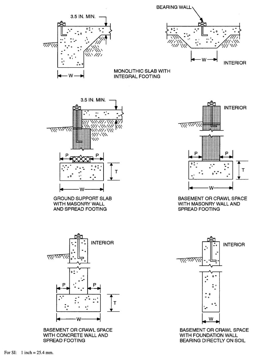
FIGURE R403.1(1)
CONCRETE AND MASONRY FOUNDATION DETAILS
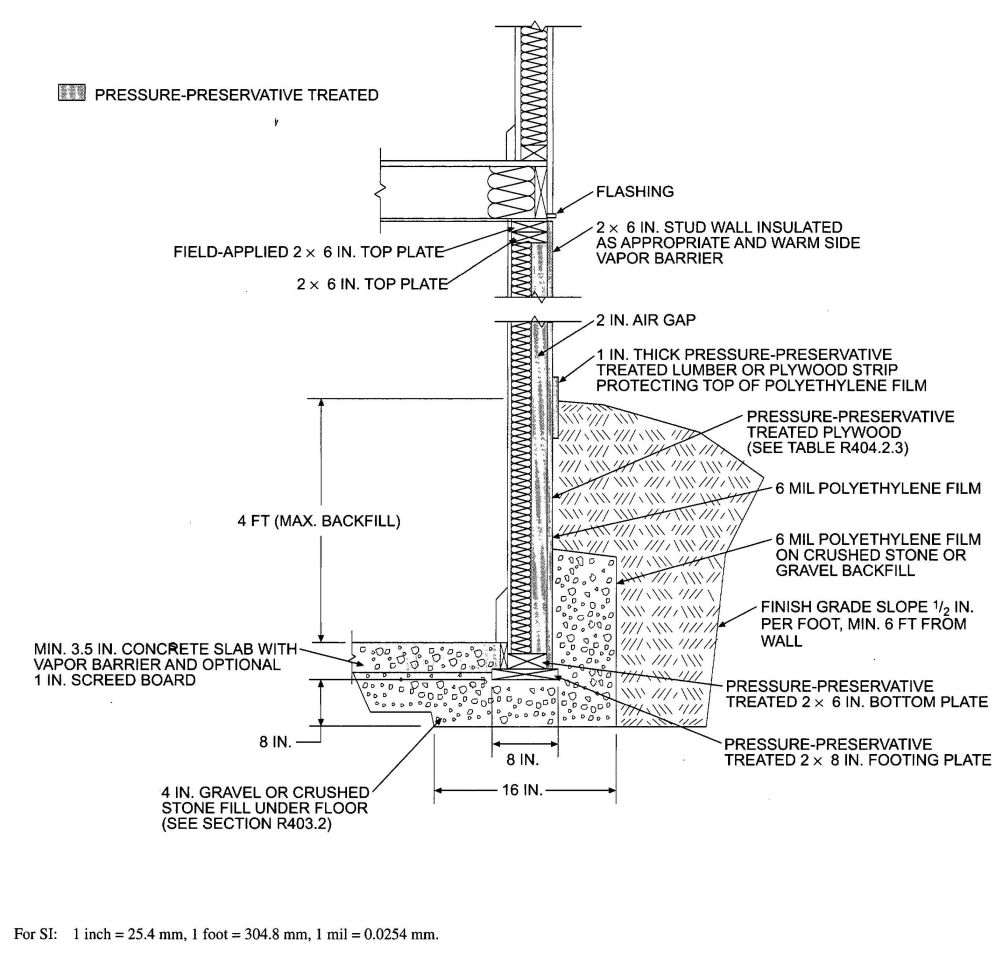
FIGURE R403.1(2)
PERMANENT WOOD FOUNDATION BASEMENT WALL SECTION
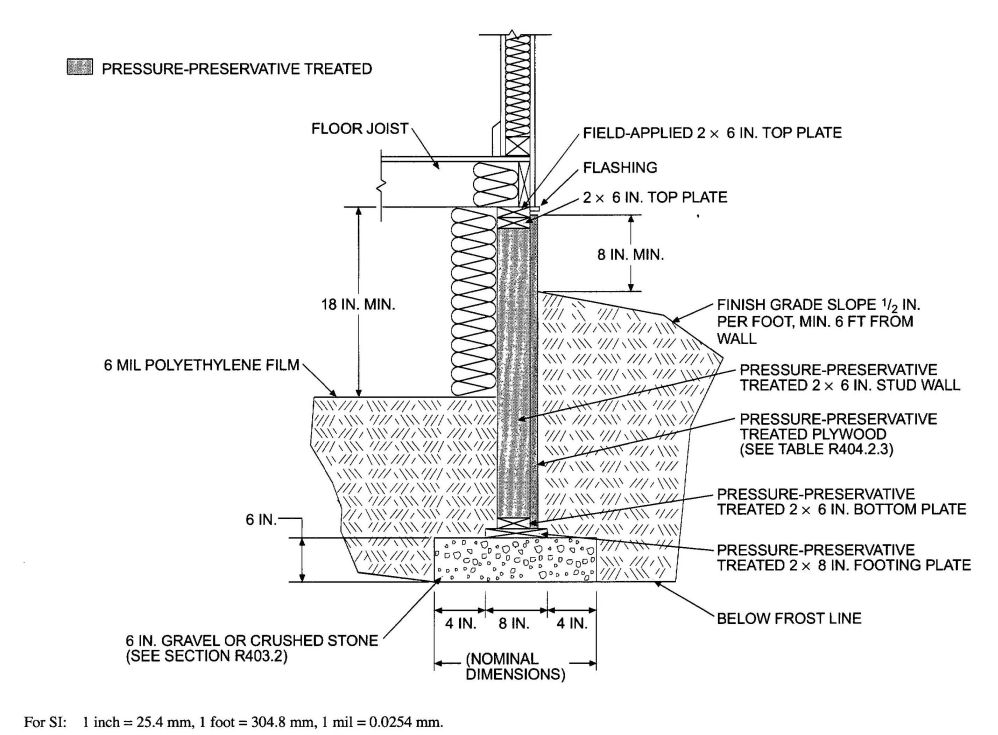
FIGURE R403.1(3)
PERMANENT WOOD FOUNDATION CRAWL SPACE SECTION
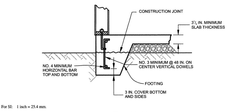
FIGURE R403.1.3.2
DOWELS FOR SLABS-ON-GROUND WITH TURNED-DOWN FOOTINGS
R403.1.4 Minimum depth. All exterior footings shall be placed at least 12 inches (305 mm) below the undisturbed ground surface. Where applicable, the depth of footings shall also conform to Sections R403.1.4.1 through R403.1.4.2.
R403.1.4.1 Frost protection. Except where otherwise protected from frost, foundation walls, piers and other permanent supports of buildings and structures shall be protected from frost by one or more of the following methods:
Exceptions:
Footings shall not bear on frozen soil unless the frozen condition is permanent.
R403.1.4.2 Seismic conditions. In Seismic Design Categories D0, D1 and D2, interior footings supporting bearing or bracing walls and cast monolithically with a slab on grade shall extend to a depth of not less than 12 inches (305 mm) below the top of the slab.
R403.1.5 Slope. The top surface of footings shall be level. The bottom surface of footings shall not have a slope exceeding one unit vertical in 10 units horizontal (10-percent slope). Footings shall be stepped where it is necessary to change the elevation of the top surface of the footings or where the slope of the bottom surface of the footings will exceed one unit vertical in ten units horizontal (10-percent slope).
R403.1.6 Foundation anchorage. Sill plates and walls supported directly on continuous foundations shall be anchored to the foundation in accordance with this section.
Wood sole plates at all exterior walls on monolithic slabs, wood sole plates of braced wall panels at building interiors on monolithic slabs and all wood sill plates shall be anchored to the foundation with anchor bolts spaced a maximum of 6 feet (1829 mm) on center. Bolts shall be at least ½ inch (12.7 mm) in diameter and shall extend a minimum of 7 inches (178 mm) into concrete or grouted cells of concrete masonry units. A nut and washer shall be tightened on each anchor bolt. There shall be a minimum of two bolts per plate section with one bolt located not more than 12 inches (305 mm) or less than seven bolt diameters from each end of the plate section. Interior bearing wall sole plates on monolithic slab foundation that are not part of a braced wall panel shall be positively anchored with approved fasteners. Sill plates and sole plates shall be protected against decay and termites where required by Sections R317 and R318. Cold-formed steel framing systems shall be fastened to wood sill plates or anchored directly to the foundation as required in Section R505.3.1 or R603.3.1.
Exceptions:
R403.1.6.1 Foundation anchorage in Seismic Design Categories C, D0, D1 and D2. In addition to the requirements of Section R403.1.6, the following requirements shall apply to wood light-frame structures in Seismic Design Categories D0, D1 and D2 and wood light-frame townhouses in Seismic Design Category C.
R403.1.7 Footings on or adjacent to slopes. The placement of buildings and structures on or adjacent to slopes steeper than one unit vertical in three units horizontal (33.3-percent slope) shall conform to Sections R403.1.7.1 through R403.1.7.4.
R403.1.7.1 Building clearances from ascending slopes. In general, buildings below slopes shall be set a sufficient distance from the slope to provide protection from slope drainage, erosion and shallow failures. Except as provided in Section R403.1.7.4 and Figure R403.1.7.4.provide this protection. Where the existing slope is steeper than one unit vertical in one unit horizontal (100-percent slope), the toe of the slope shall be assumed to be at the intersection of a horizontal plane drawn from the top of the foundation and a plane drawn tangent to the slope at an angle of 45 degrees (0.79 rad) to the horizontal. Where a retaining wall is constructed at the toe of the slope, the height of the slope shall be measured from the top of the wall to the top of the slope.
R403.1.7.2 Footing setback from descending slope surfaces. Footings on or adjacent to slope surfaces shall be founded in material with an embedment and setback from the slope surface sufficient to provide vertical and lateral support for the footing without detrimental settlement. Except as provided for in Section R403.1.7.4 and Figure R403.1.7.1, the following setback is deemed adequate to meet the criteria. Where the slope is steeper than one unit vertical in one unit horizontal (100-percent slope), the required setback shall be measured from an imaginary plane 45 degrees (0.79 rad) to the horizontal, projected upward from the toe of the slope.
R403.1.7.3 Foundation elevation.On graded sites, the top of any exterior foundation shall extend above the elevation of the street gutter at point of discharge or the inlet of an approveddrainage device a minimum of 12 inches (305 mm) plus 2 percent. Alternate elevations are permitted subject to the approval of the building official, provided it can be demonstrated that required drainage to the point of discharge and away from the structure is provided at all locations on the site.
R403.1.7.4 Alternate setback and clearances. Alternate setbacks and clearances are permitted, subject to the approval of the building official. The building official is permitted to require an investigation and recommendation of a qualified engineer to demonstrate that the intent of this section has been satisfied. Such an investigation shall include consideration of material, height of slope, slope gradient, load intensity and erosion characteristics of slope material.
R403.1.8 Foundations on expansive soils. Foundation and floor slabs for buildings located on expansive soils shall be designed in accordance with Section 1808.6of the California Building Code.
Exception: Slab-on-ground and other foundation systems which have performed adequately in soil conditions similar to those encountered at the building site are permitted subject to the approval of the building official.
R403.1.8.1 Expansive soils classifications. Soils meeting all four of the following provisions shall be compliance with Items 1, 2 and 3 shall not be required if the test prescribed in Item 4 is conducted:
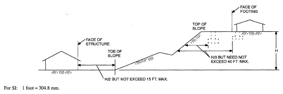
FIGURE R403.1.7.1
FOUNDATION CLEARANCE FROM SLOPES
R403.2 Footings for wood foundations. Footings for wood foundations shall be in accordance with Figures R403.1(2) and R403.1(3). Gravel shall be washed and well graded. The maximum size stone shall not exceed ¾inch (19.1 mm). Gravel shall be free from organic, clayer or silty soils. Sand shall be coarse, not smaller than 1/16-inch (1.6 mm) grains and shall be free from organic, clayer or silty soils. Crushed stone shall have a maximum size of ½ inch (12.7 mm).
R403.3 Frost protected shallow foundations. For buildings where the monthly mean temperature of the building is maintained at a minimum of 64°F (18°C), footings are not required to extend below the frost line when protected from frost by insulation in accordance with Figure R403.3(1) and Table R403.3(1). shall not be used for unheated spaces such as porches, utility rooms, garages and carports, and shall not be attached to basements or crawl spaces that are not maintained at a minimum monthly mean temperature of 64°F (18°C).
Materials used below grade for the purpose of insulating footings against frost shall be labeledas complying with ASTM C 578.
R403.3.1 Foundation adjoining frost protected shallow foundations. Foundations that adjoin frost protected shallow foundations shall be protected from frost in accordance with Section R403.1.4.
R403.3.1.1 Attachment to unheated slab-on-ground structure. Vertical wall insulation and horizontal insulation of frost protected shallow foundations that adjoin a slab-on-ground foundation that does not have a monthly mean temperature maintained at a minimum of 64°F (18°C) shall be in accordance with Figure R403.3(3) and Table R403.3(1). Vertical wall insulation shall extend between the frost protected shallow foundation and the adjoining slab foundation. Required horizontal insulation shall be continuous under the adjoining slab foundation and through any foundation walls adjoining the frost protected shallow foundation. Where insulation passes through a foundation wall, it shall either be of a type complying with this section and having bearing loads imposed by the building, or the building shall be designed and constructed using beams, lintels, cantilevers or other means of transferring building loads such that the structural loads of the building do not bear on the insulation.
R403.3.1.2 Attachment to heated structure. Where a frost protected shallow foundation abuts a structure that has a monthly mean temperature maintained at a minimum of 64°F (18°C), horizontal insulation and vertical wall insulation shall not be required between the frost protected shallow foundation and the adjoining structure. Where the frost protected shallow foundation abuts the heated structure, the horizontal insulation and vertical wall insulation shall extend along the adjoining foundation in accordance with Figure R403.3(4) a distance of not less than Dimension A in Table R403.3(1).
Exception: Where the frost protected shallow foundation abuts the heated structure to form an inside corner, vertical insulation extending along the adjoining foundation is not required.
R403.3.2 Protection of horizontal insulation below the ground. Horizontal insulation placed less than 12 inches (305 mm) below the ground surface or that portion of horizontal insulation extending outward more than 24 inches (610 mm) from the foundation edge shall be protected against damage by use of a concrete slab or asphalt paving on the ground surface directly above the insulation or by cementitious board, plywood rated for below-ground use, or other approved materials placed below ground, directly above the top surface of the insulation.
R403.3.3 Drainage. Final grade shall be sloped in accordance with Section R401.3. In other than Group I Soils, as detailed in Table R405.1, gravel or crushed stone beneath horizontal insulation below ground shall drain to daylight or into an approved sewer system.
R403.3.4 Terminate damage. The use of foam plastic in areas of “very heavy” terminate infestation probability shall be in accordance with Section R318.4.
R403.4 Footings for percast concrete foundations. Footings for precast concrete foundations shall comply with Section R403.4.
R403.4.1 Crushed stone footings. Clean crushed stone shall be free from organic, clayey or silty soils. Crushed stone shall be angular in nature and meet ASTM C 33, with the maximum size stone not to exceed ½ inch (12.7 mm) and the minimum stone size not to be smaller than 1/16-inch (1.6 mm). Crushed stone footings for precast foundations shall be installed in accordance with Figure R403.4(1) and Table R403.4. Crushed stone footings shall be consolidated using a vibratory plate in a maximum of 8-inch lifts. Crushed stone footings shall be limited to Seismic Design Categories A, B and C.
R403.4.2 Concrete footings. Concrete footings shall be installed in accordance with Section R403.1 and Figure R403.4(2).
R404.1 Concrete and masonry foundation walls.Concrete foundation walls shall be selected and constructed in accordance with the provisions of Section R404.1.2.Masonry foundation walls shall be selected and constructed in accordance with the provisions of Section R404.1.1.
R404.1.1 Design of masonry foundation walls. Masonry foundation walls shall be designed and constructed in accordance with the provisions of this section or in accordance with the provisions of ACI530/ASCE 5/TMS 402 or NCMA TR68-A. When ACI530/ASCE 5/TMS 402, NCMA TR68-A or the provisions of this section are used to design masonry foundation walls, project drawings, typical details and specifications are not required to bear the seal of the architect or engineer responsible for design, unless otherwise required by the state law of the jurisdiction having authority.
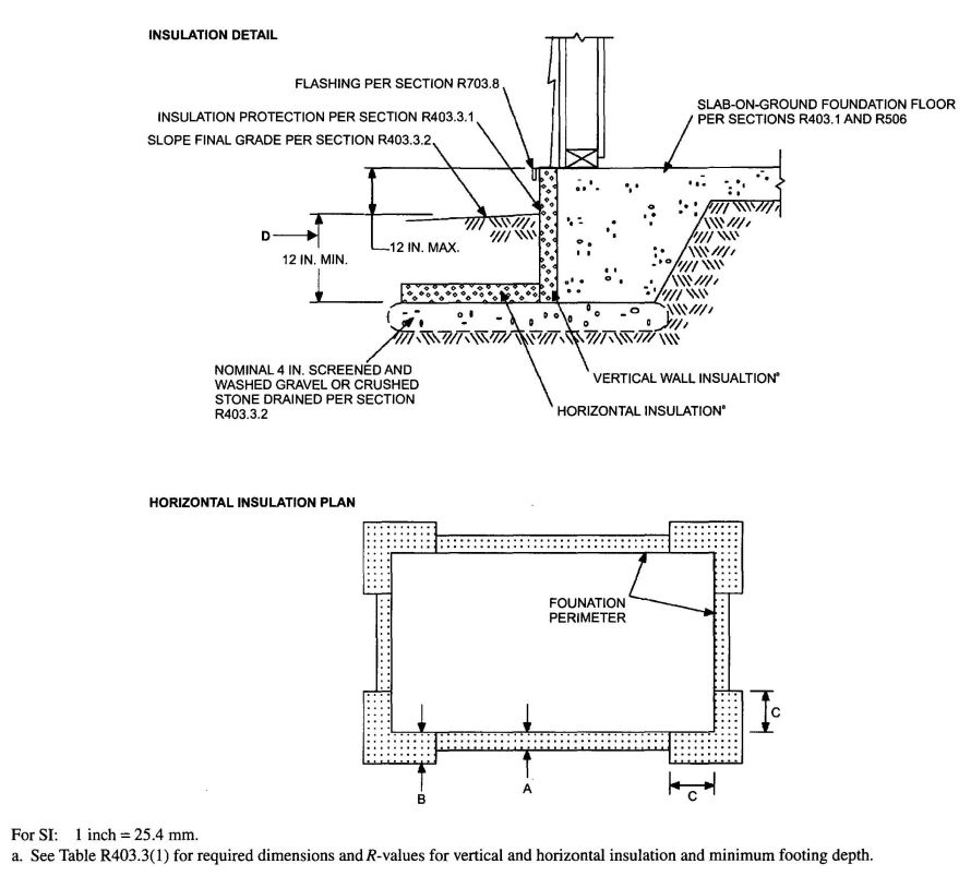
FIGURE R403.3(1)
INSULATION PLACEMENT FOR FROST PROTECTED FOOTINGS IN HEATED BUILDINGS
| AIR FREEZING INDEX (°F-days)b | MINIMUM FOOTING DEPTH, D (Inches) |
VERTICAL INSULATION R-VALUEc,d | HORIZONTAL INSULATION R-VALUEc,e | HORIZONTAL INSULATION DIMENSIONS PER FIGURE R403.3(1) (inches) | |||
|---|---|---|---|---|---|---|---|
| Along walls | At corners | A | B | C | |||
| a. Insulation requirements are for protection against frost damage in heated buildings. Greater values may be required to meet energy conservation standards. | |||||||
| b. See Figure R403.3(2) or Table R403.3(2) for Air Freezing Index values. | |||||||
| c. Insulation materials shall provide the stated minimum R-values under long-term exposure to moist, below-ground conditions in freezing climates. The following R-values shall be used to determine insulation thickness required for this application: Type II expanded polystyrene—2.4R per inch; Type IV extruded polystyrene—4.5R per inch; Type VI extruded polystyrene—4.5R per inch; Type IX expanded polystyrene—3.2Rper inch; Type X extruded polystyrene—R per inch. | |||||||
| d. Vertical insulation shall be expanded polystyrene insulation or extruded polystyrene insulation. | |||||||
| e. Horizontal insulation shall be extruded polystyrene insulation. | |||||||
| 1,500 or less | 12 | 4.5 | Not required | Not required | Not required | Not required | Not required |
| 2,000 | 14 | 5.6 | Not required | Not required | Not required | Not required | Not required |
| 2,500 | 16 | 6.7 | 1.7 | 4.9 | 12 | 24 | 40 |
| 3,000 | 16 | 7.8 | 6.5 | 8.6 | 12 | 24 | 40 |
| 3,500 | 16 | 9.0 | 8.0 | 11.2 | 24 | 30 | 60 |
| 4,000 | 16 | 10.1 | 10.5 | 13.1 | 24 | 36 | 60 |
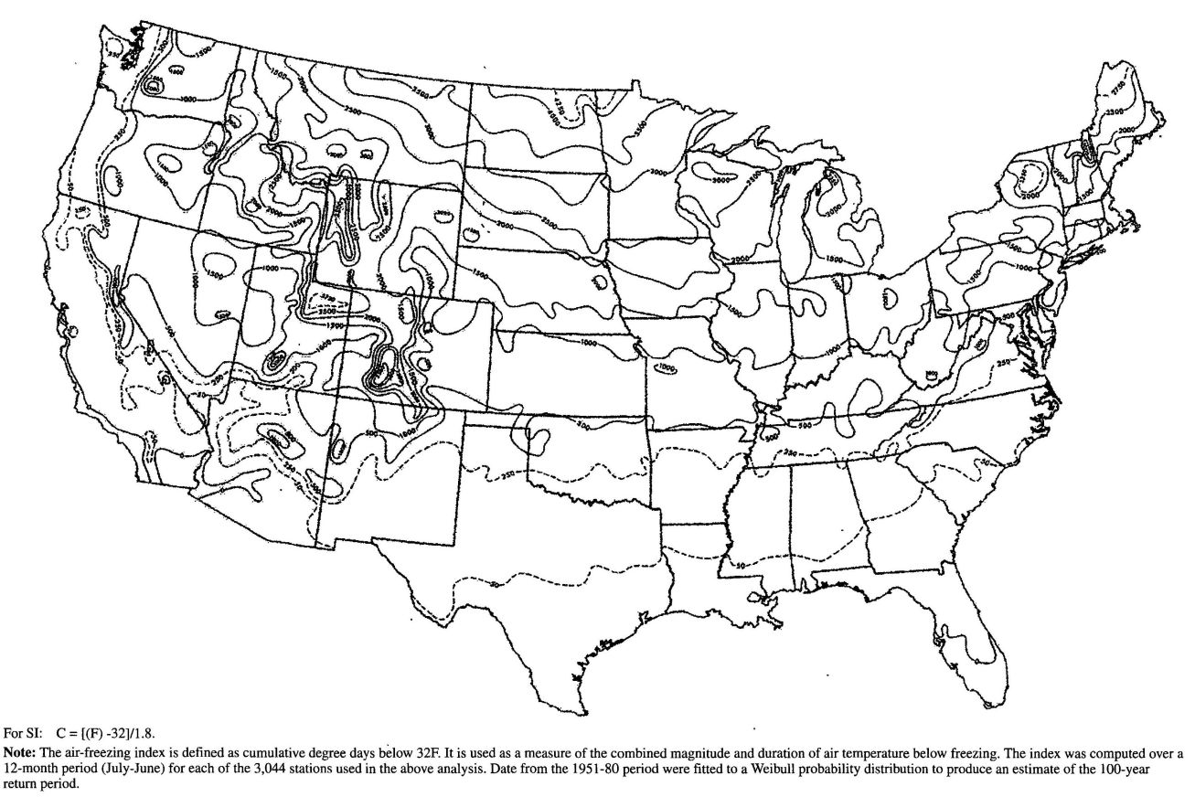
FIGURE R403.3(2)
AIR-FREEZING INDEX AN ESTIMATE OF THE 100-YEAR RETURN PERIOD
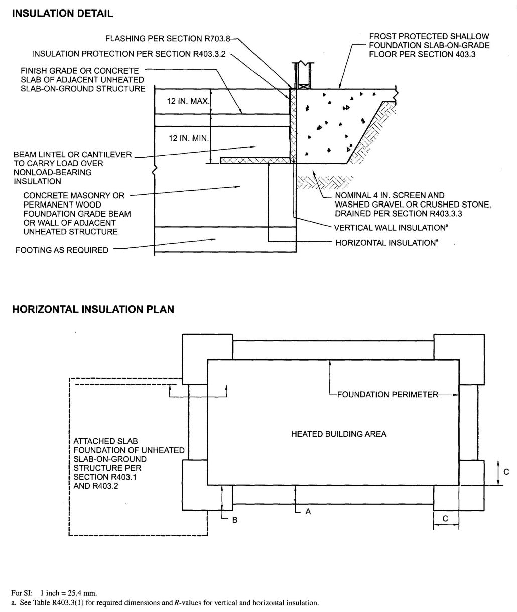
FIGURE R403.3(3)
INSULATION PLACEMENT FOR FROST-PROTECTED FOOTINGS ADJACENT TO UNHEATED SLAB-ON-GROUND STRUCTURE
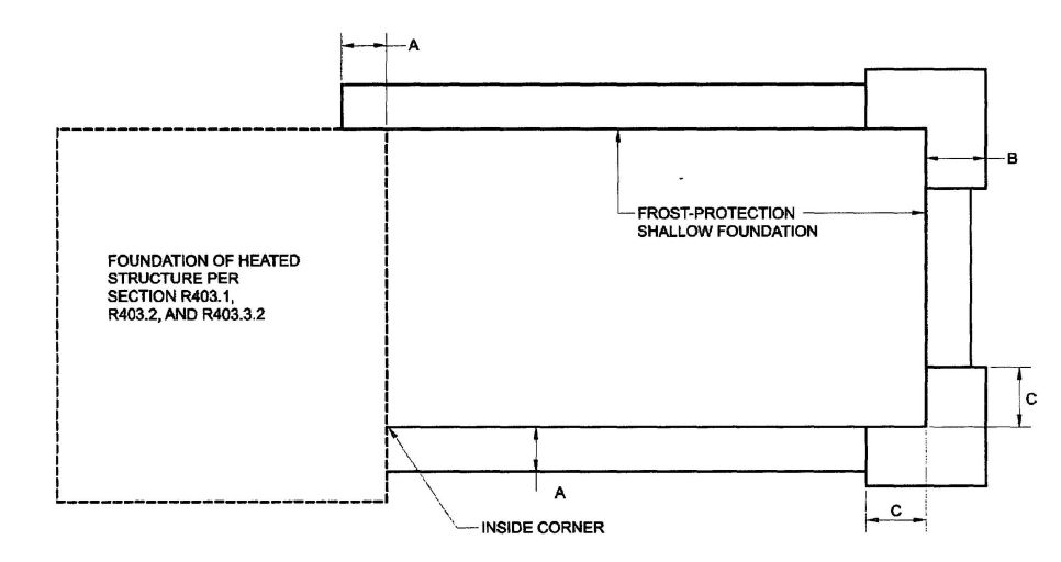
FIGURE R403.3(4)
INSULATION PLACEMENT FOR FROST-PROTECTED FOOTINGS ADJACENT TO HEATED STRUCTURE
| LOAD BEARING VALUE OF SOIL (psf) | |||||||||||||||||
|---|---|---|---|---|---|---|---|---|---|---|---|---|---|---|---|---|---|
| 1500 | 2000 | 3000 | 4000 | ||||||||||||||
| MH, CH, CL, ML | SC, GC, SM, GM, SP, SW | GP, GW | |||||||||||||||
| Wall width (inches) | Wall width (inches) | Wall width (inches) | Wall width (inches) | ||||||||||||||
| 6 | 8 | 10 | 12 | 6 | 8 | 10 | 12 | 6 | 8 | 10 | 12 | 6 | 8 | 10 | 12 | ||
| Conventional light-frame construction | |||||||||||||||||
| For SI: 1 inch=25.4 mm, 1 pound per square inch=6.89 kPa. | |||||||||||||||||
| 1-story | 1100 plf | 6 | 4 | 4 | 4 | 6 | 4 | 4 | 4 | 6 | 4 | 4 | 4 | 6 | 4 | 4 | 4 |
| 2-story | 1800 plf | 8 | 6 | 4 | 4 | 6 | 4 | 4 | 4 | 6 | 4 | 4 | 4 | 6 | 4 | 4 | 4 |
| 3-story | 2000 plf | 16 | 14 | 12 | 10 | 10 | 8 | 6 | 6 | 6 | 4 | 4 | 4 | 6 | 4 | 4 | 4 |
| 4-inch brick veneer over fight-frame or 8-inch hollow concrete masonry | |||||||||||||||||
| 1-story | 1500 plf | 6 | 4 | 4 | 4 | 6 | 4 | 4 | 4 | 6 | 4 | 4 | 4 | 6 | 4 | 4 | 4 |
| 2-story | 2700 plf | 14 | 12 | 10 | 8 | 10 | 8 | 6 | 4 | 6 | 4 | 4 | 4 | 6 | 4 | 4 | 4 |
| 3-story | 4000 plf | 22 | 22 | 20 | 18 | 16 | 14 | 12 | 10 | 10 | 8 | 6 | 4 | 6 | 4 | 4 | 4 |
| 8-inch solid or fully grouted masonry | |||||||||||||||||
| 1-story | 2000 plf | 10 | 8 | 6 | 4 | 6 | 4 | 4 | 4 | 6 | 4 | 4 | 4 | 6 | 4 | 4 | 4 |
| 2-story | 3600 plf | 20 | 18 | 16 | 16 | 14 | 12 | 10 | 8 | 8 | 6 | 4 | 4 | 6 | 4 | 4 | 4 |
| 3-story | 5300 plf | 32 | 30 | 28 | 26 | 22 | 22 | 20 | 18 | 14 | 12 | 10 | 8 | 10 | 8 | 6 | 4 |
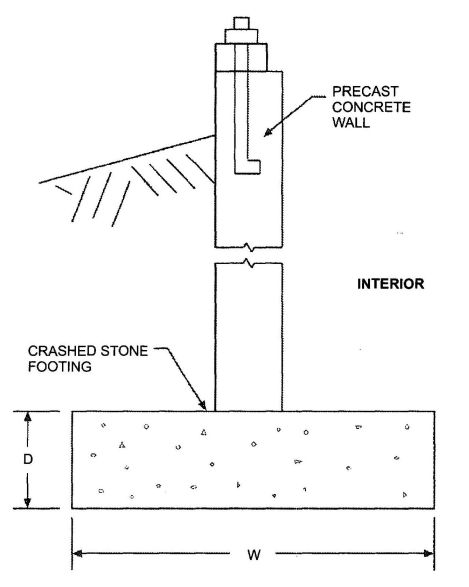
FIGURE R403.4(1)
BASEMENT OR CRAWL SPACE WITH PRECAST FOUNDATION WALL BEARING ON CRUSHED STONE
R404.1.1.1 Masonry foundation walls. Concrete masonry and clay masonry foundation walls shall be constructed as set forth in Table R404.1.1(1), R404.1.1(2), R404.1.1(3) or R404.1.1(4) and shall also comply with applicable provisions of Sections R606, R607 and R608. In buildings assigned to Seismic Design Categories D0, D1 and D2, concrete masonry and clay masonry foundation walls shall also comply with Section R404.1.4.1. Rubble stone masonry foundation walls shall be constructed in accordance with Sections R404.1.8 and R607.2.2. Rubble stone masonry walls shall not be used in Seismic Design Categories D0, D1 and D2.
R404.1.2 Concrete foundation walls. Concrete foundation walls that support light-frame walls shall be designed and constructed in accordance with the provisions of this section, ACI 318, ACI 332 or PCA 100. Concrete foundation walls that support above-grade concrete walls that are within the applicability limits of Section R611.2 shall be designed and constructed in accordance with the provisions of this section, ACI 318, ACI 332 or PCA 100. Concrete foundation walls that support above-grade concrete walls that are not within the applicability limits of Section R611.2 shall be designed and constructed in accordance with the provisions of ACI 318, ACI 332 or PCA 100. When ACI 318, ACI 332, PCA 100 or the provisions of this section are used to design concrete foundation walls, project drawings, typical details and specifications are not required to bear the scal of the architect
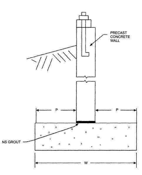
FIGURE R403.4(2)
BASEMENT OR CRAWL SPACE WITH PRECAST FOUNDATION WALL ON SPREAD FOOTING
or engineer responsible for design, unless otherwise required by the state law of the jurisdiction having authority.
R404.1.2.1 Concrete cross-section. Concrete walls constructed in accordance with this code shall comply with the shapes and minimum concrete cross-sectional dimensions required by Table R611.3. Other types of forming systems resulting in concrete walls not in compliance with this section and Table R611.3 shall be designed in accordance with ACI 318.
R404.1.2.2 Reinforcement for foundation walls. Concrete foundation walls shall be laterally supported at the top and bottom. Horizontal reinforcement shall be provided in accordance with Table R404.1.2(1). Vertical reinforcement shall be provided in accordance with Table R404.1.2(2), R404.1.2(3), R404.1.2(4), R404.1.2(5), R404.1.2(6), R404.1.2(7) or R404.1.2(8). Vertical reinforcement for flat basement walls retaining 4 feet (1219 mm) or more of unbalanced backfill is permitted to be determined in accordance with Table R404.1.2(9). For basement walls supporting above-grade concrete walls, vertical reinforcement shall be the greater of that required by Tables R404.1.2(2) through R404.1.2(8) or by Section R611.6 for the above-grade wall. In buildings assigned to Seismic Design Category D0, D1 or D2, concrete foundation walls shall also comply with Section R404.1.4.2.
| MAXIMUM WALL HEIGHT (feet) | MAXIMUM UNBALANCED BACKFILL HEIGHTc (feet) | PLAIN MASONRYa MINIMUM NOMINAL WALL THICKNESS (inches) | ||
|---|---|---|---|---|
| Soll classesb | ||||
| GW, GP, SW and SP | GM, GC, SM, SM-SC and ML | SC, MH, ML-CL and inorganic CL | ||
| For SI: 1 inch = 25.4 mm, 1 foot = 304.8 mm, 1 pound per square inch = 6.895 Pa. | ||||
| a. Mortar shall be Type M or S and masonry shall be laid in running bond. Ungrouted hollow masonry units are permitted except where otherwise indicated. | ||||
| b. Soil classes are in accordance with the Unified Soil Classification System. Refer to Table R405.1. | ||||
| c. Unbalanced backfill height is the difference in height between the exterior finish ground level and the lower of the top of the concrete footing that supports the foundation wall or the interior finish ground level. Where an interior concrete slab-on-grade is provided and is in contact with the interior surface of the foundation wall, measurement of the unbalanced backfill height from the exterior finish ground level to the top of the interior concrete slab is permitted. | ||||
| d. Solid grouted hollow units or solid masonry units. | ||||
| e. Wall construction shall be in accordance with either Table R404.1.1(2), Table R404.1.1(3), Table R404.1.1(4), or a design shall be provided. | ||||
| 5 | 4 | 6 solidd or 8 | 6 solidd or 8 | 6 solidd or 8 |
| 5 | 6 solidd or 8 | 8 | 10 | |
| 6 | 4 | 6 solidd or 8 | 6 solidd or 8 | 6 solidd or 8 |
| 5 | 6 solidd or 8 | 8 | 10 | |
| 6 | 8 | 10 | 12 | |
| 7 | 4 | 6 solidd or 8 | 8 | 8 |
| 5 | 6 solidd or 8 | 10 | 10 | |
| 6 | 10 | 12 | 10 solidd | |
| 7 | 12 | 10 solidd | 12 solidd | |
| 8 | 4 | 6 solidd or 8 | 6 solidd or 8 | 8 |
| 5 | 6 soliddor 8 | 10 | 12 | |
| 6 | 10 | 12 | 12 solidd | |
| 7 | 12 | 12 solidd | Footnote e | |
| 8 | 10 solidd | 12 solidd | Footnote e | |
| 9 | 4 | 6 solidd or 8 | 6 solidd or 8 | 8 |
| 5 | 8 | 10 | 12 | |
| 6 | 10 | 12 | 12 solidd | |
| 7 | 12 | 6 solidd | Footnote e | |
| 8 | 12 solidd | Footnote e | Footnote e | |
| 9 | Footnote e | Footnote e | Footnote e | |
| WALL HEIGHT | HEIGHT OF UNBALANCED BACKFILLe | MINIMUM VERTICAL REINFORCEMENT AND SPACING (INCHES)b,c | ||
|---|---|---|---|---|
| Soil classes and lateral soil loadd (psf per foot below grade) | ||||
| GW, GP, SW and SP soils 30 | GM, GC, SM, SM-SC and ML soils 45 | SC, ML-CL and inorganic CL soils 60 | ||
| For SI: 1 inch = 25.4 mm, 1 foot = 304.8 mm, 1 pound per square foot per foot = 0.157 kPa/mm. | ||||
| a. Mortar shall be Type M or S and masonry shall be laid in running bond. | ||||
| b. Alternative reinforcing bar sizes and spacings having an equivalent cross-sectional area of reinforcement per linedal foot of wall shall be permitted provided the spacing of the reinforcement does not exceed 72 inches. | ||||
| c. Vertical reinforcement shall be Grade 60 minimum. The distance, d, from the face of the soil side of the wall to the center of vertical reinforcement shall be at least 5 inches. | ||||
| d. Soil classes are in accordance with the Unified Soil Classification System and design lateral soil loads are for moist conditions without hydrostatic pressure. Refer to Table R405.1. | ||||
| e. Unbalanced backfill height is the difference in height between the exterior finish ground level and the lower of the top of the concrete footing that supports the foundation wall or the interior finish ground level. Where an interior concrete slab-on-grade is provided and is in contact with the interior surface of the foundation wall, measurement of the unbalanced backfill height from the exterior finish ground level to the top of the interior concrete slab is permitted. | ||||
| 6 feet 8 inches | 4 feet (or less) | #4 at 48 | #4 at 48 | #4 at 48 |
| 5 feet | #4 at 48 | #4 at 48 | #4 at 48 | |
| 6 feet 8 inches | #4 at 48 | #5 at 48 | #6 at 48 | |
| 7 feet 4 inches | 4 feet (or less) | #4 at 48 | #4 at 48 | #4 at 48 |
| 5 feet | #4 at 48 | #4 at 48 | #4 at 48 | |
| 6 feet | #4 at 48 | #5 at 48 | #5 at 48 | |
| 7 feet 4 inches | #5 at 48 | #6 at 48 | #6 at 40 | |
| 8 feet | 4 feet (or less) | #4 at 48 | #4 at 48 | #4 at 48 |
| 5 feet | #4 at 48 | #4 at 48 | #4 at 48 | |
| 6 feet | #4 at 48 | #5 at 48 | #5 at 48 | |
| 7 feet | #5 at 48 | #6 at 48 | #6 at 40 | |
| 8 feet | #5 at 48 | #6 at 48 | #6 at 32 | |
| 8 feet 8 inches | 4 feet (or less) | #4 at 48 | #4 at 48 | #4 at 48 |
| 5 feet | #4 at 48 | #4 at 48 | #5 at 48 | |
| 6 feet | #4 at 48 | #5 at 48 | #6 at 48 | |
| 7 feet | #5 at 48 | #6 at 48 | #6 at 40 | |
| 8 feet 8 inches | #6 at 48 | #6 at 32 | #6 at 4 | |
| 9 feet 9 inches | 4 feet (or less) | #4 at 48 | #4 at 48 | #4 at 48 |
| 5 feet | #4 at 48 | #4 at 48 | #5 at 48 | |
| 6 feet | #4 at 48 | #5 at 48 | #6 at 48 | |
| 7 feet | #5 at 48 | #6 at 48 | #6 at 40 | |
| 8 feet | #6 at 48 | #6 at 40 | #6 at 24 | |
| 9 feet 4 inches | #6 at 40 | #6 at 24 | #6 at 16 | |
| 10 feet | 4 feet (or less) | #4 at 48 | #4 at 48 | #4 at 48 |
| 5 feet | #4 at 48 | #4 at 48 | #5 at 48 | |
| 6 feet | #4 at 48 | #5 at 48 | #6 at 48 | |
| 7 feet | #5 at 48 | #6 at 48 | #6 at 32 | |
| 8 feet | #6 at 48 | #6 at 32 | #6 at 24 | |
| 9 feet | #6 at 40 | #6 at 24 | #6 at 16 | |
| 10 feet | #6 at 32 | #6 at 16 | #6 at 16 | |
| WALL HEIGHT | HEIGHT OF UNBALANCED BACKFILLe | MINIMUM VERTICAL REINFORCEMENT AND SPACING (INCHES)b,c | ||
|---|---|---|---|---|
| Soil classes and later soil loadd (psf per foot below grade) | ||||
| GW, GP, SW and SP soils 30 | GM, GC, SM, SM-SC and ML soils 45 | SC, ML-CL and inorganic CL soils 60 | ||
| For SI: 1 inch = 25.4 mm, 1 foot = 304.8 mm, 1 pound per square foot per foot = 0.157 kPa/mm. | ||||
| a. Mortar shall be Type M or S and masonry shall be laid in running bond. | ||||
| b. Alternative reinforcing bar sizes and spacings having an equivalent cross-sectional area of reinforcement per lineal foot of wall shall be permitted provided the spacing of the reinforcement does not exceed 72 inches. | ||||
| c. Vertical reinforcement shall be Grade 60 minimum. The distance, d, from the face of the soil side of the wall to the center of vertical reinforcement shall be at least 6.75 inches. | ||||
| d. Soil classes are in accordance with the Unified Soil Classification System and design lateral soil loads are for moist conditions without hydrostatic pressure. Refer to Table R405.1. | ||||
| e. Unbalanced backfill height is the difference in height between the exterior finish ground level and the lower of the top of the concrete footing that supports the foundation wall or the interior finish ground level. Where an interior concrete slab-on-grade is provided and is in contact with the interior surface of the foundation wall, measurement of the unbalanced backfill height from the exterior finish ground level to the top of the interior concrete slab is permitted. | ||||
| 6 feet 8 inches | 4 feet (or less) | #4 at 56 | #4 at 56 | #4 at 56 |
| 5 feet | #4 at 56 | #4 at 56 | #4 at 56 | |
| 6 feet 8 inches | #4 at 56 | #5 at 56 | #5 at 56 | |
| 7 feet 4 inches | 4 feet (or less) | #4 at 56 | #4 at 56 | #4 at 56 |
| 5 feet | #4 at 56 | #4 at 56 | #4 at 56 | |
| 6 feet | #4 at 56 | #4 at 56 | #5 at 56 | |
| 7 feet 4 inches | #4 at 56 | #5 at 56 | #6 at 56 | |
| 8 feet | 4 feet (or less) | #4 at 56 | #4 at 56 | #4 at 56 |
| 5 feet | #4 at 56 | #4 at 56 | #4 at 56 | |
| 6 feet | #4 at 56 | #4 at 56 | #5 at 56 | |
| 7 feet | #4 at 56 | #5 at 56 | #6 at 56 | |
| 8 feet | #5 at 56 | #6 at 56 | #6 at 48 | |
| 8 feet 8 inches | 4 feet (or less) | #4 at 56 | #4 at 56 | #4 at 56 |
| 5 feet | #4 at 56 | #4 at 56 | #4 at 56 | |
| 6 feet | #4 at 56 | #5 at 56 | #5 at 56 | |
| 7 feet | #4 at 56 | #5 at 56 | #6 at 56 | |
| 8 feet 8 inches | #5 at 56 | #6 at 48 | #6 at 32 | |
| 9 feet 4 inches | 4 feet (or less) | #4 at 56 | #4 at 56 | #4 at 56 |
| 5 feet | #4 at 56 | #4 at 56 | #4 at 56 | |
| 6 feet | #4 at 56 | #5 at 56 | #5 at 56 | |
| 7 feet | #4 at 56 | #5 at 56 | #6 at 56 | |
| 8 feet | #5 at 56 | #6 at 56 | #6 at 40 | |
| 9 feet 4 inches | #6 at 56 | #6 at 40 | #6 at 24 | |
| 10 feet | 4 feet (or less) | #4 at 56 | #4 at 56 | #4 at 56 |
| 5 feet | #4 at 56 | #4 at 56 | #4 at 56 | |
| 6 feet | #4 at 56 | #5 at 56 | #5 at 56 | |
| 7 feet | #5 at 56 | #6 at 56 | #6 at 48 | |
| 8 feet | #5 at 56 | #6 at 48 | #6 at 40 | |
| 9 feet | #6 at 56 | #6 at 40 | #6 at 24 | |
| 10 feet | #6 at 48 | #6 at 32 | #6 at 24 | |
| WALL HEIGHT | HEIGHT OF UNBALANCED BACKFILLe | MINIMUM VERTICAL REINFORCEMENT AND SPACING (INCHES)b,c | ||
|---|---|---|---|---|
| Soil classes and lateral soil loadd (psf per foot below grade) | ||||
| GW, GP, SW and SP soils 30 | GM, GC, SM, SM-SC and ML soils 45 | SC, ML-CL and inorganic CL soils 60 | ||
| For SI: 1 inch = 25.4 mm, 1 foot = 304.8 mm, 1 pound per square foot per foot = 0.157 kPa/mm. | ||||
| a. Mortar shall be Type M or S and masonry shall be laid in running bond. | ||||
| b. Alternative reinforcing bar sizes and spacings having an equivalent cross-sectional area of reinforcement per lineal foot of wall shall be permitted provided the spacing of the reinforcement does not exceed 72 inches. | ||||
| c. Vertical reinforcement shall be Grade 60 minimum. The distance, d, from the face of the soil side of the wall to the center of vertical reinforcement shall be at least 8.75 inches. | ||||
| d. Soil classes are in accordance with the Unified Soil Classification System and design lateral soil loads are for moist conditions without hydrostatic pressure. Refer to Table R405.1. | ||||
| e. Unbalanced backfill height is the difference in height between the exterior finish ground level and the lower of the top of the concrete footing that supports the foundation wall or the interior finish ground levels. Where an interior concrete slab-on-grade is provided and in contact with the interior surface of the foundation wall, measurement of the unbalanced backfill height is permitted to be measured from the exterior finish ground level to the top of the interior concrete slab is permitted. | ||||
| 6 feet 8 inches | 4 feet (or less) | #4 at 72 | #4 at 72 | #4 at 72 |
| 5 feet | #4 at 72 | #4 at 72 | #4 at 72 | |
| 6 feet 8 inches | #4 at 72 | #4 at 72 | #5 at 72 | |
| 7 feet 4 inches | 4 feet (or less) | #4 at 72 | #4 at 72 | #4 at 72 |
| 5 feet | #4 at 72 | #4 at 72 | #4 at 72 | |
| 6 feet | #4 at 72 | #4 at 72 | #5 at 72 | |
| 7 feet 4 inches | #4 at 72 | #5 at 72 | #6 at 72 | |
| 8 feet | 4 feet (or less) | #4 at 72 | #4 at 72 | #4 at 72 |
| 5 feet | #4 at 72 | #4 at 72 | #4 at 72 | |
| 6 feet | #4 at 72 | #4 at 72 | #5 at 72 | |
| 7 feet | #4 at 72 | #5 at 72 | #6 at 72 | |
| 8 feet | #5 at 72 | #6 at 72 | #6 at 64 | |
| 8 feet 8 inches | 4 feet (or less) | #4 at 72 | #4 at 72 | #4 at 72 |
| 5 feet | #4 at 72 | #4 at 72 | #4 at 72 | |
| 6 feet | #4 at 72 | #4 at 72 | #5 at 72 | |
| 7 feet | #4 at 72 | #5 at 72 | #6 at 72 | |
| 8 feet 8 inches | #5 at 72 | #7 at 72 | #6 at 48 | |
| 9 feet 4 inches | 4 feet (or less) | #4 at 72 | #4 at 72 | #4 at 72 |
| 5 feet | #4 at 72 | #4 at 72 | #4 at 72 | |
| 6 feet | #4 at 72 | #5 at 72 | #5 at 72 | |
| 7 feet | #4 at 72 | #5 at 72 | #6 at 72 | |
| 8 feet | #5 at 72 | #6 at 72 | #6 at 56 | |
| 9 feet 4 inches | #6 at 72 | #6 at 48 | #6 at 40 | |
| 10 feet | 4 feet (or less) | #4 at 72 | #4 at 72 | #4 at 72 |
| 5 feet | #4 at 72 | #4 at 72 | #4 at 72 | |
| 6 feet | #4 at 72 | #5 at 72 | #5 at 72 | |
| 7 feet | #4 at 72 | #6 at 72 | #6 at 72 | |
| 8 feet | #5 at 72 | #6 at 72 | #6 at 48 | |
| 9 feet | #6 at 72 | #6 at 56 | #6 at 40 | |
| 10 feet | #6 at 64 | #6 at 40 | #6 at 32 | |
| MAXIMUM UNSUPPORTEDHEIGHT OF BASEMENT WALL(feet) | LOCATION OF HORIZONTAL REINFORCEMENT |
|---|---|
| For SI: 1 inch = 25.4 mm, 1 foot = 304.8 mm, 1 pound per square inch = 6.895 kPa. | |
| a. Horizontal reinforcement requirements are for reinforcing bars with a minimum yield strength of 40,000 psi and concrete with a minimum concrete compressive strength 2,500 psi. | |
| b. See Section R404.1.2.2 for minimum reinforcement required for foundation walls supporting above-grade concrete walls. | |
| ≤ 8 | One No. 4 bar within 12 inches of the top of the wall story and one No. 4 bar near mid-height of the wall story |
| > 8 | One No. 4 bar within 12 inches of the top of the wall story and one No. 4 bar near third points in the wall story |
| MAXIMUM UNSUPPORTED WALL HEIGHT (feet) | MAXIMUM UNBALANCED BACKFILL HEIGHT1 (feet) | MINIMUM VERTICAL REINFORCEMENT—BAR SIZE AND SPACING (inches) | ||
|---|---|---|---|---|
| Soil classesa and design lateral soil (psf per foot of depth) | ||||
| GW, GP, SW, SP 30 | GM, GC, SM, SM-SC and ML 45 | SC, ML-CL and inorganic CL 60 | ||
| For SI:1 foot = 304.8 mm; 1 inch = 25.4 mm; 1 pound per square foot per foot = 0.1571 kPa2⁄m, 1 pound per square inch = 6.895 kPa. | ||||
| a. Soil classes are in accordance with the Unified Soil Classification System. Refer to Table R405.1. | ||||
| b. Table values are based on reinforcing bars with a minimum yield strength of 60,000 psi concrete with a minimum specified compressive strength of 2,500 psi and vertical reinforcement being located at the centerline of the wall. See Section R404.1.2.3.7.2. | ||||
| c. Vertical reinforcement with a yield strength of less than 60,000 psi and⁄or bars of a different size than specified in the tables are permitted in accordance with Section R404.1.2.3.7.6 and Table R404.1.2(9). | ||||
| d. Deflection criterion is L⁄240, where L is the height of the basement wall in inches. | ||||
| e. Interpolation is not permitted. | ||||
| f. Where walls will retain 4 feet or more of unbalanced backfill, they shall be laterally supported at the top and bottom before backfilling. | ||||
| g. NR indicates no vertical wall reinforcement is required, except for 6-inch nominal walls formed with stay-in-place forming systems in which case vertical reinforcement shall be No.4@48 inches on center. | ||||
| h. See Section R404.1.2.2 for minimum reinforcement required for basement walls supporting above-grade concrete walls. | ||||
| i. See Table R611.3 for tolerance from nominal thickness permitted for flat walls. | ||||
| j. DR means design is required in accordance with the applicable building code, or where there is no code, in accordance with ACI 318. | ||||
| 8 | 4 | NR | NR | NR |
| 5 | NR | 6 @ 39 | 6 @ 48 | |
| 6 | 5 @ 39 | 6 @ 48 | 6 @ 35 | |
| 7 | 6 @ 48 | 6 @ 34 | 6 @ 25 | |
| 8 | 6 @ 39 | 6 @ 25 | 6 @ 18 | |
| 9 | 4 | NR | NR | NR |
| 5 | NR | 5 @ 37 | 6 @ 48 | |
| 6 | 5 @ 36 | 6 @ 44 | 6 @ 32 | |
| 7 | 6 @ 47 | 6 @ 30 | 6 @ 22 | |
| 8 | 6 @ 34 | 6 @ 22 | 6 @ 16 | |
| 9 | 6 @ 27 | 6 @ 17 | DR | |
| 10 | 4 | NR | NR | NR |
| 5 | NR | 5 @ 35 | 6 @ 48 | |
| 6 | 6 @ 48 | 6 @ 41 | 6 @ 30 | |
| 7 | 6 @ 43 | 6 @ 28 | 6 @ 20 | |
| 8 | 6 @ 31 | 6 @ 20 | DR | |
| 9 | 6 @ 24 | 6 @ 15 | DR | |
| 10 | 6 @ 19 | DR | DR | |
| MAXIMUM UNSUPPORTED WALL HEIGHT (feet) | MAXIMUM UNBALANCED BACKFILL HEIGHTg (feet) | MINIMUM VERTICAL REINFORCEMENT—BAR SIZE AND SPACING (inches) | ||
|---|---|---|---|---|
| Soil classesa and design lateral soil (psf per foot of depth) | ||||
| GW, GP, SW, SP 30 | GM, GC, SM, SM-SC, and ML 45 | SC, ML-CL and inorganic CL 60 | ||
| For SI: 1 foot = 304.8 mm; 1 inch = 25.4 mm; 1 pound per square foot per foot = 0.1571 kPa2⁄m, 1 pound per square inch = 6.895 kPa. | ||||
| a. Soil classes are in accordance with the Unified Soil Classification System. Refer to Table R405.1. | ||||
| b. Table values are based on reinforcing bars with a minimum yield strength of 60,000 psi (420 MPa), concrete with a minimum specified compressive strength of 2,500 psi and vertical reinforcement being located at the centerline of the wall. See Section R404.1.2.3.7.2. | ||||
| c. Vertical reinforcement with a yield strength of less than 60,000 psi and⁄ or bars of a different size than specified in the table are permitted in accordance with Section R404.1.2.3.7.6 and Table R404.1.2(9). | ||||
| d. NR indicates no vertical reinforcement is required. | ||||
| e. Deflection criterion is L⁄240, where L is the height of the basement wall in inches. | ||||
| f. Interpolation is not permitted. | ||||
| g. Where walls will retain 4 feet or more of unbalanced backfill, they shall be laterally supported at the top and bottom before backfilling. | ||||
| h. See Section R404.1.2.2 for minimum reinforcement required for basement walls supporting above-grade concrete walls. | ||||
| i. See Table R611.3 for tolerance from nominal thickness permitted for flat walls. | ||||
| 8 | 4 | NR | NR | NR |
| 5 | NR | NR | NR | |
| 6 | NR | NR | 6 @ 37 | |
| 7 | NR | 6 @ 36 | 6 @ 35 | |
| 8 | 6 @ 41 | 6 @ 35 | 6 @ 26 | |
| 9 | 4 | NR | NR | NR |
| 5 | NR | NR | NR | |
| 6 | NR | NR | 6 @ 35 | |
| 7 | NR | 6 @ 35 | 6 @ 32 | |
| 8 | 6 @ 36 | 6 @ 32 | 6 @ 23 | |
| 9 | 6 @ 35 | 6 @ 25 | 6 @ 18 | |
| 10 | 4 | NR | NR | NR |
| 5 | NR | NR | NR | |
| 6 | NR | NR | 6 @ 35 | |
| 7 | NR | 6 @ 35 | 6 @ 29 | |
| 8 | 6 @ 35 | 6 @ 29 | 6 @ 21 | |
| 9 | 6 @ 34 | 6 @ 22 | 6 @ 16 | |
| 10 | 6 @ 27 | 6 @ 17 | 6 @ 13 | |
| MAXIMUM UNSUPPORTED WALL HEIGHT (feet) | MAXIMUM UNBALANCED BACKFILL HEIGHTg (feet) | MINIMUM VERTICAL REINFORCEMENT—BAR SIZE AND SPACING (inches) | ||
|---|---|---|---|---|
| Soil classesa and design lateral soil (psf per foot of depth) | ||||
| GW, GP, SW, SP 30 | GM, GC, SM, SM-SC and ML 45 | SC, ML-CL and inorganic CL 60 | ||
| For SI: 1 foot = 304.8 mm; 1 inch = 25.4 mm; 1 pound per square foot per foot = 0.1571 kPa2⁄m, 1 pound per square inch = 6.895 kPa. | ||||
| a. Soil classes are in accordance with the Unified Soil Classification System. Refer to Table R405.1. | ||||
| b. Table values are based on reinforcing bars with a minimum yield strength of 60,000 psi concrete with a minimum specified compressive strength of 2,500 psi and vertical reinforcement being located at the centerline of the wall. See Section R404.1.2.3.7.2. | ||||
| c. Vertical reinforcement with a yield strength of less than 60,000 psi and⁄or bars of a different size than specified in the table are permitted in accordance with Section R404.1.2.3.7.6 and Table R404.1.2(9). | ||||
| d. NR indicates no vertical reinforcement is required. | ||||
| e. Deflection criterion is L⁄240, where L is the height of the basement wall in inches. | ||||
| f. Interpolation is not permitted. | ||||
| g. Where walls will retain 4 feet or more of unbalanced backfill, they shall be laterally supported at the top and bottom before backfilling. | ||||
| h. See Section R404.1.2.2 for minimum reinforcement required for basement walls supporting above-grade concrete walls. | ||||
| i. See Table R611.3 for tolerance from nominal thickness permitted for flat walls. | ||||
| 8 | 4 | NR | NR | NR |
| 5 | NR | NR | NR | |
| 6 | NR | NR | NR | |
| 7 | NR | NR | NR | |
| 8 | 6 @ 48 | 6 @ 35 | 6 @ 28 | |
| 9 | 4 | NR | NR | NR |
| 5 | NR | NR | NR | |
| 6 | NR | NR | NR | |
| 7 | NR | NR | 6 @ 31 | |
| 8 | NR | 6 @ 31 | 6 @ 28 | |
| 9 | 6 @ 37 | 6 @ 28 | 6 @ 24 | |
| 10 | 4 | NR | NR | NR |
| 5 | NR | NR | NR | |
| 6 | NR | NR | NR | |
| 7 | NR | NR | 6 @ 28 | |
| 8 | NR | 6 @ 28 | 6 @ 28 | |
| 9 | 6 @ 33 | 6 @ 28 | 6 @ 21 | |
| 10 | 6 @ 28 | 6 @ 23 | 6 @ 17 | |
| MAXIMUM UNSUPPORTED WALL HEIGHT (feet) | MAXIMUM UNBALANCED BACKFILL HEIGHTf (feet) | MINIMUM VERTICAL REINFORCEMENT—BAR SIZE AND SPACING (inches) | ||
|---|---|---|---|---|
| Soil classesa and design lateral soil (psf per foot of depth) | ||||
| GW, GP, SW, SP 30 | GM, GC, SM, SM-SC and ML 45 | SC, ML-CL and inorganic CL 60 | ||
| For SI: 1 foot = 304.8 mm; 1 inch = 25.4 mm; 1 pound per square foot per foot = 0.1571 kPa2m, 1 pound per square inch = 6.895 kPa. | ||||
| a. Soil classes are in accordance with the Unified Soil Classification System. Refer to Table R405.1. | ||||
| b. Table values are based on reinforcing bars with a minimum yield strength of 60,000 psi concrete with a minimum specified compressive strength of 2,500 psi and vertical reinforcement being located at the centerline of the wall. See Section R404.1.2.3.7.2. | ||||
| c. Maximum spacings shown are the values calculated for the specified bar size. Where the bar used is Grade 60 and the size specified in the table, the actual spacing in the wall shall not exceed a whole-number multiple of 12 inches (i.e., 12, 24, 36 and 48) that is less than or equal to the tabulated spacing. Vertical reinforcement with a yield strength of less than 60,000 psi and⁄or bars of a different size than specified in the table are permitted in accordance with Section R404.1.2.3.7.6 and Table R404.1.2(9). | ||||
| d. Deflection criterion is L/240, where L is the height of the basement wall in inches. | ||||
| e. Interpolation is not permitted. | ||||
| f. Where walls will retain 4 feet or more of unbalanced backfill, they shall be laterally supported at the top and bottom before backfilling. | ||||
| g. See Section R404.1.2.2 for minimum reinforcement required for basement walls supporting above-grade concrete walls. | ||||
| h. See Table R611.3 for thicknesses and dimensions of waffle-grid walls. | ||||
| i. DR means design is required in accordance with the applicable building code, or where there is no code, in accordance with ACI 318. | ||||
| 8 | 4 | 4 @ 48 | 4 @ 46 | 6 @ 39 |
| 5 | 4 @ 45 | 5 @ 46 | 6 @ 47 | |
| 6 | 5 @ 45 | 6 @ 40 | DR | |
| 7 | 6 @ 44 | DR | DR | |
| 8 | 6 @ 32 | DR | DR | |
| 9 | 4 | 4 @ 48 | 4 @ 46 | 4 @ 37 |
| 5 | 4 @ 42 | 5 @ 43 | 6 @ 44 | |
| 6 | 5 @ 41 | 6 @ 37 | DR | |
| 7 | 6 @ 39 | DR | DR | |
| >8 | DRi | DR | DR | |
| 10 | 4 | 4 @ 48 | 4 @ 46 | 4 @ 35 |
| 5 | 4 @ 40 | 5 @ 40 | 6 @ 41 | |
| 6 | 5 @ 38 | 6 @ 34 | DR | |
| 7 | 6 @ 36 | DR | DR | |
| >8 | DR | DR | DR | |
| MAXIMUM UNSUPPORTED WALL HEIGHT (feet) | MAXIMUM UNBALANCED BACKFILL HEIGHTg (feet) | MINIMUM VERTICAL REINFORCEMENT—BAR SIZE AND SPACING (inches) | ||
|---|---|---|---|---|
| Soil classesa and design lateral soil (psf per foot of depth) | ||||
| GW, GP, SW, SP 30 | GM, GC, SM, SM-SC and ML 45 | SC, ML-CL and inorganic CL 60 | ||
| For SI: 1 foot = 304.8 mm; 1 inch = 25.4 mm; 1 pound per square foot per foot = 0.1571 kPa2⁄m, 1 pound per square inch = 6.895 kPa. | ||||
| a. Soil classes are in accordance with the Unified Soil Classification Systems. Refer to Table R405.1. | ||||
| b. Table values are based on reinforcing bars with a minimum yield strength of 60,000 psi concrete with a minimum specified compressive strength of 2,500 psi and vertical reinforcement being located at the centerline of the wall. See Section R404.1.2.3.7.2. | ||||
| c. Maximum spacings shown are the values calculated for the specified bar size. Where the bar used in Grade 60 (420 MPa) and the size specified in the table, the actual spacing in the wall shall not exceed a whole-number multiple of 12 inches (i.e., 12, 24, 36 and 48) that is less than or equal to the tabulated spacing. Vertical reinforcement with a yield strength of less than 60,000 psi and⁄or bars of a different size than specified in the table are permitted in accordance with Section R404.1.2.3.7.6 and Table R404.1.2(9). | ||||
| d. NR indicates no vertical reinforcement is required. | ||||
| e. Deflection criterion is L⁄240, where L is the height of the basement wall in inches. | ||||
| f. Interpolation shall not be permitted. | ||||
| g. Where walls will retain 4 feet or more of unbalanced backfill, they shall be laterally supported at the top and bottom before backfilling. | ||||
| h. See Section R404.1.2.2 for minimum reinforcement required for basement walls supporting above-grade concrete walls. | ||||
| i. See Table R611.3 for thickness and dimensions of waffle-grid walls. | ||||
| j. DR means design is required in accordance with the applicable building code, or where there is no code, in accordance with ACI 318. | ||||
| 8 | 4 | NR | NR | NR |
| 5 | NR | 5 @ 48 | 5 @ 46 | |
| 6 | 5 @ 48 | 5 @ 43 | 6 @ 45 | |
| 7 | 5 @ 46 | 6 @ 43 | 6 @ 31 | |
| 8 | 6 @ 48 | 6 @ 32 | 6 @ 23 | |
| 9 | 4 | NR | NR | NR |
| 5 | NR | 5 @ 47 | 5 @ 46 | |
| 6 | 5 @ 46 | 5 @ 39 | 6 @ 41 | |
| 7 | 5 @ 42 | 6 @ 38 | 6 @ 28 | |
| 8 | 6 @ 44 | 6 @ 28 | 6 @ 20 | |
| 9 | 6 @ 34 | 6 @ 21 | DR | |
| 10 | 4 | NR | NR | NR |
| 5 | NR | 5 @ 46 | 5 @ 44 | |
| 6 | 5 @ 46 | 5 @ 37 | 6 @ 38 | |
| 7 | 5 @ 38 | 6 @ 35 | 6 @ 25 | |
| 8 | 6 @ 39 | 6 @ 25 | DR | |
| 9 | 6 @ 30 | DR | DR | |
| 10 | 6 @ 24 | DR | DR | |
| MAXIMUM UNSUPPORTED WALL HEIGHT (feet) | MAXIMUM UNBALANCED BACKFILL HEIGHT1 (feet) | MINIMUM VERTICAL REINFORCEMENT —BAR SIZE AND SPACING (inches) | ||
|---|---|---|---|---|
| Soil classesa and design lateral soil (psf per foot of depth) | ||||
| GW, GP, SW, SP 30 | GM, GC, SM, SM-SC and ML 45 | SC, ML-CL and inorganic CL 60 | ||
| For SI: 1 foot = 304.8 mm; 1 inch = 25.4 mm; 1 pound per square foot per foot= 0.1571 kPa2/m, 1 pound per square inch = 6.895 kPa. | ||||
| a. Soil classes are in accordance with the Unified Soil Classification System. Refer to Table R405.1. | ||||
| b. Table values are based on reinforcement bars with a minimum yield strength of 60,000 psi (420 MPa), concrete with a minimum specified compressive strength of 2,500 psi and vertical reinforcement being located at the centerline of the wall. See Section R404.1.2.3.7.2. | ||||
| c. Maximum spacings shown are the values calculated for the specified bar size. Where the bar used is Grade 60 and the size specified in the table, the actual spacing in the wall shall not exceed a whole-number multiple of 12 inches (i.e., 12, 24, 36 and 48) that is less than or equal to the tabulated spacing. Vertical reinforcement with a yield strength of less than 60,000 psi and/or bars of a different size than specified in the table are permitted in accordance with Section R404.1.2.3.7.6 and Table R404.1.2.(9). | ||||
| d. Deflection criterion is L/240, where L is the height of the basement wall in inches. | ||||
| e. Interpolation is not permitted. | ||||
| f. Where walls will retain 4 feet or more of unbalanced backfill, they shall be laterally supported at the top and bottom before backfilling. | ||||
| g. See Sections R404.1.2.2 for minimum reinforcement required for basement walls supporting above-grade concrete walls. | ||||
| h. See Table R611.3 for thicknesses and dimensions of screen-grid walls. | ||||
| i. DR means design is required in accordance with the applicable building code, or where there is no code, in accordance with ACI 318. | ||||
| 8 | 4 | 4@48 | 4@48 | 5@43 |
| 5 | 4@48 | 5@48 | 5@37 | |
| 6 | 5@48 | 6@45 | 6@32 | |
| 7 | 6@48 | DR | DR | |
| 8 | 6@36 | DR | DR | |
| 9 | 4 | 4@48 | 4@48 | 4@41 |
| 5 | 4@48 | 5@48 | 6@48 | |
| 6 | 5@45 | 6@41 | DR | |
| 7 | 6@43 | DR | DR | |
| >8 | DR | DR | DR | |
| 10 | 4 | 4@48 | 4@48 | 4@39 |
| 5 | 4@44 | 5@44 | 6@46 | |
| 6 | 5@42 | 6@38 | DR | |
| 7 | 6@40 | DR | DR | |
| >8 | DR | DR | DR | |
| MAXIMUM WALL HEIGHT (feet) | MAXIMUM UNBALANCED BACKFILL HEIGHTg (feet) | MINIMUM VERTICAL REINFORCEMENT — BAR SIZE AND SPACING (inches) | |||||||||||
|---|---|---|---|---|---|---|---|---|---|---|---|---|---|
| Soil classesaand design lateral soil (psf per foot of depth) | |||||||||||||
| GW, GP, SW, SP 30 | GM, GC, SM, SM-SC and ML 45 | SC, ML-CL and inorganic CL 60 | |||||||||||
| Minimum nominal wall thickness (inches) | |||||||||||||
| 6 | 8 | 10 | 12 | 6 | 8 | 10 | 12 | 6 | 8 | 10 | 12 | ||
| For SI: 1 foot = 304.8 mm; 1 inch = 25.4 mm; 1 pound per square foot per foot = 0.1571 kPa2/m, 1 per pound square inch = 6.895 kPa. | |||||||||||||
| a. Soil classes are in accordance with the Unified Soil Classification System. Refer to Table R405.1. | |||||||||||||
| b. Table values are based on reinforcing bars with a minimum yield strength of 60,000 psi. | |||||||||||||
| c. Vertical reinforcement with a yield strength of less than 60,000 psi and/or bars of a different size than specified in the table are permitted in accordance with Section R404.1.2.3.7.6 and Table R404.1.2(9). | |||||||||||||
| d. NR indicates no vertical wall reinforcement is required, except for 6-inch nominal walls formed with stay-in-place forming systems in which case vertical reinforcement shall be 4@48 inches on center. | |||||||||||||
| e. Allowable deflection criterion is L/240, where L is the unsupported height of the basement wall in inches. | |||||||||||||
| f. Interpolation is not permitted. | |||||||||||||
| g. Where walls will retain 4 feet or more of unbalanced backfill, they shall be laterally supported at the top and bottom before backfilling. | |||||||||||||
| h. Vertical reinforcement shall be located to provide a cover of 1.25 inches measured from the inside face of the wall. The center of the steel shall not vary from the specified location by more than then greater of 10 percent of the wall thickness or 3/8-inch. | |||||||||||||
| i. Concrete cover for reinforcement measured from the inside face of the wall shall not be less than 3/4 inch. Concrete cover for reinforcement measured from the outside face of the wall shall not be less than 1½ inches for No.5 bars and smaller, and not less than 2 inches for larger bars. | |||||||||||||
| j. DR means design is required in accordance with the applicable building code, or where there is not code in accordance with ACI 318. | |||||||||||||
| k. Concrete shall have a specified compressive strength, f’c, of not less than 2,500 psi at 28 days, unless a higher strength is required by footnote 1 or m. | |||||||||||||
| l. The minimum thickness is permitted to be reduced 2 inches, provided the minimum specified compressive strength of concrete, fc’, is 4,000 psi. | |||||||||||||
| m. A plain concrete wall with a minimum nominal thickness of 12 inches is permitted, provided minimum specified compressive strength of concrete, fc’ is 3,500 psi. | |||||||||||||
| n. See Table R611.3 for tolerance from nominal thickness permitted for flat walls. | |||||||||||||
| 5 | 4 | NR | NR | NR | NR | NR | NR | NR | NR | NR | NR | NR | NR |
| 5 | NR | NR | NR | NR | NR | NR | NR | NR | NR | NR | NR | NR | |
| 6 | 4 | NR | NR | NR | NR | NR | NR | NR | NR | NR | NR | NR | NR |
| 5 | NR | NR | NR | NR | NR | NR1 | NR | NR | 4@35 | NR1 | NR | NR | |
| 6 | NR | NR | NR | NR | 5@48 | NR | NR | NR | 5@36 | NR | NR | NR | |
| 7 | 4 | NR | NR | NR | NR | NR | NR | NR | NR | NR | NR | NR | NR |
| 5 | NR | NR | NR | NR | NR | NR | NR | NR | 5@47 | NR | NR | NR | |
| 6 | NR | NR | NR | NR | 5@42 | NR | NR | NR | 6@43 | 5@48 | NR1 | NR | |
| 7 | 5@46 | NR | NR | NR | 6@42 | 5@46 | NR1 | NR | 6@34 | 6@48 | NR | NR | |
| 8 | 4 | NR | NR | NR | NR | NR | NR | NR | NR | NR | NR | NR | NR |
| 5 | NR | NR | NR | NR | 4@38 | NR1 | NR | NR | 5@43 | NR | NR | NR | |
| 6 | 4@37 | NR1 | NR | NR | 5@37 | NR | NR | NR | 6@37 | 5@43 | NR1 | NR | |
| 7 | 5@40 | NR | NR | NR | 6@37 | 5@41 | NR1 | NR | 6@34 | 6@43 | NR | NR | |
| 8 | 6@43 | 5@47 | NR1 | NR | 6@34 | 6@43 | NR | NR | 6@27 | 6@32 | 6@44 | NR | |
| 9 | 4 | NR | NR | NR | NR | NR | NR | NR | NR | NR | NR | NR | NR |
| 5 | NR | NR | NR | NR | 4@35 | NR1 | NR | NR | 5@40 | NR | NR | NR | |
| 6 | 4@34 | NR1 | NR | NR | 6@48 | NR | NR | NR | 6@36 | 6@39 | NR1 | NR | |
| 7 | 5@36 | NR | NR | NR | 6@34 | 5@37 | NR | NR | 6@33 | 6@38 | 5@37 | NR1 | |
| 8 | 6@38 | 5@41 | NR1 | NR | 6@33 | 6@38 | 5@37 | NR1 | 6@24 | 6@29 | 6@39 | 4@48m | |
| 9 | 6@34 | 6@46 | NR | NR | 6@26 | 6@30 | 6@41 | NR | 6@19 | 6@23 | 6@30 | 6@39 | |
| 10 | 4 | NR | NR | NR | NR | NR | NR | NR | NR | NR | NR | NR | NR |
| 5 | NR | NR | NR | NR | 4@33 | NR1 | NR | NR | 5@38 | NR | NR | NR | |
| 6 | 5@48 | NR1 | NR | NR | 6@45 | NR | NR | NR | 6@34 | 5@37 | NR | NR | |
| 7 | 6@47 | NR | NR | NR | 6@34 | 6@48 | NR | NR | 6@30 | 6@35 | 6@48 | NR | |
| 8 | 6@34 | 5@38 | NR | NR | 6@30 | 6@34 | 6@47 | NR1 | 6@22 | 6@26 | 6@35 | 6@45m | |
| 9 | 6@34 | 6@41 | 4@48 | NR1 | 6@23 | 6@27 | 6@35 | 4@48m | DR | 6@22 | 6@27 | 6@34 | |
| 10 | 6@28 | 6@33 | 6@45 | NR | DRi | 6@23 | 6@29 | 6@38 | DR | 6@22 | 6@22 | 6@28 | |
R404.1.2.2.1 Concrete foundation stem walls supporting above-grade concrete walls. Foundation stem walls that support above-grade concrete walls shall be designed and constructed in accordance with this section.
R404.1.2.2.2 Concrete foundation stem walls supporting light-frame above-grade walls. Concrete foundation stem walls that support light-frame above-grade walls shall be designed and constructed in accordance with this section.
R404.1.2.3 Concrete, materials for concrete, and forms. Materials used in concrete, the concrete itself and forms shall conform to requirements of this sections or ACI 318.
R404.1.2.3.1 Compressive strength. The minimum specified compressive strength of concrete, f’c shall comply with Section R402.2 and shall be not less than 2,500 psi (17.2 MPa) at 28 days in buildings assigned to Seismic Design Category A, B or C and 3000 psi (20.5 MPa) in buildings assigned to Seismic Design Category D0 D1 or D2.
R404.1.2.3.2 Concrete mixing and delivery. Mixing and delivery of concrete shall comply with ASTM C 94 or ASTM C 685.
149R404.1.2.3.3 Maximum aggregate size. The nominal maximum size of coarse aggregate shall not exceed one-fifth the narrowest distance between sides of forms, or three-fourths the clear spacing between reinforcing bars or between a bar and the side of the form.
Exception: Whenapproved, these limitations shall not apply where removable forms are used and workability and methods of consolidation permit concrete to be placed without honeycombs or voids.
R404.1.2.3.4 Proportioning and slump of concrete. Proportions of materials for concrete shall be established to provide workability and consistency to permit concrete to be worked readily into forms and around reinforcement under conditions of placement to be employed, without segregation or excessive bleeding. Slump of concrete placed in removable forms shall not exceed 6 inches (152 mm).
Exception: When approved, the slump is permitted to exceed 6 inches (152 mm) for concrete mixtures that are resistant to segregation, and are in accordance with the form manufacturer' recommendations.
Slump of concrete placed in stay-in-place forms shall exceed 6 inches (152 mm). Slump of concrete shall be determined in accordance with ASTMC 143.
R404.1.2.3.5 Consolidation of concrete. Concrete shall be consolidated by suitable means during placement and shall be worked around embedded items and reinforcement and into corners of forms. Where stay-in-place forms are used, concrete shall be consolidated by internal vibration.
Exception: When approved for concrete to be placed in stay-in-place forms, self-consolidating concrete mixtures with slumps equal to or greater than 8 inches (203 mm) that are specifically designed for placement without internal vibration need not to be internally vibrated.
R404.1.2.3.6 Form materials and form ties. Forms shall be made of wood, steel, aluminum, plastic, a composite of cement and foam insulation, a composite of cement and wood chips, or other approved material suitable for supporting and containing concrete. Forms shall provide sufficient strength to contain concrete during the concrete placement operation.
Form ties shall be steel, solid plastic, foam plastic, a composite of cement and wood chips, a composite of cement and foam plastic, or other suitable material capable of resisting the forces created by fluid pressure of fresh concrete.
R404.1.2.3.6.1 Stay-in-place forms. Stay-in-place concrete forms shall comply with this section.
R404.1.2.3.7 Reinforcement.
R404.1.2.3.7.1 Steel reinforcement. Steel reinforcement shall comply with the requirements of ASTM A 615, A 706, or A 996. ASTM A 996 bars produced from rail steel shall be Type R. In buildings assigned to Seismic Design Category A, B or C, the minimum yield strength of reinforcing steel shall be 40,000 psi (Grade 40) (276 MPa). In buildings assigned to Seismic Design Category D0’ D1 or D2’, reinforcing steel shall comply with the requirements of ASTM A 706 for low-alloy steel with a minimum yield strength of 60,000 psi (Grade 60) (414 MPa).
R404.1.2.3.7.2 Location of reinforcement in wall. The center of vertical reinforcement in basement walls determined from Tables R404.1.2(3) through R404.1.2(7) shall be located at the centerline of the wall. Vertical reinforcement in basement walls determined from Tables R404.1.2(2) or R404.1.2(8) shall be located to provided a maximum
cover of 1.25 inches (32 mm) measured from the inside face of the wall. Regardless of the table used to determine vertical wall reinforcement, the center of the steel shall not vary from the specified location by more than the greater of 10 percent of the wall thickness and 3⁄8inch (10 mm). Horizontal and vertical reinforcement shall be located in foundation walls to provide the minimum cover required by Section R404.1.2.3.7.4.
R404.1.2.3.7.3 Wall openings. Vertical wall reinforcement required by Section R404.1.2.2 that is interrupted by wall openings shall have additional vertical reinforcement of the same size placed within 12 inches (305 mm) of each side of the opening.
R404.1.2.3.7.4 Support and cover. Reinforcement shall be secured in the proper location in the forms with tie wire or other bar support system to prevent displacement during the concrete placement operation. Steel reinforcement in concrete cast against the earth shall have a minimum cover of 3 inches (75 mm). Minimum cover for reinforcement in concrete cast in removable forms that will be exposed to the earth or weather shall be 1½ inches (38 mm) for No. 5 bars and smaller, and 2 inches (50 mm) for No. 6 bars and larger. For concrete cast in removable forms that will not be exposed to the earth or weather, and for concrete cast in stay-in-place forms, minimum cover shall be ¾ inch (19 mm). The minus tolerance for cover shall not exceed the smaller of one-third the required cover or 3⁄8 inch (10 mm).
R404.1.2.3.7.5 Lap splices. Vertical and horizontal wall reinforcement shall be the longest lengths practical. Where splices are necessary in reinforcement, the length of lap splice shall be in accordance with Table R611.5.4.(1) and Figure R611.5.4.(1). The maximum gap between noncontact parallel bars at a lap splice shall not exceed the smaller of one-fifth the required lap length and 6 inches (152 mm). See Figure R611.5.4(1).
R404.1.2.3.7.6 Alternate grade of reinforcement and spacing. Where tables in Section R404.1.2.2 specify vertical wall reinforcement based on minimum bar size and maximum spacing, which are based on Grade 60 (414 MPa) steel reinforcement, different size bars and/or bars made from a different grade of steel are permitted provided an equivalent area of steel per linear foot of wall is provided. Use of Table R404.1.2(9) is permitted to determine the maximum bar spacing for different bar sizes than specified in the tables and/or bars made from a different grade of steel. Bars shall not be spaced less than one-half the wall thickness, or more than 48 inches (1219 mm) on center.
R404.1.2.3.7.7 Standard hooks. Where reinforcement is required by this code to terminate with a standard hook, the hook shall comply with Section R611.5.4.5 and Figure R611.5.4(3).
R404.1.2.3.7.8 Construction joint reinforcement. Construction joints in foundation walls shall be made and located to not impair the strength of the wall. Construction joints in plain concrete walls, including walls required to have not less than No. 4 bars at 48 inches (1219 mm) on center by Sections R404.1.2.2 and R404.1.4.2, shall be located at points of lateral support, and a minimum of one No. 4 bar shall extend across the construction joint at a spacing not to exceed 24 inches (610 mm) on center. Construction joint reinforcement shall have a minimum of 12 inches (305 mm) embedment on both sides of the joint. Construction joints in reinforced concrete walls shall be located in the middle third of the span between lateral supports, or located and constructed as required for joints in plain concrete walls.
Exception: Use of vertical wall reinforcement required by this code is permitted in lieu of construction joint reinforcement provided the spacing does not exceed 24 inches (610 mm), or the combination of wall reinforcement and No. 4 bars described above does not exceed 24 inches (610 mm).
R404.1.2.3.8 Exterior wall coverings. Requirements for installation of masonry veneer, stucco and other wall coverings on the exterior of concrete walls and other construction details not covered in this section shall comply with the requirements of this code.
R404.1.2.4 Requirements for Seismic Design Category C. Concrete foundation walls supporting above-grade concrete walls in townhouses assigned to Seismic Design Category C shall comply with ACI 318, ACI 332 or PCA 100 (see Section R404.1.2).
R404.1.3 Design required. Concrete or masonry foundation walls shall be designed in accordance with accepted engineering practice when either of the following conditions exists:
R404.1.4 Seismic Design Category D0, D1 or D2.
R404.1.4.1 Masonry foundation walls. In addition to the requirements of Table R404.1.1(1) plain masonry foundation walls in buildings assigned to Seismic Design Category D0, D1 or D2, as established in Table R301.2(1), shall comply with the following.
Foundation walls in buildings assigned to Seismic Design Category D0, D1 or D2, as established in Table R301.2(1), supporting more than 4 feet (1219 mm) of unbalanced backfill or exceeding 8 feet (2438 mm) in height shall be constructed in accordance with Table R404.1.1(2), R404.1.1(3) or R404.1.1(4). Masonry foundation walls shall have two No. 4 (No. 13) horizontal bars located in the upper 12 inches (305 mm) of the wall.
R404.1.4.2 Concrete foundation walls. In buildings assigned to Seismic Design Category D0, D1 or D2, as established in Table R301.2(1), concrete foundation walls that support light-frame walls shall comply with this section, and concrete foundation walls that support above-grade concrete walls shall comply with ACI 318, ACI 332 or PCA 100 (see Section R404.1.2). In addition to the horizontal reinforcement required by Table R404.1.2(1), plain concrete walls supporting light-frame walls shall comply with the following.
Foundation walls less than 7.5 inches (191 mm) in thickness, supporting more than 4 feet (1219 mm) of unbalanced backfill or exceeding 8 feet (2438 mm) in height shall be provided with horizontal reinforcement in accordance with Table R404.1.2(1), and vertical reinforcement in accordance with Table R404.1.2(2), R404.1.2(3), R404.1.2(4), R404.1.2(5), R404.1.2(6), R404.1.2(7) or R404.1.2(8). Where Tables R404.1.2(2) through R404.1.2(8) permit plain concrete walls, not less than No. 4 (No. 13) vertical bars at a spacing not exceeding 48 inches (1219 mm) shall be provided.
R404.1.5 Foundation wall thickness based on walls supported. The thickness of masonry or concrete foundation walls shall not be less than that required by Section R404.1.5.1 or R404.1.5.2, respectively.
R404.1.5.1 Masonry wall thickness. Masonry foundation walls shall not be less than the thickness of the wall supported, except that masonry foundation walls of at least 8-inch (203 mm) nominal thickness shall be permitted under brick veneered frame walls and under 10-inch-wide (254 mm) cavity walls where the total height of the wall supported, including gables, is not more than 20 feet (6096 mm), provided the requirements of Section R404.1.1 are met.
R404.1.5.2 Concrete wall thickness. The thickness of concrete foundation walls shall be equal to or greater than the thickness of the wall in the story above. Concrete foundation walls with corbels, brackets or other projections built into the wall for support of masonry veneer or other purposes are not within the scope of the tables in this section.
Where a concrete foundation walls is reduced in thickness to provide a shelf for the support of masonry veneer, the reduced thickness shall be equal to or greater than the thickness of the wall in the story above. Vertical reinforcement for the foundation wall shall be based on Table R404.1.2(8) and located in the wall as required by Section R404.1.2.3.7.2 where that table is used. Vertical reinforcement shall be based on the thickness of the thinner portion of the wall.
Exception: Where the height of the reduced thickness portion measured to the underside of the floor assembly or sill plate above is less than or equal to 24 inches (610 mm) and the reduction in thickness does not exceed 4 inches (102 mm), the vertical reinforcement is permitted to be based on the thicker portion of the wall.
R404.1.5.3 Pier and curtain wall foundations. Use of pier and curtain wall foundations shall be permitted to support light-frame construction not more than two stories in height, provided the following requirements are met:
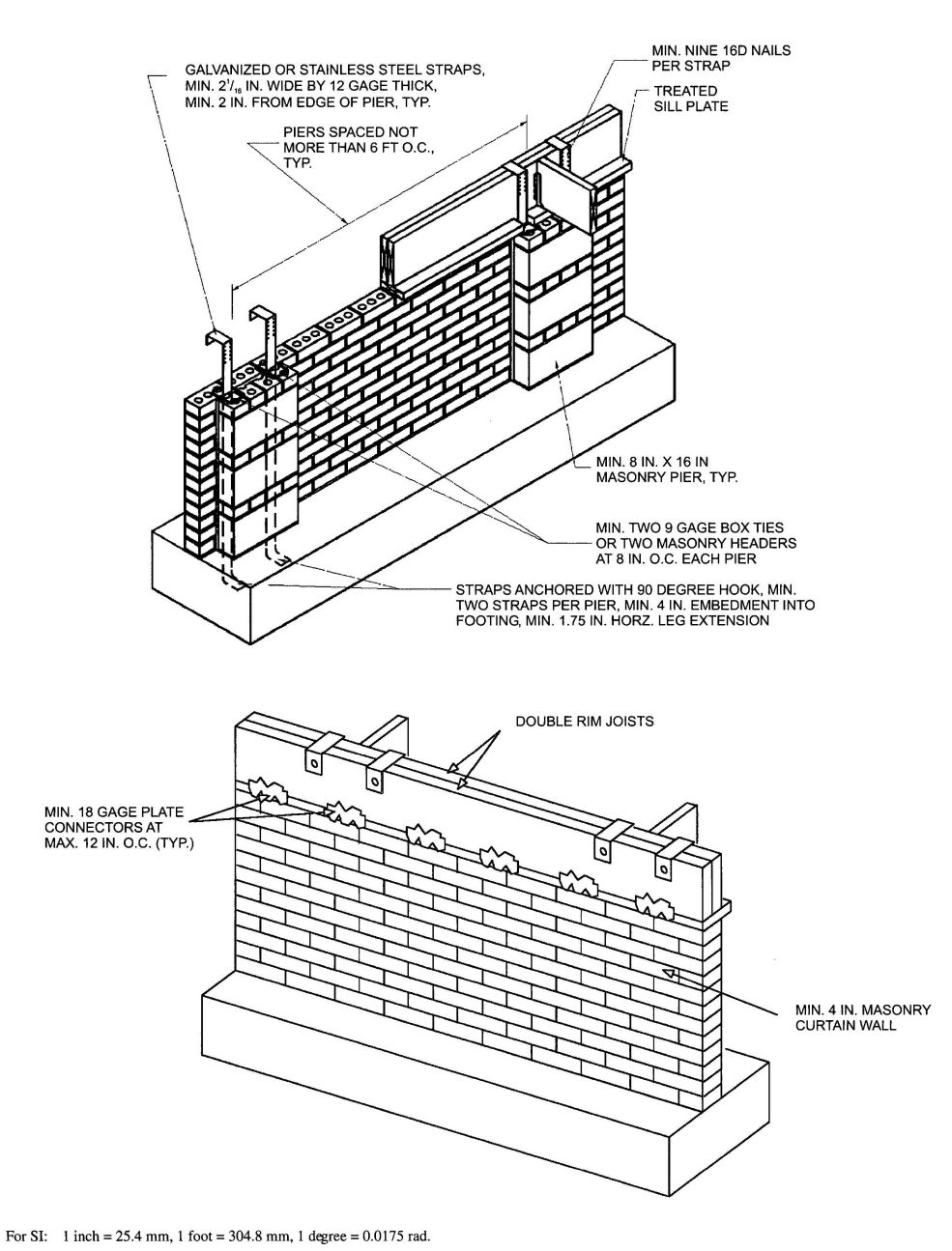
FIGURE R404.1.5(1)
FOUNDATION WALL CLAY MASONRY CURTAIN WALL WITH CONCRETE MASONRY PIERS
R404.1.6 Height above finished grade. Concrete and masonry foundation walls shall extend above the finished grade adjacent to the foundation at all points a minimum of 4 inches (102 mm) where masonry veneer is used and a minimum of 6 inches (152 mm) elsewhere.
R404.1.7 Backfill placement. Backfill shall not be placed against the wall until the wall has sufficient strength and has been anchored to the floor above, or has been sufficiently braced to prevent damage by the backfill.
Exception: Bracing is not required for walls supporting less than 4 feet (1219 mm) of unbalanced backfill.
R404.1.8 Rubble stone masonry. Rubble stone masonry foundation walls shall have a minimum thickness of 16 inches (406 mm), shall not support an unbalanced backfill exceeding 8 feet (2438 mm) in height, shall not support a soil pressure greater than 30 pounds per square foot per foot (4.71 kPa/m), and shall not be constructed in Seismic Design Categories D0, D1, D2 or townhouses in Seismic Design Category C, as established in Figure R301.2(2).
R404.2 Wood foundation walls. Wood foundation walls shall be constructed in accordance with the provisions of Sections R404.2.1 through R404.2.6 and with the details shown in Figures R403.1(2) and R403.1(3).
R404.2.1 Identification. All load-bearing lumber shall be identified by the grade mark of a lumber grading or inspection agency which has been approved by an accreditation body that complies with DOC PS 20. In lieu of a grade mark, a certificate of inspection issued by a lumber grading or inspection agency meeting the requirements of this section shall be accepted. Wood structural panels shall conform to DOC PS 1 or DOC PS 2 and shall be identified by a grade mark or certificate of inspection issued by an approved agency.
R404.2.2 Stud size. The studs used in foundation walls shall be 2-inch by 6-inch (51 mm by 152 mm) members. When spaced 16 inches (406 mm) on center, a wood species with an Fb value of not less than 1,250 pounds per square inch (8619 kPa) as listed in AF&PA/NDS shall be used. When spaced 12 inches (305 mm) on center, an Fb of not less than 875 psi (6033 kPa) shall be required.
R404.2.3 Height of backfill. For wood foundations that are not designed and installed in accordance with AF&PA PWF, the height of backfill against a foundation wall shall not exceed 4 feet (1219 mm). When the height of fill is more than 12 inches (305 mm) above the interior grade of a crawl space or floor of a basement, the thickness of the plywood sheathing shall meet the requirements of Table R404.2.3.
R404.2.4 Backfilling. Wood foundation walls shall not be backfilled until the basement floor and first floor have been constructed or the walls have been braced. For crawl space construction, backfill or bracing shall be installed on the interior of the walls prior to placing backfill on the exterior.
R404.2.5 Drainage and dampproofing. Wood foundation basements shall be drained and dampproofed in accordance with Sections R405 and R406, respectively.
R404.2.6 Fastening. Wood structural panel foundation wall sheathing shall be attached to framing in accordance with Table R602.3(1) and Section R402.1.1.
R404.3 Wood sill plates. Wood sill plates shall be a minimum of 2-inch by 4-inch (51 mm by 102 mm) nominal lumber. Sill plate anchorage shall be in accordance with Sections R403.1.6 and R602.11.
R404.4 Retaining walls. Retaining walls that are not laterally supported at the top and that retain in excess of 24 inches (610 mm) of unbalanced fill shall be designed to ensure stability against overturning, sliding, excessive foundation pressure and water uplift. Retaining walls shall be designed for a safety factor of 1.5 against lateral sliding and overturning.
404.5 Precast concrete foundation walls.
R404.5.1 Design. Precast concrete foundation walls shall be designed in accordance with accepted engineering practice. The design and manufacture of precast concrete foundation wall panels shall comply with the materials requirements of Section R402.3 or ACI 318. The panel design drawings shall be prepared by a registered design professional.
R404.5.2 Precast concrete foundation design drawings. Precast concrete foundation wall design drawings shall be submitted to the building official and approved prior to installation. Drawings shall include, at a minimum, the information specified below:
R404.5.3 Identification. Precast concrete foundation wall panels shall be identified by a certificate of inspection label issued by an approved third party inspection agency.
| HEIGHT OF FILL (inches) | STUD SPACING (inches) | FACE GRAIN ACROSS STUDS | FACE GRAIN PARALLEL TO STUDS | ||||
|---|---|---|---|---|---|---|---|
| Gradea | Minimum thickness (inches) | Span rating | Gradea | Minimum thickness (inches)b, c | Span rating | ||
| For SI: 1 inch = 25.4 mm, 1 foot = 304.8 mm, 1 pound per cubic foot = 0.1572kN/m3. | |||||||
| a. Plywood shall be of the following minimum grades in accordance with DOC PS 1 or DOC PS 2: | |||||||
| 1. DOC PS 1 Plywood grades marked: | |||||||
| 1.1. Structural I C-D (Exposure 1) | |||||||
| 1.2. C-D (Exposure 1) | |||||||
| 2. DOC PS 2 Plywood grades marked: | |||||||
| 2.1. Structural I Sheathing (Exposure 1) | |||||||
| 2.2. Sheathing (Exposure 1) | |||||||
| 3. Where a major portion of the wall is exposed above ground and a better appearance is desired, the following plywood grades marked exterior are suitable: | |||||||
| 3.1 Structural I A-C, Structural I B-C or Structural I C-C (Plugged) in accordance with DOC PS 1 | |||||||
| 3.2. A-C Group 1, B-C Group 1, C-C (Plugged) Group 1 or MDO Group 1 in accordance with DOC PS 1 | |||||||
| 3.3. Single Floor in accordance with DOC PS 1 or DOC PS 2 | |||||||
| b. Minimum thickness 15/32 inch, except crawl space sheathing may be 3/8 inch for face grain across studs 16 inches on center and maximum 2-foot depth of unequal fill. | |||||||
| c. For this fill height, thickness and grade combination, panels that are continuous over less than three spans (across less than three stud spacings) require blocking 16 inches above the bottom plate. Offset adjacent blocks and fasten through studs with two 16d corrosion-resistant nails at each end. | |||||||
| 24 | 12 | B | 15⁄32 | 32⁄16 | A | 15⁄32 | 32⁄16. |
| B | 15⁄32c | 32⁄16 | |||||
| 16 | B | 15⁄32 | 32⁄16 | A | 15⁄32c | 32⁄16 | |
| B | 19⁄32c(4, 5 ply) | 40⁄20 | |||||
| 36 | 12 | B | 15⁄32 | 32⁄16 | A | 15⁄32 | 32⁄16 |
| B | 15⁄32c (4, 5 ply) | 32⁄16 | |||||
| B | 19⁄32(4, 5 ply) | 40⁄20 | |||||
| 16 | B | 15⁄32c | 32⁄16 | A | 19⁄32 | 40⁄20 | |
| B | 23⁄32 | 48⁄24 | |||||
| 48 | 12 | B | 15⁄32 | 32⁄16 | A | 15⁄32c | 32⁄16 |
| B | 19⁄32c (4, 5 ply) | 40⁄20 | |||||
| 16 | B | 19⁄32 | 40⁄20 | A | 19⁄32c | 40⁄20 | |
| A | 23⁄32 | 48⁄24 | |||||
R405.1 Concrete or masonry foundations. Drains shall be provided around all concrete or masonry foundations that retain earth and enclose habitable or usable spaces located below grade. Drainage tiles, gravel or crushed stone drains, perforated pipe or other approved systems or materials shall be installed at or below the area to be protected and shall discharge by gravity or mechanical means into an approved drainage system. Gravel or crushed stone drains shall extend at least 1 foot (305 mm) beyond the outside edge of the footing and 6 inches (152 mm) above the top of the footing and be covered with an approved filter membrane material. The top of open joints of drain tiles shall be protected with strips of building paper, and the drainage tiles or perforated pipe shall be placed on a minimum of 2 inches (51 mm) of washed gravel or crushed rock at least one sieve size larger than the tile joint opening or perforation and covered with not less than 6 inches (152 mm) of the same material.
Exception: A drainage system is not required when the foundation is installed on well-drained ground or sand-gravel mixture soils according to the Unified Soil Classification System, Group I Soils, as detailed in Table R405.1.
R405.1.1 Precast concrete foundation. Precast concrete walls that retain earth and enclose habitable or useable space located below-grade that rest on crushed stone footings shall have a perforated drainage pipe installed below the base of the wall on either the interior or exterior side of the wall, at least one foot (305 mm) beyond the edge of the wall. If the exterior drainage pipe is used, an approved filter membrane material shall cover the pipe. The drainage system shall discharge into an approved sewer system or to daylight.
R405.2 Wood foundations. Wood foundations enclosing habitable or usable spaces located below grade shall be adequately drained in accordance with Sections R405.2.1 through R405.2.3.
R405.2.1 Base. A porous layer of gravel, crushed stone or coarse sand shall be placed to a minimum thickness of 4 inches (102 mm) under the basement floor. Provision shall be made for automatic draining of this layer and the gravel or crushed stone wall footings.
| SOIL GROUP | UNIFIED SOIL CLASSIFICATION SYSTEM SYMBOL | SOIL DESCRIPTION | DRAINAGE CHARACTERISTICSa | FROST HEAVE POTENTIAL | VOLUME CHANGE POTENTIAL EXPANSIONb |
|---|---|---|---|---|---|
| For SI: 1 inch = 25.4 mm. | |||||
| a. The percolation rate for good drainage is over 4 inches per hour, medium drainage is 2 inches to 4 inches per hour, and poor is less than 2 inches per hour. | |||||
| b. Soils with a low potential expansion typically have a plasticity index (PI) of 0 to 15, soils with a medium potential expansion have a PI of 10 to 35 and soils with a high potential expansion have a PI greater than 20. | |||||
| Group I | GW | Well-graded gravels, gravel sand mixtures, little or no fines | Good | Low | Low |
| GP | Poorly graded gravels or gravel sand mixtures, little or no fines | Good | Low | Low | |
| SW | Well-graded sands, gravelly sands, little or no fines | Good | Low | Low | |
| SP | Poorly graded sands or gravelly sands, little or no fines | Good | Low | Low | |
| GM | Silty gravels, gravel-sand-silt mixtures | Good | Medium | Low | |
| SM | Silty sand, sand-silt mixtures | Good | Medium | Low | |
| Group II | GC | Clayey gravels, gravel-sand-clay mixtures | Medium | Medium | Low |
| SC | Clayey sands, sand-clay mixture | Medium | Medium | Low | |
| ML | Inorganic silts and very fine sands, rock flour, silty or clayey fine sands or clayey silts with slight plasticity | Medium | High | Low | |
| CL | Inorganic clays of low to medium plasticity, gravelly clays, sandy clays, silty clays, lean clays | Medium | Medium | Medium to Low | |
| Group III | CH | Inorganic clays of high plasticity, fat clays | Poor | Medium | High |
| MH | Inorganic silts, micaceous or diatomaceous fine sandy or silty soils, elastic silts | Poor | High | High | |
| Group IV | OL | Organic silts and organic silty clays of low plasticity | Poor | Medium | Medium |
| OH | Organic clays of medium to high plasticity, organic silts | Unsatisfactory | Medium | High | |
| Pt | Peat and other highly organic soils | Unsatisfactory | Medium | High | |
R405.2.2 Vapor retarder. A 6-mil-thick (0.15 mm) polyethylene vapor retarder shall be applied over the porous layer with the basement floor constructed over the polyethylene.
R405.2.3 Drainage system. In other than Group I soils, a sump shall be provided to drain the porous layer and footings. The sump shall be at least 24 inches (610 mm) in diameter or 20 inches square (0.0129 m2), shall extend at least 24 inches (610 mm) below the bottom of the basement floor and shall be capable of positive gravity or mechanical drainage to remove any accumulated water. The drainage system shall discharge into an approved sewer system or to daylight.
R406.1 Concrete and masonry foundation dampproofing.Except where required by Section R406.2 to be waterproofed, foundation walls that retain earth and enclose interior spaces and floors below grade shall be dampproofed from the top of the footing to the finished grade. Masonry walls shall have not less than 3/8 inch (9.5 mm) portland cement parging applied to the exterior of the wall. The parging shall be dampproofed in accordance with one of the following:
Exception: Parging of unit masonry walls is not required where a material is approved for direct application to the masonry.
Concrete walls shall be dampproofed by applying any one of the above listed dampproofing materials or any one of the waterproofing materials listed in Section R406.2 to the exterior of the wall.
R406.2 Concrete and masonry foundation waterproofing. In areas where a high water table or other severe soil-water conditions are known to exist, exterior foundation walls that retain earth and enclose interior spaces and floors below grade shall be waterproofed from the top of the footing to the finished grade. Walls shall be waterproofed in accordance with one of the following:
Exception: Organic-solvent-based products such as hydrocarbons, chlorinated hydrocarbons, ketones and esters shall not be used for ICF walls with expanded polystyrene form material. Use of plastic roofing cements, acrylic coatings, latex coatings, mortars and pargings to seal ICF walls is permitted. Cold-setting asphalt or hot asphalt shall conform to type C of ASTM D 449. Hot asphalt shall be applied at a temperature of less than 200°F (93°C).
All joints in membrane waterproofing shall be lapped and sealed with an adhesive compatible with the membrane.
R406.3 Dampproofing for wood foundations. Wood foundations enclosing habitable or usable spaces located below grade shall be dampproofed in accordance with Sections R406.3.1 through R406.3.4.
R406.3.1 Panel joint sealed. Plywood panel joints in the foundation walls shall be sealed full length with a caulking compound capable of producing a moisture-proof seal under the conditions of temperature and moisture content at which it will be applied and used.
R406.3.2 Below-grade moisture barrier. A 6-mil-thick (0.15 mm) polyethylene film shall be applied over the below-grade portion of exterior foundation walls prior to backfilling. Joints in the polyethylene film shall be lapped 6 inches (152 mm) and sealed with adhesive. The top edge of the polyethylene film shall be bonded to the sheathing to form a seal. Film areas at grade level shall be protected from mechanical damage and exposure by a pressure preservatively treated lumber or plywood strip attached to the wall several inches above finish grade level and extending approximately 9 inches (229 mm) below grade. The joint between the strip and the wall shall be caulked full length prior to fastening the strip to the wall. Other coverings appropriate to the architectural treatment may also be used. The polyethylene film shall extend down to the bottom of the wood footing plate but shall not overlap or extend into the gravel or crushed stone footing.
R406.3.3 Porous fill. The space between the excavation and the foundation wall shall be backfilled with the same material used for footings, up to a height of 1 foot (305 mm) above the footing for well-drained sites, or one-half the total back-fill height for poorly drained sites. The porous fill shall be covered with strips of 30-pound (13.6 kg) asphalt paper or 6-mil (0.15 mm) polyethylene to permit water seepage while avoiding infiltration of fine soils.
R406.3.4 Backfill. The remainder of the excavated area shall be backfilled with the same type of soil as was removed during the excavation.
R406.4 Precast concrete foundation system dampproofing. Except where required by Section R406.2 to be waterproofed, precast concrete foundation walls enclosing habitable or useable spaces located below grade shall be dampproofed in accordance with Section R406.1.
157R406.4.1 Panel joints sealed. Precast concrete foundation panel joints shall be sealed full height with a sealant meeting ASTM C 920, Type S or M, Grade NS, Class 25, Use NT, M or A. Joint sealant shall be installed in accordance with the manufacturer's installation instructions.
R407.1 Wood column protection. Wood columns shall be protected against decay as set forth in Section R317.
R407.2 Steel column protection. All surfaces (inside and outside) of steel columns shall be given a shop coat of rust-inhibitive paint, except for corrosion-resistant steel and steel treated with coatings to provide corrosion resistance.
R407.3 Structural requirements. The columns shall be restrained to prevent lateral displacement at the bottom end. Wood columns shall not be less in nominal size than 4 inches by 4 inches (102 mm by 102 mm). Steel columns shall not be less than 3-inch-diameter (76 mm) Schedule 40 pipe manufactured in accordance with ASTM A 53 Grade B or approved equivalent.
Exception: In Seismic Design Categories A, B and C, columns no more than 48 inches (1219 mm) in height on a pier or footing are exempt from the bottom end lateral displacement requirement within under-floor areas enclosed by a continuous foundation.
R408.1 Ventilation. The under-floor space between the bottom of the floor joists and the earth under any building (except space occupied by a basement) shall have ventilation openings through foundation walls or exterior walls. The minimum net area of ventilation openings shall not be less than 1 square foot (0.0929 m2) for each 150 square feet (14 m2) of under-floor space area, unless the ground surface is covered by a Class 1 vapor retarder material. When a Class 1 vapor retarder material is used, the minimum net area of ventilation openings shall not be less than 1 square foot (0.0929 m2) for each 1,500 square feet (140 m2) of under-floor space area. One such ventilating opening shall be within 3 feet (914 mm) of each corner of the building.
R408.2 Openings for under-floor ventilation. The minimum net area of ventilation openings shall not be less than 1 square foot (0.0929 m2) for each 150 square feet (14 m2) of under-floor area. One ventilation opening shall be within 3 feet (915 mm) of each corner of the building. Ventilation openings shall be covered for their height and width with any of the following materials provided that the least dimension of the covering shall not exceed ¼ inch (6.4 mm):
Exception: The total area of ventilation openings shall be permitted to be reduced to 1&7frac1500; of the under-floor area where the ground surface is covered with an approved Class I vapor retarder material and the required openings are placed to provide cross ventilation of the space . The instalation of operable louvers shall not be prohibited.
R408.3 Unvented crawl space. Ventilation openings in under-floor spaces specified in Sections R408.1 and R408.2 shall not be required where:
R408.4 Access. Access shall be provided to all under-floor spaces. Access openings through the floor shall be a minimum of 18 inches by 24 inches (457 mm by 610 mm). Openings through a perimeter wall shall be not less than 16 inches by 24 inches (407 mm by 610 mm). When any portion of the through-wall access is below grade, an areaway not less than 16 inches by 24 inches (407 mm by 610 mm) shall be provided. The bottom of the areaway shall be below the threshold of the access opening. Through wall access openings shall not be located under a door to the residence. See the California Mechanical Code for access requirements where mechanical equipment is located under floors.
R408.5 Removal of debris. The under-floor grade shall be cleaned of all vegetation and organic material. All wood forms used for placing concrete shall be removed before a building is occupied or used for any purpose. All construction materials shall be removed before a building is occupied or used for any purpose.
R408.6 Finished grade. The finished grade of under-floor surface may be located at the bottom of the footings; however, where there is evidence that the groundwater table can rise to within 6 inches (152 mm) of the finished floor at the building perimeter or where there is evidence that the surface water does not readily drain from the building site, the grade in the under-floor space shall be as high as the outside finished grade, unless an approved drainage system is provided.
R408.7 Flood resistance. For buildings located in areas prone to flooding as established in Table R301.2(1):
159 160Exception: Under-floor spaces that meet the requirements of FEMA/FIA TB 11-1.
| Adopting agency | BSC | SFM | HCD | DSA | OSHPD | CSA | DPH | AGR | DWR | CEC | CA | SL | SLC | ||||||
|---|---|---|---|---|---|---|---|---|---|---|---|---|---|---|---|---|---|---|---|
| 1 | 2 | 1-AC | AC | SS | 1 | 2 | 3 | 4 | |||||||||||
| Adopt entire chapter | |||||||||||||||||||
| Adopt entire chapter as amended (amended sections listed below) |
X | X | |||||||||||||||||
| Adopt only those sections that are listed below |
|||||||||||||||||||
| Chapter/Section | |||||||||||||||||||
| R502.1 | X | X | |||||||||||||||||
| R502.11.1 | X | X | |||||||||||||||||
R501.1 Application. The provisions of this chapter shall control the design and construction of the floors for all buildings including the floors of attic spaces used to house mechanical or plumbing fixtures and equipment.
R501.2 Requirements. Floor construction shall be capable of accommodating all loads according to Section R301 and of transmitting the resulting loads to the supporting structural elements.
R502.1 Identification. Load-bearing dimension lumber for joists, beams and girders shall be identified by a grade mark of a lumber grading or inspection agency that has been approved by an accreditation body that complies with DOC PS 20. In lieu of a grade mark, a certificate of inspection issued by a lumber grading or inspection agency meeting the requirements of this section shall be accepted.
Note: See Section R301.1.1.1 for limited-density owner-built rural dwellings.
R502.1.1 Preservative-treated lumber. Preservative treated dimension lumber shall also be identified as required by Section R319.1.
R502.1.2 Blocking and subflooring. Blocking shall be a minimum of utility grade lumber. Subflooring may be a minimum of utility grade lumber or No. 4 common grade boards.
R502.1.3 End-jointed lumber. Approved end-jointed lumber identified by a grade mark conforming to Section R502.1 may be used interchangeably with solid-sawn members of the same species and grade.
R502.1.4 Prefabricated wood I-joists. Structural capacities and design provisions for prefabricated wood I-joists shall be established and monitored in accordance with ASTM D 5055.
R502.1.5 Structural glued laminated timbers. Glued laminated timbers shall be manufactured and identified as required in ANSI/AITC A 190.1 and ASTM D 3737.
R502.1.6 Structural log members. Stress grading of structural log members of nonrectangular shape, as typically used in log buildings, shall be in accordance with ASTM D 3957. Such structural log members shall be identified by the grade mark of an approved lumber grading or inspection agency. In lieu of a grade mark on the material, a certificate of inspection as to species and grade issued by a lumber-grading or inspection agency meeting the requirements of this section shall be permitted to be accepted.
R502.1.7 Exterior wood/plastic composite deck boards. Wood/plastic composites used in exterior deck boards shall comply with the provisions of Section R317.4.
R502.2 Design and construction. Floors shall be designed and constructed in accordance with the provisions of this chapter, Figure R502.2 and Sections R317 and R318 or in accordance with AF&PA/NDS.
R502.2.1 Framing at braced wall lines. A load path for lateral forces shall be provided between floor framing and braced wall panels located above or below a floor, as specified in Section R602.10.6.
R502.2.2 Decks. Where supported by attachment to an exterior wall, decks shall be positively anchored to the primary structure and designed for both vertical and lateral loads as applicable. Such attachment shall not be accomplished by the use of toenails or nails subject to withdrawal. Where positive connection to the primary building structure cannot be verified during inspection, decks shall be self-supporting. For decks with cantilevered framing members, connections to exterior walls or other framing members, shall be designed and constructed to resist uplift resulting from the full live load specified in Table R301.5 acting on the cantilevered portion of the deck.
R502.2.2.1 Deck ledger connection to band joist. For decks supporting a total design load of 50 pounds per square foot (2394 Pa) [40 pounds per square foot (1915 Pa) live load plus 10 pounds per square foot (479 Pa) dead load], the connection between a deck ledger of pressure-preservative-treated Southern Pine, incised pressure-preservative-treated Hem-Fir or approved decay-resistant species, and a 2-inch (51 mm) nominal lumber band joist bearing on a sill plate or wall plate shall be constructed with ½-inch (12.7 m) lag screws or bolts with washers in accordance with Table R502.2.2.1. Lag screws, bolts and washers shall be hot-dipped galvanized or stainless steel.
R502.2.2.1.1 Placement of lag screws or bolts in deck ledgers. The lag screws or bolts shall be placed 2 inches (51 mm) in from the bottom or top of the deck ledgers and between 2 and 5 inches (51 and 127 mm) in from the ends. The lag screws or bolts shall be staggered from the top to the bottom along the horizontal run of the deck ledger.
R502.2.2.2 Alternate deck ledger connections. Deck ledger connections not conforming to Table R502.2.2.1 shall be designed in accordance with accepted engineering practice. Girders supporting deck joists shall not be supported on deck ledgers or band joists. Deck ledgers shall not be supported on stone or masonry veneer.
R502.2.2.3 Deck lateral load connection. The lateral load connection required by Section R502.2.2 shall be permitted to be in accordance with Figure R502.2.2.3. Hold-down tension devices shall be installed in not less than two locations per deck, and each device shall have an allowable stress design capacity of not less than 1500 pounds (6672 N).
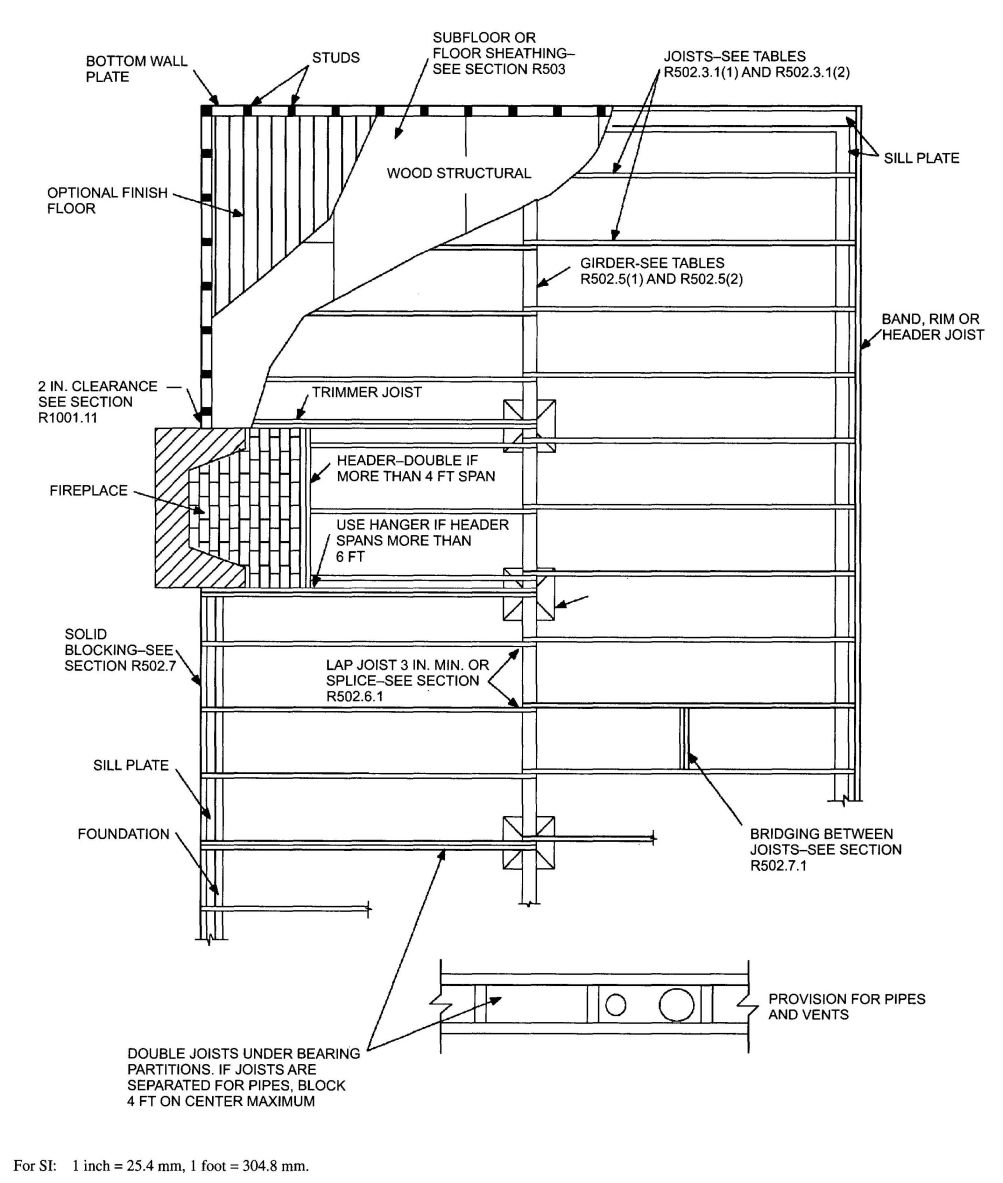
FIGURE R502.2
FLOOR CONSTRUCTION
| JOIST SPAN | 6″ and less | 6″1″ to 8″ | 8″1″ to 10″ | 10″1″ to 12″ | 12″1″ to 14″ | 14″1″ to 16″ | 16″1″ to 18″ |
|---|---|---|---|---|---|---|---|
| Connection details | On-center spacing of fastenersd, e | ||||||
| For SI: 1 inch = 25.4 mm, 1 foot = 304.8 mm. 1 pound per square foot = 0.0479kPa. | |||||||
| a. The tip of the lag screw shall fully extend beyond the inside face of the band joist. | |||||||
| b. The maximum gap between the face of the ledger board and face of the wall sheathing shall be ½″. | |||||||
| c. Ledgers shall be flashed to prevent water from contacting the house band joist. | |||||||
| d. Lag screws and bolts shall be staggered in accordance with Section R502.2.2.1.1. | |||||||
| e. Deck ledger shall be minimum 2×8 pressure-preservative-treated No. 2 grade lumber, or other approved materials as established by standard engineering practice. | |||||||
| f. When solid-sawn pressure-preservative-treated deck ledgers are attached to a minimum 1 inch thick engineered wood product (structural composite lumber, laminated veneer lumber or wood structural panel band joist), the ledger attachment shall be designed in accordance with accepted engineering practice. | |||||||
| g. A minimum 1×9½ Douglas Fir laminated veneer lumber rimboard shall be permitted in lieu of the 2-inch nominal band joist. | |||||||
| h. Wood structural panel sheathing, gypsum board sheathing or foam sheathing not exceeding 1 inch in thickness shall be permitted. The maximum distance between the face of the ledger board and the face of the band joist shall be 1 inch. | |||||||
| ½ inch diameter lag screw with 15/32 inch maximum sheathinga | 30 | 23 | 18 | 15 | 13 | 11 | 10 |
| ½ inch diameter bolt with 15/32 inch maximum sheathing | 36 | 36 | 34 | 29 | 24 | 21 | 19 |
| ½ inch diameter bolt with 15/32 inch maximum sheathing and ½ inch stacked washersb, h | 36 | 36 | 29 | 24 | 21 | 18 | 16 |
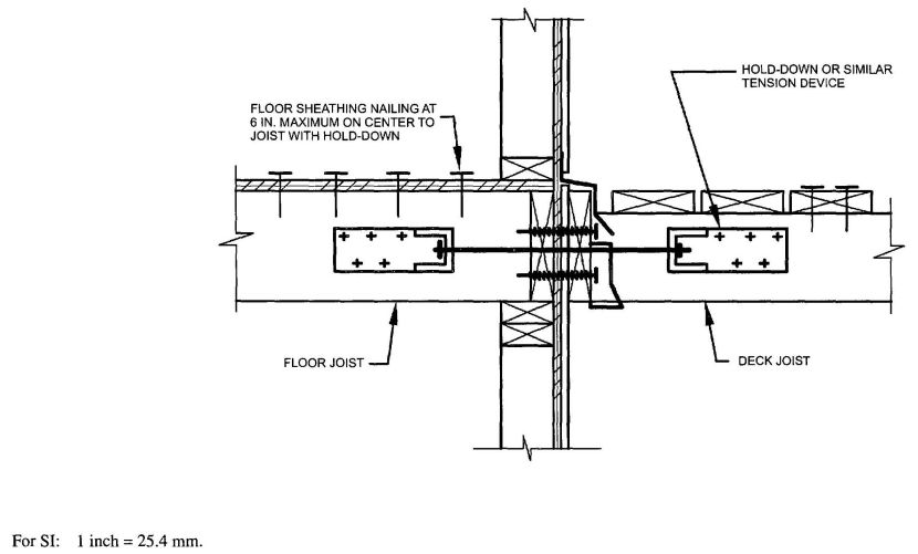
FIGURE 502.2.2.3
DECK ATTACHMENT FOR LATERAL LOADS
R502.2.2.4 Exterior wood/plastic composite deck boards. Wood/plastic composite deck boards shall be installed in accordance with the manufacturer's instructions.
R502.3 Allowable joist spans. Spans for floor joists shall be in accordance with Tables R502.3.1(1) and R502.3.1(2). For other grades and species and for other loading conditions, refer to the AF&PA Span Tables for Joists and Rafters.
R502.3.1 Sleeping areas and attic joists. Table R502.3.1(1) shall be used to determine the maximum allowable span of floor joists that support sleeping areas and attics that are accessed by means of a fixed stairway in accordance with Section R311.7 provided that the design live load does not exceed 30 pounds per square foot (1.44 kPa) and the design dead load does not exceed 20 pounds per square foot (0.96 kPa). The allowable span of ceiling joists that support attics used for limited storage or no storage shall be determined in accordance with Section R802.4.
R502.3.2 Other floor joists. Table R502.3.1(2) shall be used to determine the maximum allowable span of floor joists that support all other areas of the building, other than sleeping rooms and attics, provided that the design live load does not exceed 40 pounds per square foot (1.92 kPa) and the design dead load does not exceed 20 pounds per square foot (0.96 kPa).
R502.3.3 Floor cantilevers. Floor cantilever spans shall not exceed the nominal depth of the wood floor joist. Floor cantilevers constructed in accordance with Table R502.3.3(1) shall be permitted when supporting a light-frame bearing wall and roof only. Floor cantilevers supporting an exterior balcony are permitted to be constructed in accordance with Table R502.3.3(2).
R502.4 Joists under bearing partitions. Joists under parallel bearing partitions shall be of adequate size to support the load. Double joists, sized to adequately support the load, that are separated to permit the installation of piping or vents shall be full depth solid blocked with lumber not less than 2 inches (51 mm) in nominal thickness spaced not more than 4 feet (1219 mm) on center. Bearing partitions perpendicular to joists shall not be offset from supporting girders, walls or partitions more than the joist depth unless such joists are of sufficient size to carry the additional load.
R502.5 Allowable girder spans. The allowable spans of girders fabricated of dimension lumber shall not exceed the values set forth in Tables R502.5(1) and R502.5(2).
R502.6 Bearing. The ends of each joist, beam or girder shall have not less than 1.5 inches (38 mm) of bearing on wood or metal and not less than 3 inches (76 mm) on masonry or concrete except where supported on a 1-inch-by-4-inch (25.4 mm by 102 mm) ribbon strip and nailed to the adjacent stud or by the use of approvedjoist hangers.
R502.6.1 Floor systems. Joists framing from opposite sides over a bearing support shall lap a minimum of 3 inches (76 mm) and shall be nailed together with a minimum three 10d face nails. A wood or metal splice with strength equal to or greater than that provided by the nailed lap is permitted.
R502.6.2 Joist framing. Joists framing into the side of a wood girder shall be supported by approved framing anchors or on ledger strips not less than nominal 2 inches by 2 inches (51 mm by 51 mm).
R502.7 Lateral restraint at supports. Joists shall be supported laterally at the ends by full-depth solid blocking not less than 2 inches (51 mm) nominal in thickness; or by attachment to a full-depth header, band or rim joist, or to an adjoining stud or shall be otherwise provided with lateral support to prevent rotation.
Exceptions:
- Trusses, structural composite lumber, structural glued-laminated members and I-joists shall be supported laterally as required by the manufacturer's recommendations.
- In Seismic Design Categories D0, D1 and D2, lateral restraint shall also be provided at each intermediate support.
R502.7.1 Bridging. Joists exceeding a nominal 2 inches by 12 inches (51 mm by 305 mm) shall be supported laterally by solid blocking, diagonal bridging (wood or metal), or a continuous 1-inch-by-3-inch (25.4 mm by 76 mm) strip nailed across the bottom of joists perpendicular to joists at intervals not exceeding 8 feet (2438 mm).
Exception: Trusses, structural composite lumber, structural glued-laminated members and I-joists shall be supported laterally as required by the manufacturer's recommendations.
R502.8 Drilling and notching. Structural floor members shall not be cut, bored or notched in excess of the limitations specified in this section. See Figure R502.8.
R502.8.1 Sawn lumber. Notches in solid lumber joists, refers and beams shall not exceed one-sixth of the depth of the member, shall not be longer than one-third of the depth of the member and shall not be located in the middle one-third of the span. Notches at the ends of the member shall not exceed one-fourth the depth of the member. The tension side of members 4 inches (102 mm) or greater in nominal thickness shall not be notches except at the ends of the members. The diameter of holes bored or cut into members shall not exceed one-third the depth of the member. Holes shall not be closer than 2 inches (51 mm) to the top or bottom of the member, or to any other hole located in the member. Where the member is also notched, the hole shall not be closer than 2 inches (51 mm) to the notch.
R502.8.2 Engineered wood products. Cuts, notches and holes bored in trusses, structural composite lumber, structural glue-laminated members or I-joists are prohibited except where permitted by the manufacture's recommendations or where the effects of such alterations are specifically considered in the design of the member by a registered design professional.
R502.9 Fastening. Floor framing shall be nailed in accordance with Table R602.3(1). Where posts and beam or girder construction is used to support floor framing, positive connections shall be provided to ensure against uplift and lateral displacement.
| JOIST SPACING (inches) | SPECIES AND GRADE | DEAD LOAD = 10 psf | DEAD LOAD = 20 psf | |||||||
|---|---|---|---|---|---|---|---|---|---|---|
| 2×6 | 2×8 | 2×10 | 2×12 | 2×6 | 2×8 | 2×10 | 2×12 | |||
| Maximum floor joist spans | ||||||||||
| (ft - in.) | (ft - in.) | (ft - in.) | (ft - in.) | (ft - in.) | (ft - in.) | (ft - in.) | (ft - in.) | |||
| For SI: 1 inch = 25.4 mm, 1 foot = 304.8 mm, 1 pound per square foot = 0.0479 kPa. | ||||||||||
| Note: Check sources for availability of lumber in lengths greater than 20 feet. | ||||||||||
| a. Dead load limits for townhouses in Seismic Design Category C and all structures in Seismic Design Categories D0,D1 and D2 shall be determined in accordance with Section R301.2.2.2.1. | ||||||||||
| 12 | Douglas fir-larch | SS | 12-6 | 16-6 | 21-0 | 25-7 | 12-6 | 16-6 | 21-0 | 25-7 |
| Douglas fir-larch | #1 | 12-0 | 15-10 | 20-3 | 24-8 | 12-0 | 15-7 | 19-0 | 22-0 | |
| Douglas fir-larch | #2 | 11-10 | 15-7 | 19-10 | 23-0 | 11-6 | 14-7 | 17-9 | 20-7 | |
| Douglas fir-larch | #3 | 9-8 | 12-4 | 15-0 | 17-5 | 8-8 | 11-0 | 13-5 | 15-7 | |
| Hem-fir | SS | 11-10 | 15-7 | 19-10 | 24-2 | 11-10 | 15-7 | 19-10 | 24-2 | |
| Hem-fir | #1 | 11-7 | 15-3 | 19-5 | 23-7 | 11-7 | 15-2 | 18-6 | 21-6 | |
| Hem-fir | #2 | 11-10 | 14-6 | 18-6 | 22-6 | 11-0 | 14-4 | 17-6 | 20-4 | |
| Hem-fir | #3 | 9-8 | 12-4 | 15-0 | 17-5 | 8-8 | 11-0 | 13-5 | 15-7 | |
| Southern pine | SS | 12-3 | 16-2 | 20-8 | 25-1 | 12-3 | 16-2 | 20-8 | 25-1 | |
| Southern pine | #1 | 12-0 | 15-10 | 20-3 | 24-8 | 12-0 | 15-10 | 20-3 | 24-8 | |
| Southern pine | #2 | 11-10 | 15-7 | 19-10 | 24-2 | 11-10 | 15-7 | 18-7 | 21-9 | |
| Southern pine | #3 | 10-5 | 13-3 | 15-8 | 18-8 | 9-4 | 11-11 | 14-0 | 16-8 | |
| Spruce-pine-fir | SS | 11-7 | 15-3 | 19-5 | 23-7 | 11-7 | 15-3 | 19-5 | 23-7 | |
| Spruce-pine-fir | #1 | 11-3 | 14-11 | 19-0 | 23-0 | 11-3 | 14-7 | 17-9 | 20-7 | |
| Spruce-pine-fir | #2 | 11-3 | 14-11 | 19-0 | 23-0 | 11-3 | 14-7 | 17-9 | 20-7 | |
| Spruce-pine-fir | #3 | 9-8 | 12-4 | 15-0 | 17-5 | 8-8 | 11-0 | 13-5 | 15-7 | |
| 16 | Douglas fir-larch | SS | 11-4 | 15-0 | 19-1 | 23-3 | 11-4 | 15-0 | 19-1 | 23-0 |
| Douglas fir-larch | #1 | 10-11 | 14-5 | 18-5 | 21-4 | 10-8 | 13-6 | 16-5 | 19-1 | |
| Douglas fir-larch | #2 | 10-9 | 14-1 | 17-2 | 19-11 | 9-11 | 12-7 | 15-5 | 17-10 | |
| Douglas fir-larch | #3 | 8-5 | 10-8 | 13-0 | 15-1 | 7-6 | 9-6 | 11-8 | 13-6 | |
| Hem-fir | SS | 10-9 | 14-2 | 18-0 | 21-11 | 10-9 | 14-2 | 18-0 | 21-11 | |
| Hem-fir | #1 | 10-6 | 13-10 | 17-8 | 20-9 | 10-4 | 13-1 | 16-0 | 18-7 | |
| Hem-fir | #2 | 10-0 | 13-2 | 16-10 | 19-8 | 9-10 | 12-5 | 15-2 | 17-7 | |
| Hem-fir | #3 | 8-5 | 10-8 | 13-0 | 15-1 | 7-6 | 9-6 | 11-8 | 13-6 | |
| Southern pine | SS | 11-2 | 14-8 | 18-9 | 22-10 | 11-2 | 14-8 | 18-9 | 22-10 | |
| Southern pine | #1 | 10-11 | 14-5 | 18-5 | 22-5 | 10-11 | 14-5 | 17-11 | 21-4 | |
| Southern pine | #2 | 10-9 | 14-2 | 18-0 | 21-1 | 10-5 | 13-6 | 16-1 | 18-10 | |
| Southern pine | #3 | 9-0 | 11-6 | 13-7 | 16-2 | 8-1 | 10-3 | 12-2 | 14-6 | |
| Spruce-pine-fir | SS | 10-6 | 13-10 | 17-8 | 21-6 | 10-6 | 13-10 | 17-8 | 21-4 | |
| Spruce-pine-fir | #1 | 10-3 | 13-6 | 17-2 | 19-11 | 9-11 | 12-7 | 15-5 | 17-10 | |
| Spruce-pine-fir | #2 | 10-3 | 13-6 | 17-2 | 19-11 | 9-11 | 12-7 | 15-5 | 17-10 | |
| Spruce-pine-fir | #3 | 8-5 | 10-8 | 13-0 | 15-1 | 7-6 | 9-6 | 11-8 | 13-6 | |
| 19.2 | Douglas fir-larch | SS | 10-8 | 14-1 | 18-0 | 21-10 | 10-8 | 14-1 | 18-0 | 21-0 |
| Douglas fir-larch | #1 | 10-4 | 13-7 | 16-9 | 19-6 | 9-8 | 12-4 | 15-0 | 17-5 | |
| Douglas fir-larch | #2 | 10-1 | 12-10 | 15-8 | 18-3 | 9-1 | 11-6 | 14-1 | 16-3 | |
| Douglas fir-larch | #3 | 7-8 | 9-9 | 11-10 | 13-9 | 6-10 | 8-8 | 10-7 | 12-4 | |
| Hem-fir | SS | 10-1 | 13-4 | 17-0 | 20-8 | 10-1 | 13-4 | 17-0 | 20-7 | |
| Hem-fir | #1 | 9-10 | 13-0 | 16-4 | 19-0 | 9-6 | 12-0 | 14-8 | 17-0 | |
| Hem-fir | #2 | 9-5 | 12-5 | 15-6 | 17-1 | 8-11 | 11-4 | 13-10 | 16-1 | |
| Hem-fir | #3 | 7-8 | 9-9 | 11-10 | 13-9 | 6-10 | 8-8 | 10-7 | 12-4 | |
| Southern pine | SS | 10-6 | 13-10 | 17-8 | 21-6 | 10-6 | 13-10 | 17-8 | 21-6 | |
| Southern pine | #1 | 10-4 | 13-7 | 17-4 | 21-1 | 10-4 | 13-7 | 16-4 | 19-6 | |
| Southern pine | #2 | 10-1 | 13-4 | 16-5 | 19-3 | 9-6 | 12-4 | 14-8 | 17-2 | |
| Southern pine | #3 | 8-3 | 10-6 | 12-5 | 14-9 | 7-4 | 9-5 | 11-1 | 13-2 | |
| Spruce-pine-fir | SS | 9-10 | 13-0 | 16-7 | 20-2 | 9-10 | 13-0 | 16-7 | 19-6 | |
| Spruce-pine-fir | #1 | 9-8 | 12-9 | 15-8 | 18-3 | 9-1 | 11-6 | 14-1 | 16-3 | |
| Spruce-pine-fir | #2 | 9-8 | 12-9 | 15-8 | 18-3 | 9-1 | 11-6 | 14-1 | 16-3 | |
| Spruce-pine-fir | #3 | 7-8 | 9-9 | 11-10 | 13-9 | 6-10 | 8-8 | 10-7 | 12-4 | |
| 24 | Douglas fir-larch | SS | 9-11 | 13-1 | 16-8 | 20-3 | 9-11 | 13-1 | 16-2 | 18-9 |
| Douglas fir-larch | #1 | 9-7 | 12-4 | 15-0 | 17-5 | 8-8 | 11-0 | 13-5 | 15-7 | |
| Douglas fir-larch | #2 | 9-1 | 11-6 | 14-1 | 16-3 | 8-1 | 10-3 | 12-7 | 14-7 | |
| Douglas fir-larch | #3 | 6-10 | 8-8 | 10-7 | 12-4 | 6-2 | 7-9 | 9-6 | 11-0 | |
| Hem-fir | SS | 9-4 | 12-4 | 15-9 | 19-2 | 9-4 | 12-4 | 15-9 | 18-5 | |
| Hem-fir | #1 | 9-2 | 12-0 | 14-8 | 17-0 | 8-6 | 10-9 | 13-1 | 15-2 | |
| Hem-fir | #2 | 8-9 | 11-4 | 13-10 | 16-1 | 8-0 | 10-2 | 12-5 | 14-4 | |
| Hem-fir | #3 | 6-10 | 8-8 | 10-7 | 12-4 | 6-2 | 7-9 | 9-6 | 11-0 | |
| Southern pine | SS | 9-9 | 12-10 | 16-5 | 19-11 | 9-9 | 12-10 | 16-5 | 19-11 | |
| Southern pine | #1 | 9-7 | 12-7 | 16-1 | 19-6 | 9-7 | 12-4 | 14-7 | 17-5 | |
| Southern pine | #2 | 9-4 | 12-4 | 14-8 | 17-2 | 8-6 | 11-0 | 13-1 | 15-5 | |
| Southern pine | #3 | 7-4 | 9-5 | 11-1 | 13-2 | 6-7 | 8-5 | 9-11 | 11-10 | |
| Spruce-pine-fir | SS | 9-2 | 12-1 | 15-5 | 18-9 | 9-2 | 12-1 | 15-0 | 17-5 | |
| Spruce-pine-fir | #1 | 8-11 | 11-6 | 14-1 | 16-3 | 8-1 | 10-3 | 12-7 | 14-7 | |
| Spruce-pine-fir | #2 | 8-11 | 11-6 | 14-1 | 16-3 | 8-1 | 10-3 | 12-7 | 14-7 | |
| Spruce-pine-fir | #3 | 6-10 | 8-8 | 10-7 | 12-4 | 6-2 | 7-9 | 9-6 | 11-0 | |
| JOIST SPACING (inches) | SPECIES AND GRADE | DEAD LOAD = 10 psf | DEAD LOAD = 20 psf | |||||||
|---|---|---|---|---|---|---|---|---|---|---|
| 2×6 | 2×8 | 2×10 | 2×12 | 2×6 | 2×8 | 2×10 | 2×12 | |||
| Maximum floor joist spans | ||||||||||
| (ft - in.) | (ft - in.) | (ft -in.) | (ft - in.) | (ft - in.) | (ft - in.) | (ft - in.) | (ft - in.) | |||
| For SI: 1 inch = 25.4 mm, 1 foot = 304.8 mm, 1 pound per square foot = 0.0479 kPa. | ||||||||||
| Note: Check sources for availability of lumber in lengths greater than 20 feet. | ||||||||||
| a. End bearing length shall be increased to 2 inches. | ||||||||||
| b. Dead load limits for townhouses in Seismic Design Category C and all structures in Seismic Design Categories D0, D1, and D2 shall be determined in accordance with Section R301.2.2.2.1. | ||||||||||
| 12 | Douglas fir-larch | SS | 11-4 | 15-0 | 19-1 | 23-3 | 11-4 | 15-0 | 19-1 | 23-3 |
| Douglas fir-larch | #1 | 10-11 | 14-5 | 18-5 | 22-0 | 10-11 | 14-2 | 17-4 | 20-1 | |
| Douglas fir-larch | #2 | 10-9 | 14-2 | 17-9 | 20-7 | 10-6 | 13-3 | 16-3 | 18-10 | |
| Douglas fir-larch | #3 | 8-8 | 11-0 | 13-5 | 15-7 | 7-11 | 10-0 | 12-3 | 14-3 | |
| Hem-fir | SS | 10-9 | 14-2 | 18-0 | 21-11 | 10-9 | 14-2 | 18-0 | 21-11 | |
| Hem-fir | #1 | 10-6 | 13-10 | 17-8 | 21-6 | 10-6 | 13-10 | 16-11 | 19-7 | |
| Hem-fir | #2 | 10-0 | 13-2 | 16-10 | 20-4 | 10-0 | 13-1 | 16-0 | 18-6 | |
| Hem-fir | #3 | 8-8 | 11-0 | 13-5 | 15-7 | 7-11 | 10-0 | 12-3 | 14-3 | |
| Southern pine | SS | 11-2 | 14-8 | 18-9 | 22-10 | 11-2 | 14-8 | 18-9 | 22-10 | |
| Southern pine | #1 | 10-11 | 14-5 | 18-5 | 22-5 | 10-11 | 14-5 | 18-5 | 22-5 | |
| Southern pine | #2 | 10-9 | 14-2 | 18-0 | 21-9 | 10-9 | 14-2 | 16-11 | 19-10 | |
| Southern pine | #3 | 9-4 | 11-11 | 14-0 | 16-8 | 8-6 | 10-10 | 12-10 | 15-3 | |
| Spruce-pine-fir | SS | 10-6 | 13-10 | 17-8 | 21-6 | 10-6 | 13-10 | 17-8 | 21-6 | |
| Spruce-pine-fir | #1 | 10-3 | 13-6 | 17-3 | 20-7 | 10-3 | 13-3 | 16-3 | 18-10 | |
| Spruce-pine-fir | #2 | 10-3 | 13-6 | 17-3 | 20-7 | 10-3 | 13-3 | 16-3 | 18-10 | |
| Spruce-pine-fir | #3 | 8-8 | 11-0 | 13-5 | 15-7 | 7-11 | 10-0 | 12-3 | 14-3 | |
| 16 | Douglas fir-larch | SS | 10-4 | 13-7 | 17-4 | 21-1 | 10-4 | 13-7 | 17-4 | 21-0 |
| Douglas fir-larch | #1 | 9-11 | 13-1 | 16-5 | 19-1 | 9-8 | 12-4 | 15-0 | 17-5 | |
| Douglas fir-larch | #2 | 9-9 | 12-7 | 15-5 | 17-10 | 9-1 | 11-6 | 14-1 | 16-3 | |
| Douglas fir-larch | #3 | 7-6 | 9-6 | 11-8 | 13-6 | 6-10 | 8-8 | 10-7 | 12-4 | |
| Hem-fir | SS | 9-9 | 12-10 | 16-5 | 19-11 | 9-9 | 12-10 | 16-5 | 19-11 | |
| Hem-fir | #1 | 9-6 | 12-7 | 16-0 | 18-7 | 9-6 | 12-0 | 14-8 | 17-0 | |
| Hem-fir | #2 | 9-1 | 12-0 | 15-2 | 17-7 | 8-11 | 11-4 | 13-10 | 16-1 | |
| Hem-fir | #3 | 7-6 | 9-6 | 11-8 | 13-6 | 6-10 | 8-8 | 10-7 | 12-4 | |
| Southern pine | SS | 10-2 | 13-4 | 17-0 | 20-9 | 10-2 | 13-4 | 17-0 | 20-9 | |
| Southern pine | #1 | 9-11 | 13-1 | 16-9 | 20-4 | 9-11 | 13-1 | 16-4 | 19-6 | |
| Southern pine | #2 | 9-9 | 12-10 | 16-1 | 18-10 | 9-6 | 12-4 | 14-8 | 17-2 | |
| Southern pine | #3 | 8-1 | 10-3 | 12-2 | 14-6 | 7-4 | 9-5 | 11-1 | 13-2 | |
| Spruce-pine-fir | SS | 9-6 | 12-7 | 16-0 | 19-6 | 9-6 | 12-7 | 16-0 | 19-6 | |
| Spruce-pine-fir | #1 | 9-4 | 12-3 | 15-5 | 17-10 | 9-1 | 11-6 | 14-1 | 16-3 | |
| Spruce-pine-fir | #2 | 9-4 | 12-3 | 15-5 | 17-10 | 9-1 | 11-6 | 14-1 | 16-3 | |
| Spruce-pine-fir | #3 | 7-6 | 9-6 | 11-8 | 13-6 | 6-10 | 8-8 | 10-7 | 12-4 | |
| 19.2 | Douglas fir-larch | SS | 9-8 | 12-10 | 16-4 | 19-10 | 9-8 | 12-10 | 16-4 | 19-2 |
| Douglas fir-larch | #1 | 9-4 | 12-4 | 15-0 | 17-5 | 8-10 | 11-3 | 13-8 | 15-11 | |
| Douglas fir-larch | #2 | 9-1 | 11-6 | 14-1 | 16-3 | 8-3 | 10-6 | 12-10 | 14-10 | |
| Douglas fir-larch | #3 | 6-10 | 8-8 | 10-7 | 12-4 | 6-3 | 7-11 | 9-8 | 11-3 | |
| Hem-fir | SS | 9-2 | 12-1 | 15-5 | 18-9 | 9-2 | 12-1 | 15-5 | 18-9 | |
| Hem-fir | #1 | 9-0 | 11-10 | 14-8 | 17-0 | 8-8 | 10-11 | 13-4 | 15-6 | |
| Hem-fir | #2 | 8-7 | 11-3 | 13-10 | 16-1 | 8-2 | 10-4 | 12-8 | 14-8 | |
| Hem-fir | #3 | 6-10 | 8-8 | 10-7 | 12-4 | 6-3 | 7-11 | 9-8 | 11-3 | |
| Southern pine | SS | 9-6 | 12-7 | 16-0 | 19-6 | 9-6 | 12-7 | 16-0 | 19-6 | |
| Southern pine | #1 | 9-4 | 12-4 | 15-9 | 19-2 | 9-4 | 12-4 | 14-11 | 17-9 | |
| Southern pine | #2 | 9-2 | 12-1 | 14-8 | 17-2 | 8-8 | 11-3 | 13-5 | 15-8 | |
| Southern pine | #3 | 7-4 | 9-5 | 11-1 | 13-2 | 6-9 | 8-7 | 10-1 | 12-1 | |
| Spruce-pine-fir | SS | 9-0 | 11-10 | 15-1 | 18-4 | 9-0 | 11-10 | 15-1 | 17-9 | |
| Spruce-pine-fir | 8-9 | 11-6 | 14-1 | 16-3 | 8-3 | 10-6 | 12-10 | 14-10 | ||
| Spruce-pine-fir | #2 | 8-9 | 11-6 | 14-1 | 16-3 | 8-3 | 10-6 | 12-10 | 14-10 | |
| Spruce-pine-fir | #3 | 6-10 | 8-8 | 10-7 | 12-4 | 6-3 | 7-11 | 9-8 | 11-3 | |
| 24 | Douglas fir-larch | SS | 9-0 | 11-11 | 15-2 | 18-5 | 9-0 | 11-11 | 14-9 | 17-1 |
| Douglas fir-larch | #1 | 8-8 | 11-0 | 13-5 | 15-7 | 7-11 | 10-0 | 12-3 | 14-3 | |
| Douglas fir-larch | #2 | 8-1 | 10-3 | 12-7 | 14-7 | 7-5 | 9-5 | 11-6 | 13-4 | |
| Douglas fir-larch | #3 | 6-2 | 7-9 | 9-6 | 11-0 | 5-7 | 7-1 | 8-8 | 10-1 | |
| Hem-fir | SS | 8-6 | 11-3 | 14-4 | 17-5 | 8-6 | 11-3 | 14-4 | 16-10a | |
| Hem-fir | #1 | 8-4 | 10-9 | 13-1 | 15-2 | 7-9 | 9-9 | 11-11 | 13-10 | |
| Hem-fir | #2 | 7-11 | 10-2 | 12-5 | 14-4 | 7-4 | 9-3 | 11-4 | 13-1 | |
| Hem-fir | #3 | 6-2 | 7-9 | 9-6 | 11-0 | 5-7 | 7-1 | 8-8 | 10-1 | |
| Southern pine | SS | 8-10 | 11-8 | 14-11 | 18-1 | 8-10 | 11-8 | 14-11 | 18-1 | |
| Southern pine | #1 | 8-8 | 11-5 | 14-7 | 17-5 | 8-8 | 11-3 | 13-4 | 15-11 | |
| Southern pine | #2 | 8-6 | 11-0 | 13-1 | 15-5 | 7-9 | 10-0 | 12-0 | 14-0 | |
| Southern pine | #3 | 6-7 | 8-5 | 9-11 | 11-10 | 6-0 | 7-8 | 9-1 | 10-9 | |
| Spruce-pine-fir | SS | 8-4 | 11-0 | 14-0 | 17-0 | 8-4 | 11-0 | 13-8 | 15-11 | |
| Spruce-pine-fir | #1 | 8-1 | 10-3 | 12-7 | 14-7 | 7-5 | 9-5 | 11-6 | 13-4 | |
| Spruce-pine-fir | #2 | 8-1 | 10-3 | 12-7 | 14-7 | 7-5 | 9-5 | 11-6 | 13-4 | |
| Spruce-pine-fir | #3 | 6-2 | 7-9 | 9-6 | 11-0 | 5-7 | 7-1 | 8-8 | 10-1 | |
| Member & Spacing | Maximum Cantilever Span (Uplift Force at Backspan Support in Lbs.)d,e | |||||||||||
|---|---|---|---|---|---|---|---|---|---|---|---|---|
| Ground Snow Load | ||||||||||||
| ≤ 20 psf | 30 psf | 50 psf | 70 psf | |||||||||
| Roof Width | Roof Width | Roof Width | Roof Width | |||||||||
| 24 ft | 32 ft | 40 ft | 24 ft | 32 ft | 40 ft | 24 ft | 32 ft | 40 ft | 24 ft | 32 ft | 40 ft | |
| For SI: 1 inch = 25.4 mm, 1 foot = 304.8 mm, 1 pound per square foot = 0.0479 kPa. | ||||||||||||
| a. Tabulated values are for clear-span roof supported solely by exterior bearing walls. | ||||||||||||
| b. Spans are based on No. 2 Grade lumber of Douglas fir-larch, hem-fir, southern pine, and spruce-pine-fir for repetitive (3 or more) members. | ||||||||||||
| c. Ratio of backspan to cantilever span shall be at least 3:1. | ||||||||||||
| d. Connections capable of resisting the indicated uplift force shall be provided at the backspan support. | ||||||||||||
| e. Uplift force is for a backspan to cantilever span ratio of 3:1. Tabulated uplift values are permitted to be reduced by multiplying by a factor equal to 3 divided by the actual backspan ratio provided (3/backspan ratio). | ||||||||||||
| f. See Section R301.2.2.2.5, Item 1, for additional limitations on cantilevered floor joists for detached one-and two-family dwellings in Seismic Design Category D0, D1, or D2 and townhouses in Seismic Design Category C, D0,D1 or D2. | ||||||||||||
| g. A full-depth rim joist shall be provided at the unsupported end of the cantilever joists. Solid blocking shall be provided at the supported end. | ||||||||||||
| h. Linear interpolation shall be permitted for building widths and ground snow loads other than shown. | ||||||||||||
| 2× 8 @ 12″ | 20″ (177) |
15″ (227) |
— | 18″ (209) |
— | — | — | — | — | — | — | — |
| 2 × 10 @ 16″ | 29″ (228) |
21″ (267) |
16″ (364) |
26″ (271) |
18″ (354) |
— | 20″ (375) |
— | — | — | — | — |
| 2 × 10 @ 12″ | 36″ (166) |
26″ (219) |
20″ (270) |
34″ (198) |
22″ (263) |
16″ (324) |
26″ (277) |
— | — | 19″ (356) |
— | — |
| 2 × 12 @ 16″ | — | 32″ (287) |
25″ (356) |
36″ (263) |
29″ (345) |
21″ (428) |
29″ (367) |
20″ (484) |
— | 23″ (471) |
— | — |
| 2 × 12 @ 12″ | — | 42″ (209) |
31″ (263) |
— | 37″ (253) |
27″ (317) |
36″ (271) |
27″ (358) |
17″ (447) |
31″ (348) |
91″ (462) |
— |
| 2 × 12 @ 8″ | — | 48″ (136) |
45″ (169) |
— | 48″ (164) |
38″ (206) |
— | 40″ (233) |
26″ (294) |
36″ (230) |
29″ (304) |
18″ (379) |
| Member Size | Spacing | Maximum Cantilever Span (Uplift Force at Backspan Support in lb)c,d | ||
|---|---|---|---|---|
| Ground Snow Load | ||||
| ≤30 psf | 50 psf | 70 psf | ||
| For SI: 1 inch = 25.4 mm, 1 pound per square foot = 0.0479 kPa. | ||||
| a. Spans are based on No. 2 Grade lumber of Douglas fir-larch, hem-fir, southern pine, and spruce-pine-fir for repetitive (3 or more) members. | ||||
| b. Ratio of backspan to cantilever span shall be at least 2:1. | ||||
| c. Connections capable of resisting the indicated uplift force shall be provided at the backspan support. | ||||
| d. Uplift force is for a backspan to cantilever span ratio of 2:1. Tabulated uplift values are permitted to be reduced by multiplying by a factor equal to 2 divided by the actual backspan ratio provided (2/backspan ration). | ||||
| e. A full-depth rim joist shall be provided at the unsupported end of the cantilever joists. Solid blocking shall be provided at the supported end. | ||||
| f. Linear interpolation shall be permitted for ground snow loads other than shown. | ||||
| 2×8 | 12″ | 42″ (139) | 39″ (156) | 34″ (165) |
| 2×8 | 16″ | 36″ (151) | 34″ (171) | 29″ (180) |
| 2×10 | 12″ | 61″ (164) | 57″ (189) | 49″ (201) |
| 2×10 | 16″ | 53″(180) | 49″ (208) | 42″ (220) |
| 2×10 | 24″ | 43″(212) | 40″ (241) | 34″ (255) |
| 2×12 | 16″ | 72″ (228) | 67″ (260) | 57″ (268) |
| 2×12 | 24″ | 58″ (279) | 54″ (319) | 47″ (330) |
| HEADERS AND GIRDERS SUPPORTING | SIZE | BUILDING WIDTH c(feet) | |||||
|---|---|---|---|---|---|---|---|
| 20 | 28 | 36 | |||||
| Span | NJd | Span | NJd | Span | NJd | ||
| For SI: 1 inch = 25.4 mm, 1 foot = 304.8 mm. | |||||||
| a. Spans are given in feet and inches. | |||||||
| b. values assume #2 grade lumber. | |||||||
| c. Building width is measured perpendicular to the ridge. For widths between those shown, spans are permitted to be interpolated. | |||||||
| d. NJ - Number of jack studs required to support each end. Where the number of required jack studs equals one, the header is permitted to be supported by an approved framing anchor attached to the full-height wall stud and to the header. | |||||||
| One floor only | 3-2×4 | 3-1 | 1 | 2-8 | 1 | 2-5 | 1 |
| 2-2×6 | 4-6 | 1 | 3-11 | 1 | 3-6 | 1 | |
| 2-2×8 | 5-9 | 1 | 5-0 | 2 | 4-5 | 2 | |
| 2-2×10 | 7-0 | 2 | 6-1 | 2 | 5-5 | 2 | |
| 2-2×12 | 8-1 | 2 | 7-0 | 2 | 6-3 | 2 | |
| 3-2×8 | 7-2 | 1 | 6-3 | 1 | 5-7 | 2 | |
| 3-2×10 | 8-9 | 1 | 7-7 | 2 | 6-9 | 2 | |
| 3-2×12 | 10-2 | 2 | 8-10 | 2 | 7-10 | 2 | |
| 4-2×8 | 9-0 | 1 | 7-8 | 1 | 6-9 | 1 | |
| 4-2×10 | 10-1 | 1 | 8-9 | 1 | 7-10 | 2 | |
| 4-2×12 | 11-9 | 1 | 10-2 | 2 | 9-1 | 2 | |
| Two Floors | 2-2×4 | 2-2 | 1 | 1-10 | 1 | 1-7 | 1 |
| 2-2×6 | 3-2 | 2 | 2-9 | 2 | 2-5 | 2 | |
| 2-2×8 | 4-1 | 2 | 3-6 | 2 | 3-2 | 2 | |
| 2-2×10 | 4-11 | 2 | 4-3 | 2 | 3-10 | 3 | |
| 2-2×12 | 5-9 | 2 | 5-0 | 3 | 4-5 | 3 | |
| 3-2×8 | 5-1 | 2 | 4-5 | 2 | 3-11 | 2 | |
| 3-2×10 | 6-2 | 2 | 5-4 | 2 | 4-10 | 2 | |
| 3-2×12 | 7-2 | 2 | 6-3 | 2 | 5-7 | 3 | |
| 4-2×8 | 6-1 | 1 | 5-3 | 2 | 4-8 | 2 | |
| 4-2×10 | 7-2 | 2 | 6-2 | 2 | 5-6 | 2 | |
| 4-2×12 | 8-4 | 2 | 7-2 | 2 | 6-5 | 2 | |

FIGURE R502.8
CUTTING, NOTCHING AND DRILLING
R502.10 Framing of Openings. Openings in floor framing shall be framed with a header and trimmer joists. When the header joist span does not exceed 4 feet (1219 mm), the header joist may be a single member the same size as the floor joist. Single trimmer joists may be used to carry a single header joist that is located within 3 feet (914 mm) of the trimmer joist bearing. When the header joist span exceeds 4 feet (1219 mm), the trimmer joists and the header joists shall be doubled and of sufficient cross section to support the floor joists framing into the header. Approved hangers shall be used for the header joist to trimmer joist connections when the header joist span exceeds 6 feet (1829 mm). Tail joists over 12 feet (3658 mm) long shall be supported at the header by framing anchors or on ledger strips not less than 2 inches by 2 inches (51 mm by 51 mm).
R502.11 Wood trusses.
R502.11.1 Design. Wood trusses shall be designed in accordance with approved engineering practice. The design and manufacture of metal plate connected wood trusses shall comply with ANSI/TPI 1. The truss design drawings shall be prepared by a registered design professional.
R502.11.2 Bracing. Trusses shall be braced to prevent rotation and provide lateral stability in accordance with the requirements specified in the construction documents for the building and on the individual truss design drawings. In the absence of specific bracing requirements, trusses shall be braced in accordance with the Building Component Safety Information (BCSI 1-03) Guide to Good Practice for Handling, Installing & Bracing of Metal Plate Connected Wood Trusses.
R502.11.3 Alterations to trusses. Truss members and components shall not be cut, notched, spliced or otherwise altered in any way without the approval of a registered design professional. Alterations resulting in the addition of load (e.g., HVAC equipment, water heater, etc.), that exceed the design load for the truss, shall not be permitted without verification that the truss is capable of supporting the additional loading.
R502.11.4 Truss design drawings. Truss design drawings, prepared in compliance with Section R502.11.1, shall be submitted to the building official and approved prior to installation. Truss design drawings shall be provided with the shipment of trusses delivered to the job site. Truss design drawings shall include, at a minimum, the information specified below:
R502.12 Draftstopping required. Draftstopping shall be provided in accordance with Section R302.12.
R502.13 Fireblocking required. Fireblocking shall be provided in accordance with Section R302.11.
R503.1 Lumber sheathing. Maximum allowable spans for lumber used as floor sheathing shall conform to Tables R503.1, R503.2.1.1(1) and R503.2.1.1(2).
R503.1.1 End Joints. End joints in lumber used as subflooring shall occur over supports unless end-matched lumber is used, in which case each piece shall bear on at least two joists. Subflooring may be omitted when joist spacing does not exceed 16 inches (406 mm) and a 1-inch (25.4 mm) nominal tongue-and-groove wood strip flooring is applied perpendicular to the joists.
| JOIST OR BEAM SPACING (inches) | MINIMUM NET THICKNESS | |
|---|---|---|
| Perpendicular to joist | Diagonal to joist | |
| For SI: 1 inch = 25.4 mm, 1 pound per square inch = 6.895 kPa. | ||
| a. For this support spacing, lumber sheathing shall have a minimum Fb of 675 and minimum E of 1,100,000 (see AF&PA/NDS). | ||
| b. For this support spacing, lumber sheathing shall have a minimum Fb of 765 and minimum E of 1,400,000 (see AF&PA/NDS). | ||
| c. For this support spacing, lumber sheathing shall have a minimum Fb of 855 and minimum E of 1,700,000 (see AF&PA/NDS). | ||
| 24 | 11/16 | ¾ |
| 16 | 5/8 | 5/8 |
| 48a | 1½ T & G | N/A |
| 54b | ||
| 60c | ||
| SPAN RATING | MINIMUM NOMINAL PANEL THICKNESS(inch) | ALLOWABLE LIVE LOAD (psf)h,i | MAXIMUM SPAN (inches) | LOAD (pounds per square foot, at maximum span) | MAXIMUM SPAN (inches) | |||
|---|---|---|---|---|---|---|---|---|
| SPAN ® 16″ o.c. | SPAN ® 24″ o.c. | With edge supportd | Without edge support | Total load | Live load | |||
| Sheathinge | Rooff | Subfloorl | ||||||
| For SI: 1 inch = 25.4 mm, 1 pound per square foot = 0.0479 kPa. | ||||||||
| a. The allowable total loads were determined using a dead load of 10 psf. If the dead load exceeds 10 psf, then the live load shall be reduced accordingly. | ||||||||
| b. Panels continuous over two or more spans with long dimension (strength axis) perpendicular to supports. Spans shall be limited to values shown because of possible effect of concentrated loads. | ||||||||
| c. Applies to panels 24 inches or wider. | ||||||||
| d. Lumber blocking, panel edge clips (one midway between each support, except two equally spaced between supports when span is 48 inches). Tongue-and-groove panel edges, or other approved type of edge support. | ||||||||
| e. Includes Structural 1 panels in these grades. | ||||||||
| f. Uniform load deflection limitation: 1/180 of span under live load plus dead load, 1/240 of span under live load only. | ||||||||
| g. Maximum span 24 inches for 15/32-and ½-inch panels. | ||||||||
| h. Maximum span 24 inches where ¾-inch wood finish flooring is installed at right angles to joists. | ||||||||
| i. Maximum span 24 inches where 1.5 inches of lightweight concrete or approved cellular concrete is placed over the subfloor. | ||||||||
| j. Unsupported edges shall have tongue-and-groove joints or shall be supported with blocking unless minimum nominal ¼-inch thick underlayment with end and edge joints offset at least 2 inches or 1.5 inches of lightweight concrete or approved cellular concrete is placed over the subfloor, or ¾-inch wood finish flooring is installed at right angles to the supports. Allowable uniform live load at maximum span, based on deflection of 1/360 of span, is 100 psf. | ||||||||
| k. Unsupported edges shall have tongue-and-groove joints or shall be supported by blocking unless nominal ¼-inch thick underlayment with end and edge joints offset at least 2 inches or ¾inch wood finish flooring is installed at right angles to the supports. Allowable uniform live load at maximum span, based on deflection of 1/360 of span, is 100 psf, except panels with a span rating of 48 on center are limited to 65 psf total uniform load at maximum span. | ||||||||
| l. Allowable live load values at spans of 16″ o.c. and 24″ o.c. taken from reference standard APA E30, APA Engineered Wood Construction Guide. Refer to reference standard for allowable spans not listed in the table. | ||||||||
| 16/0 | 3/8 | 30 | — | 16 | 16 | 40 | 30 | 0 |
| 20/0 | 3/8 | 50 | — | 20 | 20 | 40 | 30 | 0 |
| 24/0 | 3/8 | 100 | 30 | 24 | 20g | 40 | 30 | 0 |
| 24/16 | 7/16 | 100 | 40 | 24 | 24 | 50 | 40 | 16 |
| 32/16 | 15/32, ½ | 180 | 70 | 32 | 28 | 40 | 30 | 16h |
| 40/20 | 19/32, 5/8 | 305 | 130 | 40 | 32 | 40 | 30 | 20h,i |
| 48/24 | 23/32, 3/48 | — | 175 | 48 | 36 | 45 | 35 | 24 |
| 60/32 | 7/8 | — | 305 | 60 | 48 | 45 | 35 | 32 |
| Underlayment, C-C plugged, single floor e | Rooff | Combination subfloor underlaymentk | ||||||
| 16 o.c. | 19/32, 5/8 | 100 | 40 | 24 | 24 | 50 | 40 | 16i |
| 20 o.c. | 19/32, 5/8 | 150 | 60 | 32 | 32 | 40 | 30 | 20i,j |
| 24 o.c. | 23/32, 3/4 | 240 | 100 | 48 | 36 | 35 | 25 | 24 |
| 32 o.c. | 7/8 | — | 185 | 48 | 40 | 50 | 40 | 32 |
| 48 o.c. | 1 3/32, 1 1/8 | — | 290 | 60 | 48 | 50 | 40 | 48 |
R503.2 Wood structural panel sheathing.
R503.2.1 Identification and grade. Wood structural panel sheathing used for structural purposes shall conform to DOC PS 1, DOC PS 2 or, when manufactured in Canada, CSA O437 or CSA O325. All panels shall be identified by a grade mark of certificate or inspection issued by an approved agency.
R503.2.1.1 Subfloor and combined subfloor underlayment. Where used as subflooring or combination subfloor underlayment, wood structural panels shall be of one of the grades specified in Table R503.2.1.1(1). When sanded plywood is used as combination subfloor underlayment, the grade shall be as specified in Table R503.2.1.1(2).
| IDENTIFICATION | SPACING OF JOISTS (inches) | ||
|---|---|---|---|
| 16 | 20 | 24 | |
| For SI: 1 inch = 25.4 mm, 1 pound per square foot = 0.0479 kPa. | |||
| a. Plywood continuous over two or more spans and face grain perpendicular to supports. Unsupported edges shall be tongue-and-groove or blocked except where nominal ¼-inch-thick underlayment or ¾-inch wood finish floor is used. Allowable uniform live load at maximum span based on deflection of 1/360 of span is 100 psf. | |||
| b. Applicable to all grades of sanded exterior-type plywood. | |||
| Species groupb | — | — | — |
| 1 | ½ | 5/8 | ¾ |
| 2,3 | 5/8 | ¾ | 7/8 |
| 4 | ¾ | 7/8 | 1 |
R503.2.2 Allowable spans. The maximum allowable span for wood structural panels used as subfloor or combination subfloor underlayment shall be as set forth in Table R503.2.1.1(1), or APA E30. The maximum span for sanded plywood combination subfloor underlayment shall be as set forth in Table R503.2.1.1(2).
R503.2.3 Installation. Wood structural panels used as subfloor or combination subfloor underlayment shall be attached to wood framing in accordance with Table R602.3(1) and shall be attached to cold-formed steel framing in accordance with Table R505.3.1(2).
R503.3 Particleboard.
R503.3.1 Identification and grade. Particleboard shall conform to ANSI A208.1 and shall be so identified by a grade mark or certificate of inspection issued by an approved agency.
R503.3.2 Floor underlayment. Particleboard floor underlayment shall conform to Type PBU and shall not be less than ¼ inch (6.4 mm) in thickness.
R503.3.3 Installation. Particleboard underlayment shall be installed in accordance with the recommendations of the manufacturer and attached to framing in accordance with Table R602.3(1).
R504.1 General. Pressure preservatively treated-wood basement floors and floors on ground shall be designed to withstand axial forces and bending moments resulting from lateral soil pressures at the base of the exterior walls and floor live and dead loads. Floor framing shall be designed to meet joist deflection requirements in accordance with Section R301.
R504.1.1 Unbalanced soil loads. Unless special provision is made to resist sliding caused by unbalanced lateral soil loads, wood basement floors shall be limited to applications where the different depth of fill on opposite exterior foundation walls is 2 feet (610 mm) or less.
R504.1.2 Construction. Joists in wood basement floors shall bear tightly against the narrow face of studs in the foundation wall or directly against a band joist that bears on the studs. Plywood subfloor shall be continuous over lapped joists or over butt joints between in-line joists. Sufficient blocking shall be provided between joists to transfer lateral forces at the base of the end walls into the floor system.
R504.1.3 Uplift and buckling. Where required, resistance to uplift or restraint against buckling shall be provided by interior bearing walls or properly designed stub walls anchored in the supporting soil below.
R504.2 Site preparation. The area within the foundation walls shall have all vegetation, topsoil and foreign material removed, and any fill material that is added shall be free of vegetation and foreign material. The fill shall be compacted to assure uniform support of the pressure preservatively treated-wood floor sleepers.
R504.2.1 Base. A minimum 4-inch-thick (102 mm) granular base of gravel having a maximum size of ¾ inch (19.1 mm) or crushed stone having a maximum size of ½ inch (12.7 mm) shall be placed over the compacted earth.
R504.2.2 Moisture barrier. Polyethylene sheeting of minimum 6-mil (0.15 mm) thickness shall be placed over the granular base. Joints shall be lapped 6 inches (152 mm) and left unsealed. The polyethylene membrane shall be placed over the pressure preservatively treated-wood sleepers and shall not extend beneath the footing plates of the exterior walls.
R504.3 Materials. All framing materials, including sleepers, joists, blocking and plywood subflooring, shall be pressure-preservative treated and dried after treatment in accordance with AWPA U1 (Commodity Specification A, Use Category 4B and section 5.2), and shall bear the label of an accredited agency.
R505.1 Cold-formed steel floor framing. Elements shall be straight and free of any defects that would significantly affect structural performance. Cold-formed steel floor framing members shall comply with the requirements of this section.
176R505.1.1 Applicability limits. The provisions of this section shall control the construction of cold-formed steel floor framing for buildings not greater than 60 feet (18 288 mm) in length perpendicular to the joist span, not greater than 40 feet (12 192 mm) in width parallel to the joist span, and less than or equal to three stories above grade plane. Cold-formed steel floor framing constructed in accordance with the provisions of this section shall be limited to sites subjected to a maximum design wind speed of 110 miles per hour (49 m/s), Exposure B or C, and a maximum ground snow load of 70 pounds per square foot (3.35 kPa).
R505.1.2 In-line framing. When supported by cold-formed steel framed walls in accordance with Section R603, cold-formed steel floor framing shall be constructed with floor joists located in-line with load-bearing studs located below the joists in accordance with Figure R505.1.2 and the tolerances specified as follows:
R505.1.3 Floor trusses. Cold-formed steel trusses shall be designed, braced and installed in accordance with AISI S100, Section D4. Truss members shall not be notched, cut or altered in any manner without an approved design.
R505.2 Structural framing. Load-bearing cold-formed steel floor framing members shall comply with Figure R505.2(1) and with the dimensional and minimum thickness requirements specified in Tables R505.2(1) and R505.2(2). Tracks shall comply with Figure R505.2(2) and shall have a minimum flange width of 1¼ inches (32 mm). The maximum inside bend radius for members shall be the greater of 3/32 inch (2.4 mm) minus half the base steel thickness or 1.5 times the base steel thickness.
R505.2.1 Material. Load-bearing cold-formed steel framing members shall be cold-formed to shape from structural quality sheet steel complying with the requirements of one of the following:
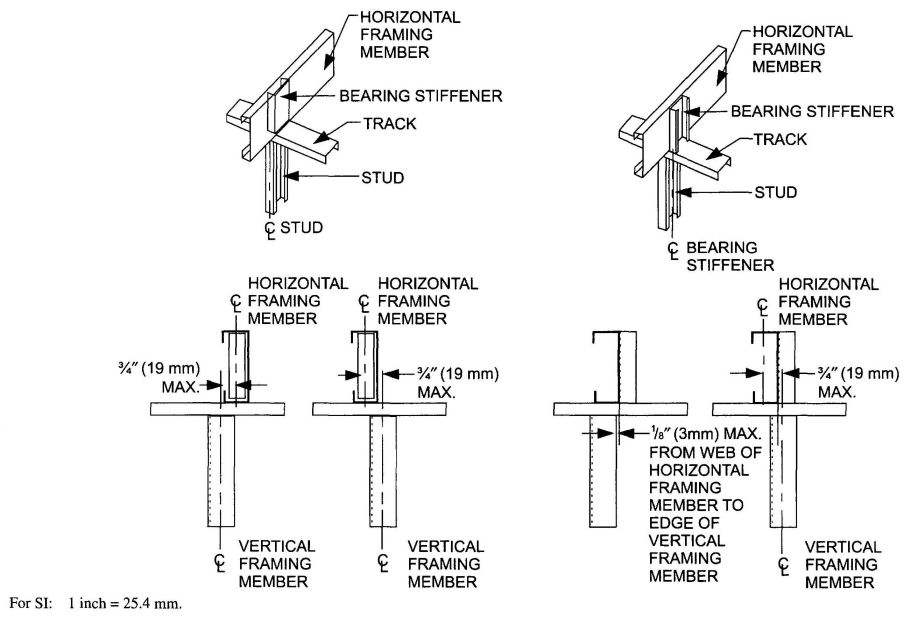
FIGURE R505.1.2
IN-LINE FRAMING
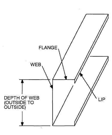
FIGURE R505.2(1)
C-SHAPED SECTION
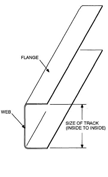
FIGURE R505.2(2)
TRACK SECTION
| MEMBER DESIGNATIONa | WEB DEPTH (inches) | MINIMUM FLANGE WIDTH (inches) | MAXIMUM FLANGE WIDTH (inches) | MINIMUM LIP SIZE (inches) |
|---|---|---|---|---|
| For SI: 1 inch = 25.4 mm, 1 mil = 0.0254 mm. | ||||
| a. The member designation is defined by the first number representing the member depth in 0.01 inch, the letter “S” representing a stud or joist member, the second number representing the flange width in 0.01 inch, and the letter “t” shall be a number representing the minimum base metal thickness in mils [See Table R505.2.(2)]. | ||||
| 550S162-t | 5.5 | 1.625 | 2 | 0.5 |
| 800S162-t | 8 | 1.625 | 2 | 0.5 |
| 1000S162-t | 10 | 1.625 | 2 | 0.5 |
| 1200S162-t | 12 | 1.625 | 2 | 0.5 |
| DESIGNATION THICKNESS (mils) | MINIMUM BASE STEEL THICKNESS (inches) |
|---|---|
| For SI: 1 inch = 25.4 mm, 1 mil = 0.0254 mm. | |
| 33 | 0.0329 |
| 43 | 0.0428 |
| 54 | 0.0538 |
| 68 | 0.0677 |
| 97 | 0.0966 |
R505.2.2 Identification. Load-bearing cold-formed steel framing members shall have a legible label stencil, stamp or embossment with the following information as a minimum:
R505.2.3 Corrosion protection. Load-bearing cold-formed steel framing shall have a metallic coating complying with ASTM A 1003 and one of the following:
R505.2.4 Fastening requirements. Screws for steel-to-steel connections shall be installed with a minimum edge distance and center-to-center spacing of ½ inch (12.7 mm), shall be self-drilling tapping, and shall conform to ASTM C 1513. Floor sheathing shall be attached to cold-formed steel joists with minimum No. 8 self-drilling taping screws that conform to ASTM C 1513. Screws attaching floor-sheathing to cold-formed steel joists shall have a minimum head diameter of 0.292 inch (7.4 mm) with countersunk heads and shall be installed with a minimum edge distance of 3/8 inch (9.5 mm). Gypsum board ceilings shall be attached to cold-formed steel joists with minimum No. 6 screws conforming to ASTM C 954 or ASTM C 1513 with a bugle head style and shall be installed in accordance with Section R702. For all connections, screws shall extend through the steel a minimum of three exposed threads. All fasteners shall have rust inhibitive coating suitable for the installation in which they are being used, or be manufactured from material not susceptible to corrosion.
Where No. 8 screws are specified in a steel-to-steel connection, the required number of screws in the connection is permitted to be reduced in accordance with the reduction factors in Table R505.2.4 when larger screws are used or when one of the sheets of steel being connected is thicker than 33 mils (0.84 mm). When applying the reduction factor, the resulting number of screws shall be rounded up.
| SCREW SIZE | THINNEST CONNECTED STEEL SHEET (mils) | |
|---|---|---|
| 33 | 43 | |
| For SI: 1 mil = 0.0254 mm. | ||
| 8 | 1.0 | 0.67 |
| 10 | 0.93 | 0.62 |
| 12 | 0.86 | 0.56 |
R505.2.5 Web holes, web hole reinforcing and web hole patching. Web holes, web hole reinforcing, and web hole patching shall be in accordance with this section.
R505.2.5.1 Web holes. Web holes in floor joists shall comply with all of the following conditions:
Framing members with the web holes not conforming to the above requirements shall be reinforced in accordance with Section R505.2.5.2, patched in accordance with Section R505.2.5.3 or designed in accordance with accepted engineering practices.
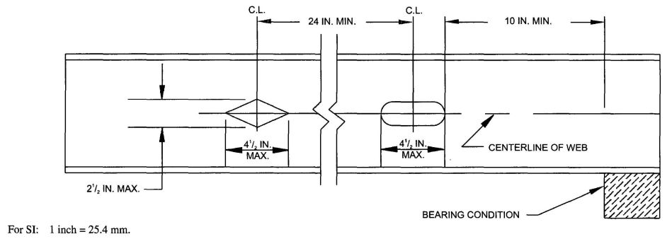
FIGURE R505.2.5.1
FLOOR JOIST WEB HOLES
R505.2.5.2 Web hole reinforcing. Reinforcement of web holes in floor joists not conforming to the requirements of Section R505.2.5.1 shall be permitted if the hole is located fully within the center 40 percent of the span and the depth and length of the hole does not exceed 65 percent of the flat width of the web. The reinforcing shall be a steel plate or C-shape section with a hole that does not exceed the web hole size limitations of Section R505.2.5.1 for the member being reinforced. The steel reinforcing shall be the same thickness as the receiving member and shall extend at least 1 inch (25.4 mm) beyond all edges of the hole. The steel reinforcing shall be fastened to the web of the receiving member with No. 8 screws spaced no more than 1 inch (25.4 mm) center-to-center along the edges of the patch with minimum edge distance of ½ inch (12.7 mm).
R505.2.5.3 Hole patching. Patching of web holes in floor joists not conforming to the requirements in Section R505.2.5.1 shall be permitted in accordance with either of the following methods:
R505.3 Floor construction. Cold-formed steel floors shall be constructed in accordance with this section.
R505.3.1 Floor to foundation or load-bearing wall connection. Cold-formed steel framed floors shall be anchored to foundations, wood sills or load-bearing walls in accordance with Table R505.3.1(1) and Figure R505.3.1.(1), R505.3.1(2), R505.3.1(3), R505.3.1(4), R505.3.1(5) or R505.3.1(6). Anchor bolts shall be located not more than 12 inches (305 mm) from corners or the termination of bottom tracks. Continuous cold-formed steel joists supported by interior load-bearing walls shall be con
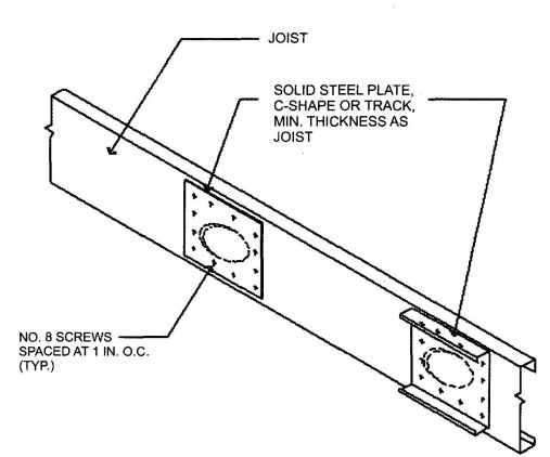
FIGURE R505.2.5.3
WEB HOLE PATCH
structed in accordance with Figure R505.3.1(7). Lapped cold-formed steel joists shall be constructed in accordance with Figure R505.3.1(8). End floor joists constructed on foundation walls parallel to the joist span shall be doubled unless a C-shaped bearing stiffener, sized in accordance with Section R505.3.4, is installed web-to-web with the floor joist beneath each supported wall stud, as shown in Figure R505.3.1(9). Fastening of cold-formed steel joists to other framing members shall be in accordance with Section R505.2.4 and Table R505.3.1(2).
R505.3.2 Minimum floor joist sizes. Floor joist size and thickness shall be determined in accordance with the limits set forth in Table R505.3.2(1) for single spans, and Tables R505.3.2(2) and R505.3.2(3) for multiple spans. When continuous joist members are used, the interior bearing supports shall be located within 2 feet (610 mm) of mid-span of the cold-formed steel joists, and the individual spans shall not exceed the spans in Table R505.3.2(2) or R505.3.2(3), as applicable. Floor joists shall have a bearing support length of not less than 1½ inches (38 mm) for exterior wall supports and 3½ inches (89 mm) for interior wall supports. Tracks shall be a minimum of 33 mils (0.84 mm) thick except when used as part of a floor header or trimmer in accordance with Section R505.3.8. Bearing stiffeners shall be installed in accordance with Section R505.3.4.
R505.3.3 Joist bracking and blocking. Joist bracing and blocking shall be in accordance with this section.
R505.3.3.1 Joist top flange bracing. The top flanges of cold-formed steel joists shall be laterally braced by the application of floor sheathing fastened to the joists in accordance with Section R505.2.4 and Table R505.3.1(2).
| FRAMING CONDITION | BASIC WIND SPEED (mph) AND EXPOSURE | |
|---|---|---|
| 85 mph Exposure C or less than 110 mph Exposure B | Less than 110 mph Exposure C | |
| For SI: 1 inch = 25.4 mm, 1 pound per squares foot = 0.0479 kPa, 1 mile per hour = 0.447 m/s. 1 foot = 304.8 mm. | ||
| a. Anchor bolts are to be located not more than 12 inches from corners or the termination of bottom tracks (e.g., at door openings or corners). Bolts extend a minimum of 15 inches into masonry or 7 inches into concrete. Anchor bolts connecting cold-formed steel framing to the foundation structure are to be installed so that the distance from the center of the bolt hole to the edge of the connected member is not less than one and one-half bolt diameters. | ||
| b. All screw sizes shown are minimum. | ||
| Floor joist to wall track of exterior wall per Figure R505.3.1(1) | 2-No. 8 screws | 3-No. 8 screws |
| Rim track or end joist to load-bearing wall top track per Figure R 505.3.1(1) | 1-No. 8 screw at 24 inches o.c. | 1-No. 8 screw at 24 inches o.c. |
| Rim track or end joist to wood sill per Figure R505.3.1(2) | Steel plate spaced at 4 feet o.c. with 4-No. 8 screws and 4-10d or 6-8d common nails | Steel plate spaced at 2 feet o.c. with 4-No. 8 screws and 4-10d or 6-8d common nails |
| Rim track or end joist to foundation per Figure R505.3.1(3) | ½ inch minimum diameter anchor bolt and clip angle spaced at 6 feet o.c. with 8-No. 8 screws | ½ inch minimum diameter anchor bolt and clip angle spaced at 4 feet o.c. with 8-No. 8 screws |
| Cantilevered joist to foundation per Figure R505.3.1(4) | ½ inch minimum diameter anchor bolt and clip angle spaced at 6 feet o.c. with 8-No. 8 screws | ½ inch minimum diameter anchor bolt and clip angle spaced at 4 feet o.c. with 8-No. 8 screws |
| Cantilevered joist to wood sill per Figure R505.3.1(5) | Steel plate spaced at 4 feet o.c. with 4-No. 8 screws and 4-10d or 6-8d common nails | Steel plate spaced at 2 feet o.c. with 4-No. 8 screws and 4-10d or 6-8d common nails |
| Cantilevered joist to exterior load-bearing wall track per Figure R505.3.1(6) | 2-No. 8 screws | 3-No. 8 screws |
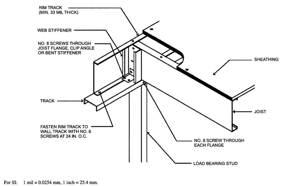
FIGURE 505.3.1(1)
FLOOR TO EXTERIOR LOAD-BEARING WALL STUD CONNECTION
| DESCRIPTION OF BUILDING ELEMENTS | NUMBER AND SIZE OF FASTENERS | SPACING OF FASTENERS |
|---|---|---|
| For SI: 1 inch = 25.4 mm. | ||
| a. All screw sizes shown are minimum. | ||
| Floor joist to track of an interior load-bearing wall per Figures R505.3.1(7) and R505.3.1(8) |
2 No. 8 screws | Each joist |
| Floor joist to track at end of joist | 2 No. 8 screws | One per flange or two per bearing stiffener |
| Subfloor to floor joists | No. 8 screws | 6 in. o.c. on edges and 12 in. o.c. at intermediate supports |
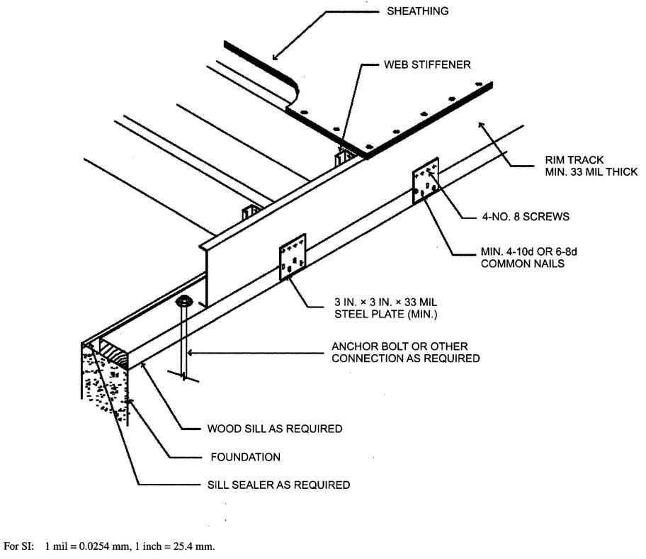
FIGURE R505.3.1(2)
FLOOR TO WOOD SILL CONNECTION
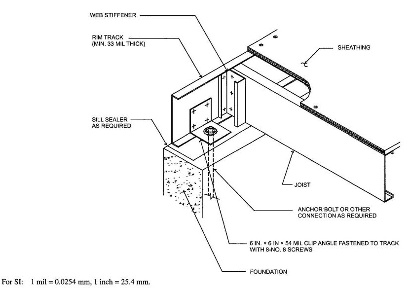
FIGURE R505.3.1(3)
FLOOR TO FOUNDATION CONNECTION
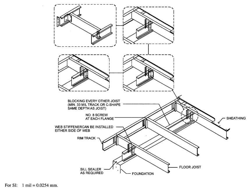
FIGURE R505.3.1(4)
CANTILEVERED FLOOR TO FOUNDATION CONNECTION
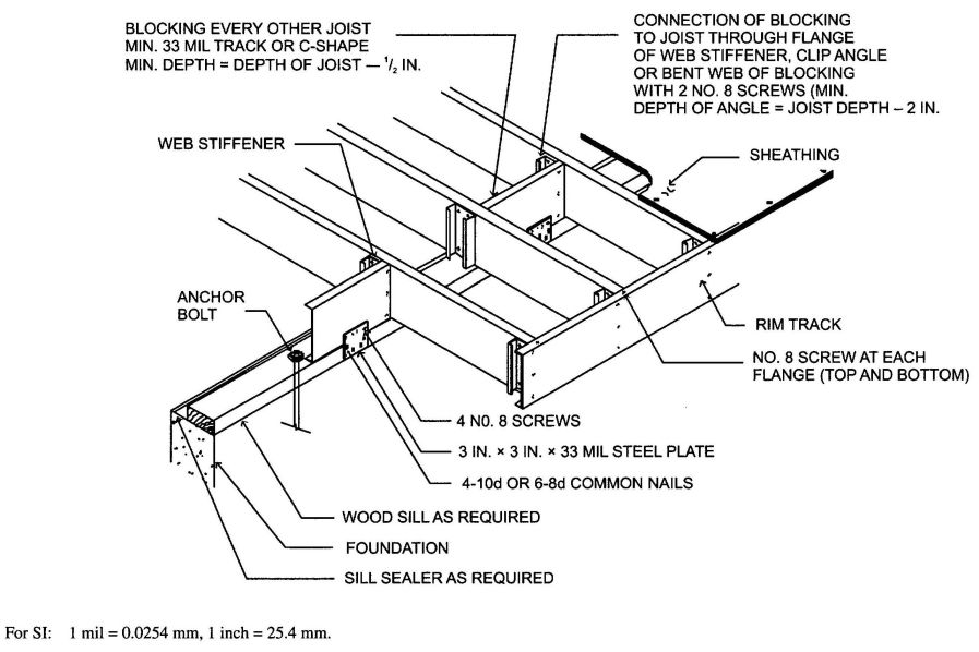
FIGURE R505.3.1(5)
CANTILEVERED FLOOR TO WOOD SILL CONNECTION
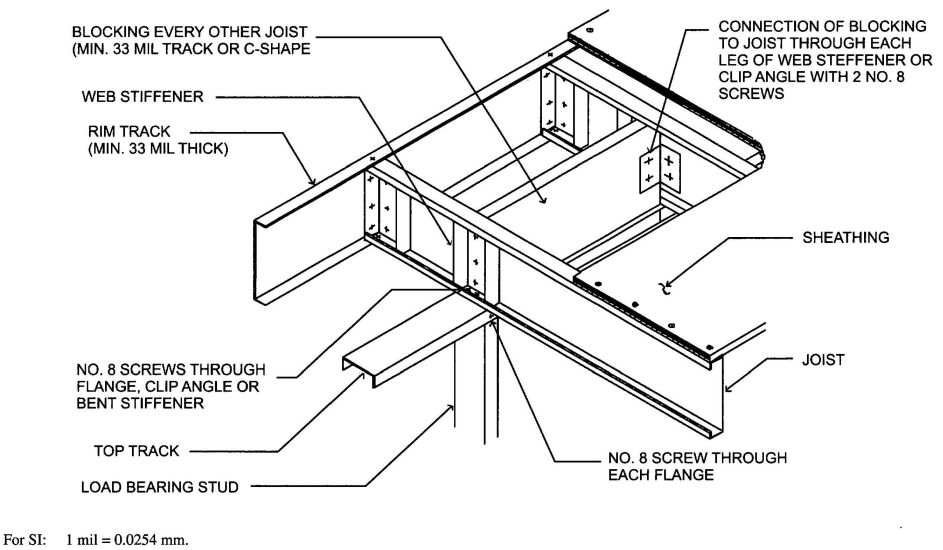
FIGURE R505.3.1(6)
CANTILEVERED FLOOR TO EXTERIOR LOAD-BEARING WALL CONNECTION
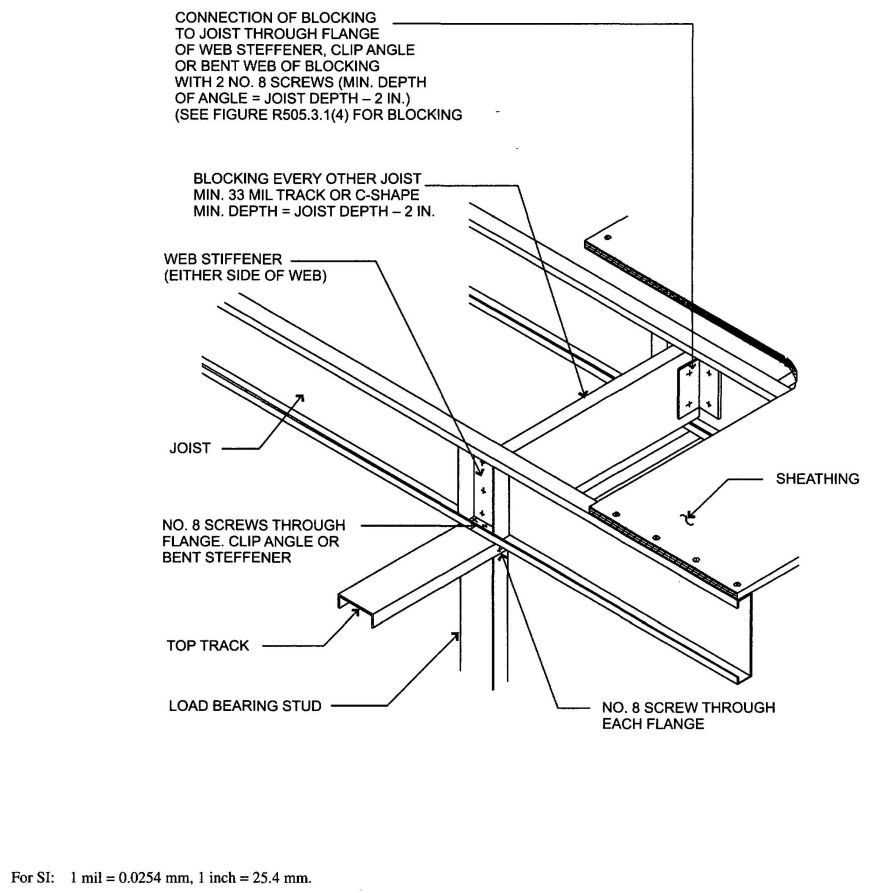
FIGURE R505.3.1(7)
CONTINUOUS SPAN JOIST SUPPORTED ON INTERIOR LOAD-BEARING WALL
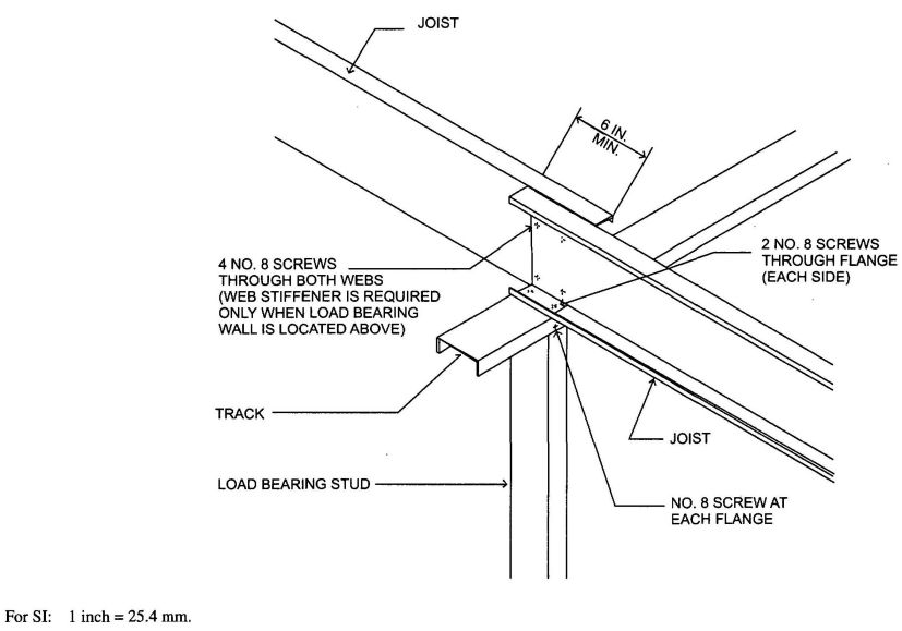
FIGURE R505.3.1(8)
LAPPED JOISTS SUPPORTED ON INTERIOR LOAD-BEARING WALL
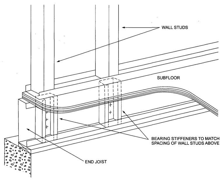
FIGURE R505.3.1(9)
BEARING STIFFENERS FOR END JOISTS
| JOIST DESIGNATION | 30 PSF LIVE LOAD | 40 PSF LIVE LOAD | ||||||
|---|---|---|---|---|---|---|---|---|
| Spacing (inches) | Spacing (inches) | |||||||
| 12 | 16 | 19.2 | 24 | 12 | 16 | 19.2 | 24 | |
| For SI: 1 inch = 25.4 mm, 1 foot = 304.8 mm, 1 pound per square foot = 0.0479 kPa. | ||||||||
| a. Deflection criteria: L/480 for live loads, L/240 for total loads. | ||||||||
| b. Floor dead load = 10 psf. | ||||||||
| c. Table provides the maximum clear span in feet and inches. | ||||||||
| d. Bearing stiffeners are to be installed at all support points and concentrated loads. | ||||||||
| 550S162-33 | 11′;-7″ | 10′;-7″ | 9′;-6″ | 8′;-6″ | 10′;-7″ | 9′;-3″ | 8′;-6″ | 7′;-6″ |
| 550S162-43 | 12′;-8″ | 11′;-6″ | 10′;-10″ | 10′;-2″ | 11′;-6″ | 10′;5″ | 9′;-10″ | 9′;-1″ |
| 550S162-54 | 13′;-7″ | 12′;-4″ | 11′;-7″ | 10′;-9″ | 12′;4″ | 11′;-2″ | 10′;-6″ | 9′;-9″ |
| 550S162-68 | 14′;-7″ | 13′;-3″ | 12′;-6″ | 11′;-7″ | 13′;-3″ | 12′;-0″ | 11′;-4″ | 10′;-6″ |
| 550S162-97 | 16′;-2″ | 14′;-9″ | 13′;-10″ | 12′;-10″ | 14′;-9″ | 13′;-4″ | 12′;-7″ | 11′;8″ |
| 800S162-33 | 15′;8″ | 13′;-11″ | 12′;-9″ | 11′;-5″ | 14′;-3″ | 12′;-5″ | 11′;-3″ | 9′;-0″ |
| 800S162-43 | 17′;-1″ | 15′;-6″ | 14′;-7″ | 13′;-7″ | 15′;-6″ | 14′;-1″ | 13′;-3″ | 12′;-4″ |
| 800S162-54 | 18′;-4″ | 16′;-8″ | 15′;-8″ | 14′;-7″ | 16′;-8″ | 15′;-2″ | 14′;-3″ | 13′;-3″ |
| 800S162-68 | 19′;-9″ | 17′;-11″ | 16′;-10″ | 15′;-8″ | 17′;-11″ | 16′;-3″ | 15′;-4″ | 14′;-2″ |
| 800S162-97 | 22′;-0″ | 20′;-0″ | 16′;-10″ | 17′;-5″ | 20′;-0″ | 18′;-2″ | 17′;-1″ | 15′;-10″ |
| 1000S162-43 | 20′;-6″ | 18′;-8″ | 17′;-6″ | 15′;-8″ | 18′;-8″ | 16′;-11″ | 15′;-6″ | 13′;-11″ |
| 1000S162-54 | 22′;-1″ | 20′;-0″ | 18′;-10″ | 17′;-6″ | 20′;-0″ | 18′;-2″ | 17′;-2″ | 15′;-11″ |
| 1000S162-68 | 23′;-9″ | 21′;-7″ | 20′;-3″ | 18′;-10″ | 21′;-7″ | 19′;-7″ | 18′;-5″ | 17′;-1″ |
| 1000S162-97 | 26′;-6″ | 24′;-1″ | 22′;-8″ | 21′;-0″ | 24′;-1″ | 21′;-10″ | 20′;-7″ | 19′;-1″ |
| 1200S162-43 | 23′;-9″ | 20′;-10″ | 19′;-0″ | 16′;-8″ | 21′;-5″ | 18′;-6″ | 16′;-6″ | 13′;-2″ |
| 1200S162-54 | 25′;-9″ | 23′;-4″ | 22′;-0″ | 20′;-1″ | 23′;-4″ | 21′;-3″ | 20′;-0″ | 17′;-10″ |
| 1200S162-68 | 27′;-8″ | 25′;-1″ | 23′;-8″ | 21′;-11″ | 25′;-1″ | 22″-10″ | 21′;-6″ | 21′;-1″ |
| 1200S162-97 | 30′;-11″ | 28′;-1″ | 26′;-5″ | 24′;-6″ | 28′;-1″ | 25′;-6″ | 24′;-0″ | 22′;-3″ |
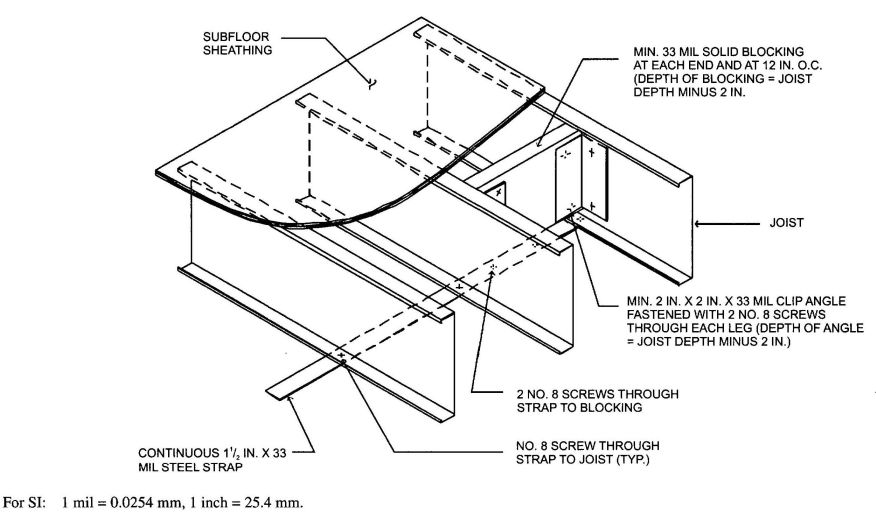
FIGURE R505.3.3.2(1)
JOIST BLOCKING (SOLID)
| JOIST DESIGNATION | 30 PSF LIVE LOAD | 40 PSF LIVE LOAD | ||||||
|---|---|---|---|---|---|---|---|---|
| Spacing (inches) | Spacing (inches) | |||||||
| 12 | 16 | 19.2 | 24 | 12 | 16 | 19.2 | 24 | |
| For SI:1 inch = 25.4 mm, 1 foot = 304.8 mm,1 pound per square foot = 0.0479 kPa. | ||||||||
| a. Deflection criteria: L/480 for live loads, L/240 for total loads. | ||||||||
| b. Floor dead load = 10 psf. | ||||||||
| c. Table provides the maximum clear span in feet and inches to either side of the interior support. | ||||||||
| d. Interior bearing supports for multiple span joists consist of structural (bearing) walls or beams. | ||||||||
| e. Interior supports shall be located within 2 feet of mid-span provided that each of the resulting spans does not exceed the appropriate maximum span shown in the table above. | ||||||||
| 550S162-33 | 12′;-1″ | 10′;-5″ | 9′;-6″ | 8′;-6″ | 10′;-9″ | 9′;-3″ | 8′;-6″ | 7′;-6″ |
| 550S162-43 | 14′;-5″ | 12′;-5″ | 11′;-4″ | 10′;-2″ | 12′;-9″ | 11′;-11″ | 10′;-1″ | 9′;-0″ |
| 550S162-54 | 16′;-3″ | 14′;1″ | 12′;-10″ | 11′;-6″ | 14′;-5″ | 12′;-6″ | 11′;-5″ | 10′;-2″ |
| 550S162-68 | 19′;-7″ | 17′;-9″ | 16′;-9″ | 15′;-6″ | 17′;-9″ | 16′;-2″ | 15′;-2″ | 14′;-1″ |
| 550S162-97 | 21′;-9″ | 19′;-9″ | 18′;-7″ | 17′;-3″ | 19′;-9″ | 17′;-11″ | 16′;-10″ | 15′;-4″ |
| 800S162-33 | 14′;-8″ | 11′;-10″ | 10′;-4″ | 8′;-8″ | 12′;-4″ | 9′;-11″ | 8′;-7″ | 7′;-2″ |
| 800S162-43 | 20′;-0″ | 17′;-4″ | 15′;9″ | 14′;-1″ | 17′;-9″ | 15′;-4″ | 14′;-0″ | 12′;-0″ |
| 800S162-54 | 23′;-7″ | 20′;-5″ | 18′;-8″ | 16′;-8″ | 21′;-0″ | 18′;-2″ | 16′;-7″ | 14′;-10″ |
| 800S162-68 | 26′;-5″ | 23′;-1″ | 21′;-0″ | 18′;-10″ | 23′;-8″ | 20′;-6″ | 18′;-8″ | 16′;-9″ |
| 800S162-97 | 29′;-6″ | 26′;-10″ | 25′;-3″ | 22′;-8″ | 26′;-10″ | 24′;-4″ | 22′;-6″ | 20′;-2″ |
| 1000S162-43 | 22′;-2″ | 18′;-3″ | 16′;-0″ | 13′;-7″ | 18′;-11″ | 15′;-5″ | 13′;-6″ | 11′;-5″ |
| 1000S162-54 | 26′;-2″ | 22′;-8″ | 20′;-8″ | 18′;-6″ | 23′;-3″ | 20′;-8″ | 18′;-6″ | 167′;-5″ |
| 1000S162-68 | 31′;-5″ | 27′;-2″ | 24′;-10″ | 22′;-2″ | 27′;-11″ | 24′;-2″ | 22′;-1″ | 19′;9″ |
| 1000S162-97 | 35′;-6″ | 32′;-3″ | 29′;-11″ | 26′;-9″ | 32′;-3″ | 29′;-2″ | 26′;-7″ | 23′;-9″ |
| 1200S162-43 | 21′;-8″ | 17′;-6″ | 15′;-3″ | 12′;-10″ | 18′;-3″ | 14′;-8″ | 12′;-8″ | 10′;-62 |
| 1200S162-54 | 28′;-5″ | 24′;-8″ | 22′;-6″ | 19′;-6″ | 25′;-3″ | 21′;-11″ | 19′;-4″ | 16′;-6″ |
| 1200S162-68 | 33′;-7″ | 29′;-1″ | 26′;-6″ | 23′;-9″ | 29′;-10″ | 25′;-10″ | 23′;-7″ | 21′;-1″ |
| 1200S162-97 | 41′;-5″ | 37′;-8″ | 34′;-6″ | 30′;-10″ | 37′;8″ | 33′;-6″ | 30′;-7″ | 27′;-5″ |
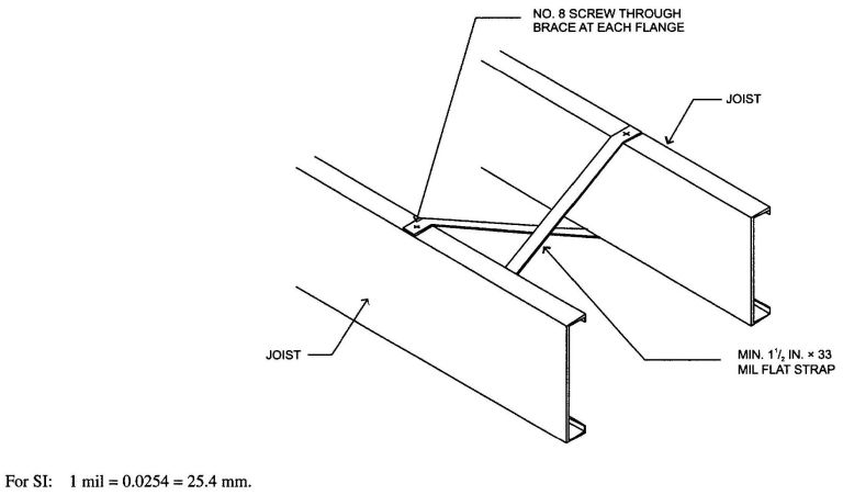
FIGURE R505.3.3.2(2)
JOIST BLOCKING (STRAP)
| JOIST DESIGNATION | 30 PSF LIVE LOAD | 40 PSF LIVE LOAD | ||||||
|---|---|---|---|---|---|---|---|---|
| Spacing (inches) | Spacing (inches) | |||||||
| 12 | 16 | 19.2 | 24 | 12 | 16 | 19.2 | 24 | |
| For SI: 1 inch = 25.4 mm, 1 foot = 304.8 mm, 1 pound per square foot = 0.0479 kPa. | ||||||||
| a. Deflection criteria: L/480 for live loads, L/240 for total loads. | ||||||||
| b. Floor dead load = 10 psf. | ||||||||
| c. Table provides the maximum clear span in feet and inches to either side of the interior support. | ||||||||
| d. Interior bearing supports for multiple span joists consist of structural (bearing) walls or beams. | ||||||||
| e. Bearing stiffeners are to be installed at all support points and concentrated loads. | ||||||||
| f. Interior supports shall be located within 2 feet of mid-span provided that each of the resulting spans does not exceed the appropriate maximum span shown in the table above. | ||||||||
| 550S162-33 | 13′;-11″ | 12′;-0″ | 11′;-0″ | 9′;-3″ | 12′;-3″ | 10′;-8″ | 9′;-7″ | 8′;-4″ |
| 550S162-43 | 16′;-3″ | 14′;-1″ | 12′;-10″ | 11′;-6″ | 14′;-6″ | 12′;-6″ | 11′;-5″ | 10′;-3″ |
| 550S162-54 | 18′;-2″ | 16′;-6″ | 15′;-4″ | 13′;-8″ | 16′;-6″ | 14′;-11″ | 13′;-7″ | 12′;-2″ |
| 550S162-68 | 19′;-6″ | 17′;-9″ | 16′;-8″ | 15′;-6″ | 17″-9″ | 16′;-1″ | 15′;-2″ | 14′;-0″ |
| 550S162-97 | 21′;-9″ | 19′;-9″ | 18′;-6″ | 17′;-2″ | 19′;-8″ | 17′;-10″ | 16′;-8″ | 15′;-8″ |
| 800S162-33 | 15′;-6″ | 12′;-6″ | 10′;-10″ | 9′;-1″ | 13′;-0″ | 10′;-5″ | 8′;-11″ | 6′;9″ |
| 800S162-43 | 22′;-0″ | 19′;-1″ | 17′;-5″ | 15′;-0″ | 19′;-7″ | 16′;-11″ | 14′;-10″ | 12′;-8″ |
| 800S162-54 | 24′;-6″ | 22′;-4″ | 20′;-6″ | 17′;-11″ | 22′;-5″ | 19′;-9″ | 17′;-11″ | 15′;-10″ |
| 800S162-68 | 26′;-6″ | 24′;-1″ | 22′;-8″ | 21′;-0″ | 24′;-1″ | 21′;-10″ | 20′;-7″ | 19′;-2″ |
| 800S162-97 | 29′;-9″ | 26′;-8″ | 25′;-2″ | 23′;-5″ | 26′;-8″ | 24′;-3″ | 22′;-11″ | 21′;-4″ |
| 1000S162-43 | 23′;-6″ | 19′;-2″ | 16′;-9″ | 14′;-2″ | 19′;-11″ | 16′;-2″ | 14′;-0″ | 11′;-9″ |
| 1000S162-54 | 28′;-2″ | 23′;-10″ | 21′;-7″ | 18′;-11″ | 24′;-8″ | 20′;-11″ | 18′;-9″ | 18′;-4″ |
| 1000S162-68 | 31′;-10″ | 28′;-11″ | 27′;-2″ | 25′;-3″ | 28′;-11″ | 26′;-3″ | 24′;-9″ | 22′;-9″ |
| 1000S162-97 | 35′;-4″ | 32′;-1″ | 30′;-3″ | 28′;-1″ | 32′;-1″ | 29′;-2″ | 27′;-6″ | 25′;-6″ |
| 1200S162-43 | 22′;-11″ | 18′;-5″ | 16′;-0″ | 13′;-4″ | 19′;-2″ | 15′;-4″ | 13′;-2″ | 10′;-6″ |
| 1200S162-54 | 32′;-8″ | 28′;-1″ | 24′;-9″ | 21′;-2″ | 29′;-0″ | 23′;-10″ | 20′;-11″ | 17′;-9″ |
| 1200S162-68 | 37′;-1″ | 32′;-5″ | 29′;-4″ | 25′;-10″ | 33′;-4″ | 28′;-6″ | 25′;-9″ | 22′;-7″ |
| 1200S162-97 | 41′;-2″ | 37′;-6″ | 35′;-3″ | 32′;-9″ | 37′;-6″ | 34′;-1″ | 32′;-1″ | 29′;-9″ |
R505.3.3.2 Joist bottom flange bracing/blocking. Floor joists with spans that exceed 12 feet (3658 mm) shall have the bottom flanges laterally braced in accordance with one of the following:
R505.3.3.3 Blocking at interior bearing supports. Blocking is not required for continuous back-to-back floor joists at bearing supports. Blocking shall be installed between every other joist for single continuous floor joists across bearing supports in accordance with Figure R505.3.1(7). Blocking shall consist of C-shape or track section with a minimum thickness of 33 mils (0.84 mm). Blocking shall be fastened to each adjacent joist through a 33-mil (0.84 mm) clip angle, bent web of blocking or flanges of web stiffeners with two No. 8 screws on each side. The minimum depth of the blocking shall be equal to the depth of the joist minus 2 inches (51 mm). The minimum length of the angle shall be equal to the depth of the joist minus 2 inches (51 mm).
R505.3.3.4 Blocking at cantilevers. Blocking shall be installed between every other joist over cantilever bearing supports in accordance with Figure R505.3.1(4), R505.3.1(5) or R505.3.1(6). Blocking shall consist of
189C-shape or track section with minimum thickness of 33 mils (0.84 mm). Blocking shall be fastened to each adjacent joist through bent web of blocking, 33 mil clip angle or flange of web stiffener with two No.8 screws at each end. The depth of the blocking shall be equal to the depth of the joist. The minimum length of the angle shall be equal to the depth of the joist minus 2 inches (51 mm). Blocking shall be fastened through the floor sheathing and to the support with three No. 8 screws (top and bottom).
R505.3.4 Bearing stiffeners. Bearing stiffeners shall be installed at each joist bearing location in accordance with this section, except for joists lapped over an interior support not carrying a load-bearing wall above. Floor joists supporting jamb studs with multiple members shall have two bearing stiffeners in accordance with Figure R505.3.4(1). Bearing stiffeners shall be fabricated from a C-shaped, track or clip angle member in accordance with the one of following:
The minimum length of a bearing stiffener shall be the depth of member being stiffened minus 3/8 inch (9.5 mm). Each bearing stiffener shall be fastened to the web of the member it is stiffening as shown in Figure R505.3.4(2). Each clip angle bearing stiffener shall also be fastened to the web of the adjacent rim track using the fastener pattern shown in Figure R505.3.4(2). No. 8 screws shall be used for C-shaped and track members of any thickness and for clip angle members with a designation thickness less than or equal to 54. No. 10 screws shall be used for clip angle members with a designation thickness greater than 54.
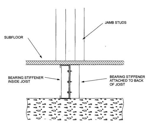
FIGURE R505.3.4(1)
BEARING STIFFENERS UNDER JAMB STUDS
R505.3.5 Cutting and notching. Flanges and lips of load-bearing cold-formed steel floor framing members shall not be cut or notched.
R505.3.6 Floor cantilevers. Floor cantilevers for the top floor of a two- or three-story building or the first floor of a one-story building shall not exceed 24 inches (610 mm). Cantilevers, not exceeding 24 inches (610 mm) and supporting two stories and roof (i.e., first floor of a two-story building), shall also be permitted provided that all cantilevered joists are doubled (nested or back-to-back). The doubled cantilevered joists shall extend a minimum of 6 feet (1829 mm) toward the inside and shall be fastened with a minimum of two No. 8 screws spaces at 24 inches (610 mm) on center through the webs (for back-to-back) or flanges (for nested joists).
R505.3.7 Splicing. Joists and other structural members shall not be spliced. Splicing of tracks shall conform to Figure R505.3.7.
R505.3.8 Framing of floor openings. Openings in floors shall be framed with header and trimmer joists. Header joist spans shall not exceed 6 feet (1829 mm) or 8 feet (2438 mm) in length in accordance with Figure R505.3.8(1) or R505.3.8(2), respectively. Header and trimmer joists shall be fabricated from joist and track members, having a minimum size and thickness at least equivalent to the adjacent floor joists and shall be installed in accordance with Figures R505.3.8(1), R505.3.8(2), R505.3.8(3), and R505.3.8(4). Each header joist shall be connected to both the header and trimmer joists with four 2-inch-by-2-inch (51 mm by 51 mm) clip angles. Each clip angle shall be fastened to both the header and trimmer joists with four No. 8 screws, evenly spaced, through each leg of the clip angle. The clip angles shall have thickness not less than that of the floor joist. Each track section for a built-up header or trimmer joist shall extend the full length of the joist (continuous).
| JOIST DESIGNATION | MINIMUM THICKNESS (mils) OF 2-INCH × 2-INCH (51 mm × 51 mm) CLIP ANGLE | |||||||||||
|---|---|---|---|---|---|---|---|---|---|---|---|---|
| Top floor | Bottom floor in 2 story Middle floor in 3 story | Bottom floor in 3 story | ||||||||||
| Joist spacing (inches) | Joist spacing (inches) | Joist spacing (inches) | ||||||||||
| 12 | 16 | 19.2 | 24 | 12 | 16 | 19.2 | 24 | 12 | 16 | 19.2 | 24 | |
| For SI: 1 mil = 0.254 mm, 1 inch = 25.4 mm, 1 pound per square foot = 0.0479kPa.. | ||||||||||||
| 800S162-33 | 43 | 43 | 43 | 43 | 43 | 54 | 68 | 68 | 68 | 97 | 97 | — |
| 800S162-43 | 43 | 43 | 43 | 43 | 54 | 54 | 68 | 68 | 97 | 97 | 97 | 97 |
| 800S162-54 | 43 | 43 | 43 | 43 | 43 | 54 | 68 | 68 | 68 | 97 | 97 | — |
| 800S162-68 | 43 | 43 | 43 | 43 | 43 | 43 | 54 | 68 | 54 | 97 | 97 | — |
| 800S162-97 | 43 | 43 | 43 | 43 | 43 | 43 | 43 | 43 | 43 | 43 | 54 | 97 |
| 1000S162-43 | 43 | 43 | 43 | 43 | 54 | 68 | 97 | 97 | 97 | — | — | — |
| 1000S162-54 | 43 | 43 | 43 | 43 | 54 | 68 | 68 | 97 | 97 | 97 | — | — |
| 1000S162-68 | 43 | 43 | 43 | 43 | 54 | 68 | 97 | 97 | 97 | — | — | — |
| 1000S162-97 | 43 | 43 | 43 | 43 | 43 | 43 | 43 | 54 | 43 | 68 | 97 | — |
| 1200S162-43 | 43 | 54 | 54 | 54 | 97 | 97 | 97 | 97 | — | — | — | — |
| 1200S162-54 | 54 | 54 | 54 | 54 | 97 | 97 | 97 | 97 | — | — | — | — |
| 1200S162-68 | 43 | 43 | 54 | 54 | 68 | 97 | 97 | 97 | — | — | — | — |
| 1200S162-97 | 43 | 43 | 43 | 43 | 43 | 54 | 68 | 97 | 97 | — | — | — |
| JOIST DESIGNATION | MINIMUM THICKNESS (mils) OF 2-INCH × 2-INCH (51 mm × 51 mm) CLIP ANGLE | |||||||||||
|---|---|---|---|---|---|---|---|---|---|---|---|---|
| Top floor | Bottom floor in 2 story Middle floor in 3 story | Bottom floor in 3 story | ||||||||||
| Joist spacing (inches) | Joist spacing (inches) | Joist spacing (inches) | ||||||||||
| 12 | 16 | 19.2 | 24 | 12 | 16 | 19.2 | 24 | 12 | 16 | 19.2 | 24 | |
| For SI: 1 mil = 0.0254 mm, 1 inch = 25.4 mm, 1 pound per square foot = 0.0479kPa. | ||||||||||||
| 800S162-33 | 43 | 43 | 43 | 43 | 54 | 68 | 68 | 97 | 97 | 97 | 97 | — |
| 800S162-43 | 43 | 43 | 43 | 54 | 68 | 68 | 68 | 97 | 97 | 97 | 97 | — |
| 800S162-54 | 43 | 43 | 43 | 43 | 54 | 68 | 68 | 97 | 97 | 97 | — | — |
| 800S162-68 | 43 | 43 | 43 | 43 | 43 | 54 | 68 | 97 | 68 | 97 | 97 | — |
| 800S162-97 | 43 | 43 | 43 | 43 | 43 | 43 | 43 | 43 | 43 | 43 | 68 | 97 |
| 1000S162-43 | 54 | 54 | 54 | 54 | 68 | 97 | 97 | 97 | 97 | — | — | — |
| 1000S162-54 | 54 | 54 | 54 | 54 | 68 | 97 | 97 | 97 | 97 | — | — | — |
| 1000S162-68 | 43 | 43 | 54 | 68 | 68 | 97 | 97 | — | 97 | — | — | — |
| 1000S162-97 | 43 | 43 | 43 | 43 | 43 | 43 | 54 | 68 | 54 | 97 | — | — |
| 1200S162-43 | 54 | 68 | 68 | 68 | 97 | 97 | 97 | — | — | — | — | — |
| 1200S162-54 | 68 | 68 | 68 | 68 | 97 | 97 | — | — | — | — | — | — |
| 1200S162-68 | 68 | 68 | 68 | 68 | 97 | 97 | 97 | — | — | — | — | — |
| 1200S162-97 | 43 | 43 | 43 | 43 | 54 | 68 | 97 | — | 97 | — | — | — |
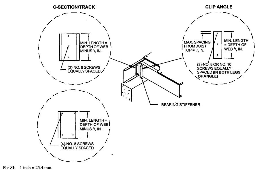
FIGURE R505.3.4(2)
BEARING STIFFENER
| JOIST DESIGNATION | MINIMUM THICKNESS (mils) OF 2-INCH × 2-INCH (51 mm × 51 mm) CLIP ANGLE | |||||||||||
|---|---|---|---|---|---|---|---|---|---|---|---|---|
| Top floor | Bottom floor in 2 story Middle floor in 3 story | Bottom floor in 3 story | ||||||||||
| Joist spacing (inches) | Joist spacing (inches) | Joist spacing (inches) | ||||||||||
| 12 | 16 | 19.2 | 24 | 12 | 16 | 19.2 | 24 | 12 | 16 | 19.2 | 24 | |
| For SI: 1 mil = 0.0254 mm, 1 inch = 25.4 mm, 1 pound per square foot = 0.0479kPa. | ||||||||||||
| 800S162-33 | 54 | 54 | 54 | 54 | 68 | 97 | 97 | 97 | 97 | — | — | — |
| 800S162-43 | 68 | 68 | 68 | 68 | 97 | 97 | 97 | 97 | — | — | — | — |
| 800S162-54 | 54 | 68 | 68 | 68 | 97 | 97 | 97 | 97 | — | — | — | — |
| 800S162-68 | 43 | 43 | 54 | 54 | 68 | 97 | 97 | 97 | 97 | — | — | — |
| 800S162-97 | 43 | 43 | 43 | 43 | 43 | 43 | 43 | 54 | 54 | 68 | 97 | — |
| 1000S162-43 | 97 | 68 | 68 | 68 | 97 | 97 | 97 | 97 | — | — | — | — |
| 1000S162-54 | 97 | 97 | 68 | 68 | 97 | 97 | 97 | — | — | — | — | — |
| 1000S162-68 | 68 | 97 | 97 | 97 | 97 | — | — | — | — | — | — | — |
| 1000S162-97 | 43 | 43 | 43 | 43 | 54 | 68 | 97 | 97 | — | — | — | — |
| 1200S162-43 | 97 | 97 | 97 | 97 | — | — | — | — | — | — | — | — |
| 1200S162-54 | — | 97 | 97 | 97 | — | — | — | — | — | — | — | — |
| 1200S162-68 | 97 | 97 | 97 | 97 | — | — | — | — | — | — | — | — |
| 1200S162-97 | 54 | 68 | 68 | 97 | 97 | — | — | — | — | — | — | — |
| JOIST DESIGNATION | MINIMUM THICKNESS (mils) OF 2-INCH × 2-INCH (51 mm × 51 mm) CLIP ANGLE | |||||||||||
|---|---|---|---|---|---|---|---|---|---|---|---|---|
| Top floor | Bottom floor in 2 story Middle floor in 3 story | Bottom floor in 3 story | ||||||||||
| Joist spacing (inches) | Joist spacing (inches) | Joist spacing (inches) | ||||||||||
| 12 | 16 | 19.2 | 24 | 12 | 16 | 19.2 | 24 | 12 | 16 | 19.2 | 24 | |
| For SI: 1 mil 0.0254 mm, 1 inch = 25.4 mm, 1 pound per square foot = 0.0479kPa. | ||||||||||||
| 800S162-33 | 68 | 68 | 68 | 68 | 97 | 97 | 97 | 97 | — | — | — | — |
| 800S162-43 | 97 | 97 | 97 | 97 | 97 | 97 | 97 | — | — | — | — | — |
| 800S162-54 | 97 | 97 | 97 | 97 | 97 | — | — | — | — | — | — | — |
| 800S162-68 | 68 | 68 | 68 | 97 | 97 | 97 | 97 | — | — | — | — | — |
| 800S162-97 | 43 | 43 | 43 | 43 | 43 | 54 | 68 | 97 | 97 | 97 | — | — |
| 1000S162-43 | 97 | 97 | 97 | 97 | — | — | — | — | — | — | — | — |
| 1000S162-54 | — | 97 | 97 | 97 | — | — | — | — | — | — | — | — |
| 1000S162-68 | 97 | 97 | — | — | — | — | — | — | — | — | — | — |
| 1000S162-97 | 68 | 68 | 68 | 68 | 97 | 97 | — | — | — | — | — | — |
| 1200S162-43 | 97 | 97 | 97 | 97 | — | — | — | — | — | — | — | — |
| 1200S162-54 | — | — | — | — | — | — | — | — | — | — | — | — |
| 1200S162-68 | — | — | — | — | — | — | — | — | — | — | — | — |
| 1200S162-97 | 97 | 97 | 97 | — | — | — | — | — | — | — | — | — |
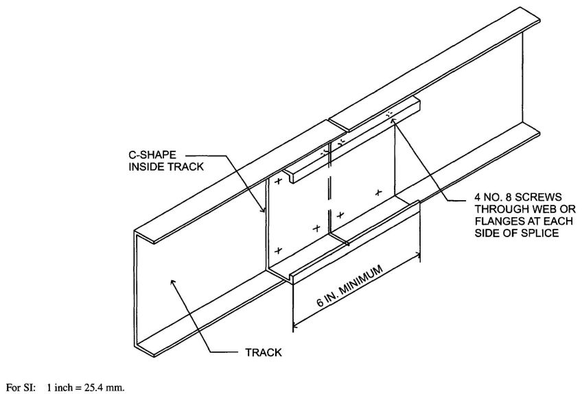
FIGURE R505.3.7
TRACK SPLICE
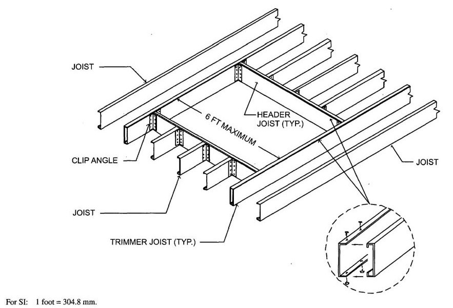
FIGURE R505.3.8(1)
COLD-FORMED STEEL FLOOR CONSTRUCTION: 6-FOOT FLOOR OPENING
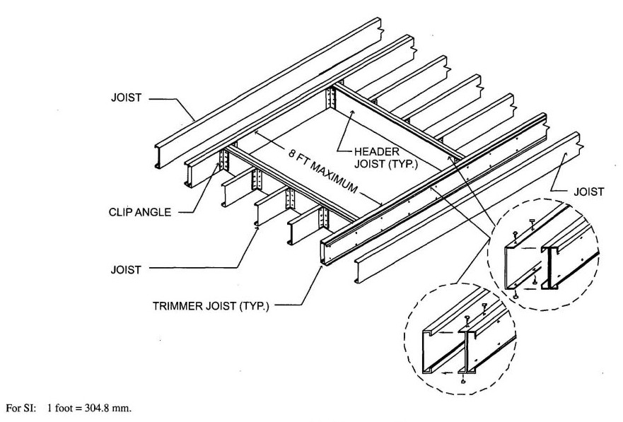
FIGURE R505.3.8(2)
COLD-FORMED STEEL FLOOR CONSTRUCTION: 8-FOOT FLOOR OPENING
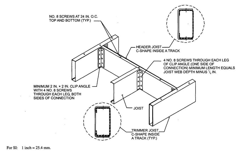
FIGURE R505.3.8(3)
COLD-FORMED STEEEL FLOOR CONSTRUCTION: FLOOR HEADER TO TRIMMER CONNECTION—6-FOOT OPENING
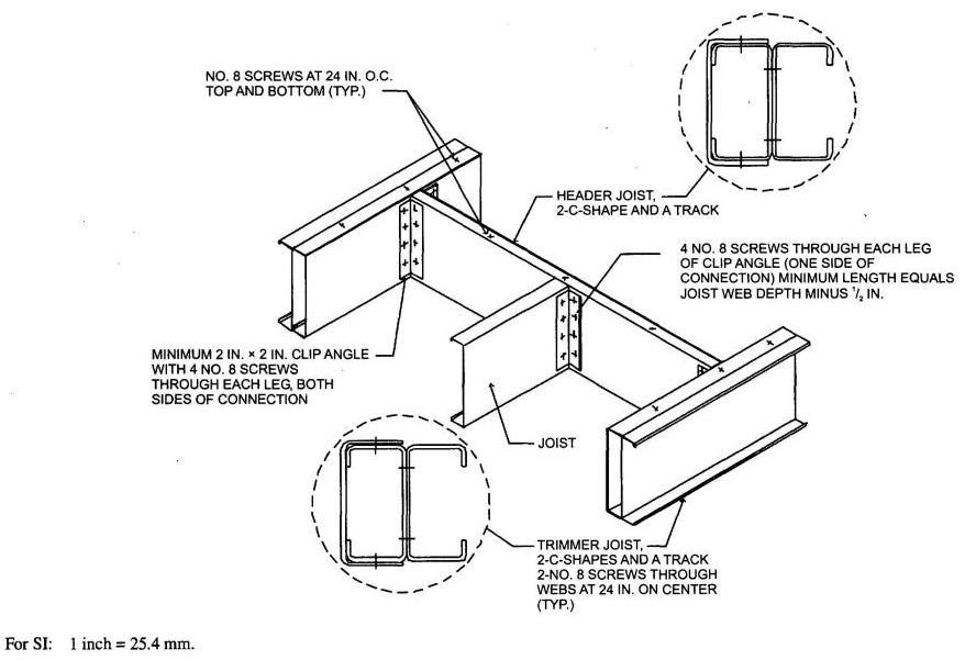
FIGURE R505.3.8(4)
COLD-FORMED STEEL FLOOR CONSTRUCTION: FLOOR HEADER TO TRIMMER CONNECTION—8-FOOT OPENING
R506.1 General. Concrete slab-on-ground floors shall be a minimum 3.5 inches (89 mm) thick (for expansive soils, see Section R403.1.8). The specified compressive strength of concrete shall be as set forth in Section R402.2.
R506.2 Site Preparation. The area within the foundation walls shall have all vegetation, top soil and foreign material removed.
R506.2.1 Fill. Fill material shall be free of vegetation and foreign material. The fill shall be compacted to assure uniform support of the slab, and except where approved, the fill depths shall not exceed 24 inches (610 mm) for clean and or gravel and 8 inches (203 mm) for earth.
R506.2.2 Base. A 4-inch-thick (102 mm) base course consisting of clean graded sand, gravel, crushed stone or crushed blast-furnace slag passing a 2-inch (51 mm) sieve shall be placed on the prepared subgrade when the slab is below grade.
Exception: A base course is not required when the concrete slab is installed on well-drained or sand-gravel mixture soils classified as Group I according to the United Soil Classification System in accordance with Table R405.1.
R506.2.3 Vapor retarder. A 6 mil (0.006 inch; 152 mm) polyethlene or approved vapor retarder with joints lapped not less than 6 inches (152 mm) shall be placed between the concrete floor slab and the base course or the prepared subgrade where no base course exists.
Exception: The vapor retarded may be omitted;
- From detached garages, utility buildings and other unheated accessory structures.
- For unheated storage rooms having an area of less than 70 square feet (6.5 m2) and carports.
- From driveways, walks, patios and other flatwork not likely to be enclosed and heated at a later date.
- Where approved by the building official, based on local site conditions.
R506.2.4 Reinforcement support. Where provided in slab on ground, reinforcement shall be supported to remain in place from the center to upper one third of the slab for the duration of the concrete placement.
| Adopting agency | BSC | SFM | HCD | DSA | OSHPD | CSA | DPH | AGR | DWR | CEC | CA | SL | SLC | ||||||
|---|---|---|---|---|---|---|---|---|---|---|---|---|---|---|---|---|---|---|---|
| 1 | 2 | 1-AC | AC | SS | 1 | 2 | 3 | 4 | |||||||||||
| Adopt entire chapter | |||||||||||||||||||
| Adopt entire chapter as amended (amended sections listed below) | X | X | |||||||||||||||||
| Adopt only those sections that are listed below | |||||||||||||||||||
| Chapter/Section | |||||||||||||||||||
| R601.3 | X | X | |||||||||||||||||
| R601.3.1 | X | X | |||||||||||||||||
| R602.1 | X | X | |||||||||||||||||
| Table R602.10.1.2(2) | X | X | |||||||||||||||||
| R602.10.5.4 | X | X | |||||||||||||||||
| R606.1.1 | X | X | |||||||||||||||||
| R611.1 | X | X | |||||||||||||||||
| R613.1 | X | X | |||||||||||||||||
R601.1 Application. The provisions of this chapter shall control the design and construction of all walls and partitions for all buildings.
R601.2 Requirements. Wall construction shall be capable of accommodating all loads imposed according to Section R301 and of transmitting the resulting loads to the supporting structural elements.
R601.2.1 Compressible floor-covering materials. Compressible floor-covering materials that compress more than 1/32 inch (0.8 mm) when subjected to 50 pounds (23 kg) applied over 1 inch square (645 mm) of material and are greater than 1/8 inch (3 mm) in thickness in the uncompressed state shall not extend beneath walls, partitions or columns, which are fastened to the floor.
R601.3 Vapor retarders. Class I or II vapor retarders are required on the interior side of frame walls in Zones 14 and 16. See Title 24, Part 6, Figure 101-A—California Climate Zones.
Exceptions:
- Basement walls.
- Below grade, portion of any wall.
- Construction where moisture or its freezing will not damage the materials.
R601.3.1 Class III vapor retarders. Class III vapor retarders shall be permitted where any one of the following materials are used. The material options include vented cladding over fiberboard, vented cladding over gypsum, or insulated sheathing with an R value equal to or greater than R-4. If insulated sheathing is used the R-value shall be included as part of the compliance towards Title 24, Part 6 Building Energy Efficiency Standards.
Spray foam with a minimum density of 2 lb/ft3 applied to the interior cavity side of OSB, plywood, fiberboard, insulated sheathing or gypsum is deemed to meet the insulated sheathing requirement where the spray foam R-value meets or exceeds the specified insulated sheathing R-value.
R601.3.2 Material vapor retarder class. The vapor retarder class shall be based on the manufacturer's certified testing or a tested assembly.
The following shall be deemed to meet the class specified:
Class I: Sheet polyethylene, unperforated aluminum foil.
Class II: Kraft-faced fiberglass batts.
Class III: Latex or enamel paint.
R601.3.3 Minimum clear air spaces and vented openings for vented cladding. For the purposes of this section, vented cladding shall include the following minimum clear air spaces. Other openings with the equivalent vent area shall be permitted.
R602.1 Identification. Load-bearing dimension lumber for studs, plates and headers shall be identified by a grade mark of a lumber grading or inspection agency that has been approved by an accreditation body that complies with DOC PS 20. In lieu of a grade mark, a certification of inspection issued by a lumber grading or inspection agency meeting the requirements of this section shall be accepted.
Note: See Section R301.1.1.1 for limited-density owner-built rural dwellings.
R602.1.1 End-jointed lumber. Approved end-jointed lumber identified by a grade mark conforming to Section R602.1 may be used interchangeably with solid-sawn members of the same species and grade.
R602.1.2 Structural glued laminated timbers. Glued laminated timbers shall be manufactured and identified as required in ANSI/AITC A190.1 and ASTM D 3737.
R602.1.3 Structural log members. Stress grading of structural log members of nonrectangular shape, as typically used in log buildings, shall be in accordance with ASTM D 3957. Such structural log members shall be identified by the grade mark of an approved lumber grading or inspection agency. In lieu of a grade mark on the material, a certificate of inspection as to species and grade, issued by a lumber-grading or inspection agency meeting the requirements of this section, shall be permitted to be accepted.
R602.2 Grade. Studs shall be a minimum No. 3, standard or stud grade lumber.
Exception: Bearing studs not supporting floors and nonbearing studs may be utility grade lumber, provided the studs are spaced in accordance with Table R602.3(5).
R602.3 Design and construction. Exterior walls of wood-frame construction shall be designed and constructed in accordance with the provisions of this chapter and Figures R602.3(1) and R602.3.(2) or in accordance with AF&PA's NDS. Components of exterior walls shall be fastened in accordance with Tables R602.3(1) through R602.3(4). Structural wall sheathing shall be fastened directly to structural framing members. Exterior wall coverings shall be capable of resisting the wind pressures listed in Table R301.2(2) adjusted for height and exposure using Table R301.2(3). Wood structural panel
199sheathing used for exterior walls shall conform to the requirements of Table R602.3(3).
Studs shall be continuous from support at the sole plate to a support at the top plate to resist loads perpendicular to the wall. The support shall be a foundation or floor, ceiling or roof diaphragm or shall be designed in accordance with accepted engineering practice.
Exception: Jack studs, trimmer studs and cripple studs at openings in walls that comply with Table R502.5(1) and R502.5(2).
R602.3.1 Stud size, height and spacing. The size, height and spacing of studs shall be in accordance with Table R602.3.(5).
Exceptions:
- Utility grade studs shall not be spaced more than 16 inches (406 mm) on center, shall not support more than a roof and ceiling, and shall not exceed 8 feet (2438 mm) in height for exterior walls and load-bearing walls or 10 feet (3048 mm) for interior nonload-bearing walls.
- Studs more than 10 feet (3048 mm) in height which are in accordance with Table R602.3.1.
R602.3.2 Top plate. Wood stud walls shall be capped with a double top plate installed to provide overlapping at corners and intersections with bearing partitions. End joints in top plates shall be offset at least 24 inches (610 mm).Joints in plates need not occur over studs. Plates shall be not less than 2-inches (51 mm) nominal thickness and have a width at least equal to the width of the studs.
Exception: A single top plate may be installed in stud walls, provided the plate is adequately tied at joints, corners and intersecting walls by a minimum 3-inch-by-6-inch by a 0.036-inch-thick (76 mm by 152 mm by 0.914 mm) galvanized steel plate that is nailed to each wall or segment of wall by six 8d nails on each side, provided the rafters or joists are centered over the studs with a tolerance of no more than 1 inch (25 mm). The top plate may be omitted over lintels that are adequately tied to adjacent wall sections with steel plates or equivalent as previously described.
R602.3.3 Bearing studs. Where joists, trusses or rafters are spaced more than 16 inches (406 mm) on center and the bearing studs below are spaced 24 inches (610 mm) on center, such members shall bear within 5 inches (127 mm) of the studs beneath.
Exceptions:
- The top plates are two 2-inch by 6-inch (38 mm by 140 mm) or two 3-inch by 4-inch (64 mm by 89 mm) members.
- A third top plate is installed.
- Solid blocking equal in size to the studs is installed to reinforce the double top plate.
R602.3.4 Bottom (sole) plate. Studs shall have full bearing on a nominal 2-by (51 mm) or larger plate or sill having a width at least equal to the width of the studs.
R602.4 Interior load-bearing walls. Interior load-bearing walls shall be constructed, framed and fireblocked as specified for exterior walls.
R602.5 Interior nonbearing walls. Interior nonbearing walls shall be permitted to be constructed with 2-inch-by-3-inch (51 mm by 76 mm) studs spaced 24 inches (610 mm) on center or, when not part of a braced wall line, 2-inch-by-4-inch (51 mm by 102 mm) flat studs spaced at 16 inches (406 mm) on center. Interior nonbearing walls shall be capped with at least a single top plate. Interior nonbearing walls shall be fireblocked in accordance with Section R602.8.
R602.6 Drilling and notching–studs. Drilling and notching of studs shall be in accordance with the following:
Exception: Use of approved stud shoes is permitted when they are installed in accordance with the manufacturer's recommendations.
R602.6.1 Drilling and notching of top plate. When piping or ductwork is placed in or partly in an exterior wall or interior load-bearing wall, necessitating cutting, drilling or notching of the top plate by more than 50 percent of its width, a galvanized metal tie not less than 0.054 inch thick (1.37 mm) (16 ga) and 1½ inches (38 mm) wide shall be fastened across and to the plate at each side of the opening with not less than eight 10d (0.148 inch diameter) having a minimum length of 17frac12; inches (38 mm) at each side or equivalent. The metal tie must extend a minimum of 6 inches past the opening. See Figure R602.6.1.
Exception: When the entire side of the wall with the notch or cut is covered by wood structural panel sheathing.
R602.7 Headers. For header spans see Tables R502.5(1) and R502.5(2).
R602.7.1 Wood structural panel box headers. Wood structural panel box headers shall be constructed in accordance with Figure R602.7.2 and Table R602.7.2.
R602.7.2 Nonbearing walls.Load-bearing headers are not required in interior or exterior nonbearing walls. A single flat 2-inch-by-4-inch (51 mm by 102 mm) member may be used as a header in interior or exterior nonbearing walls for openings up to 8 feet (2438 mm) in width if the vertical distance to the parallel nailing surface above is not more than 24 inches (610 mm). For such nonbearing headers, no cripples or blocking are required above the header.
| NOMINAL MATERIAL THICKNESS (inches) | DESCRIPTIONa, b OF FASTENER AND LENGTH (inches) | SPACINGc OF FASTENERS | |
|---|---|---|---|
| Edges (inches) | Intermediate supports (inches) | ||
| For SI: 1 inch = 25.4 mm. | |||
| a. Nail is a general description and may be T-head, modified round head or round head. | |||
| b. Staples shall have a minimum crown width of 7/16-inch on diameter except as noted. | |||
| c. Nails or staples shall be spaced at not more than 6 inches on center at all supports where spans are 48 inches or greater. Nails or staples shall be spaced at not more than 12 inches on center at intermediate supports for floors. | |||
| d. Fasteners shall be placed in a grid pattern throughout the body of the panel. | |||
| e. For 5-ply panels, intermediate nails shall be spaced not more than 12 inches on center each way. | |||
| f. Hardboard underlayment shall conform to ANSI/AHA A135.4. | |||
| Wood structural panels subfloor, roof and wall sheathing to framing and particleboard wall sheathing to framingf | |||
| up to ½ | Staple 15 ga. 1¾ | 4 | 8 |
| 0.097 - 0.099 Nail 2¼ | 3 | 6 | |
| Staple 16 ga. 1¾ | 3 | 6 | |
| 19/32 and 5/8 | 0.113 Nail 2 | 3 | 6 |
| Staple 15 and 16 ga. 2 | 4 | 8 | |
| 0.097 - 0.099 Nail 2¼ | 4 | 8 | |
| 23/32 and ¾ | Staple 14 ga. 2 | 4 | 8 |
| Staple 15 ga. 1¾ | 3 | 6 | |
| 0.097 - 0.099 Nail 2¼ | 4 | 8 | |
| Staple 16 ga. 2 | 4 | 8 | |
| 1 | Staple 14 ga. 2 ¼ | 4 | 8 |
| 0.113 Nail 2¼ | 3 | 6 | |
| Staple 15 ga. 2¼ | 4 | 8 | |
| 0.097 - 0.099 Nail 2½ | 4 | 8 | |
| NOMINAL MATERIAL THICKNESS (inches) | DESCRIPTIONa, b OF FASTENER AND LENGTH (inches) | SPACINGcOF FASTENERS | |
| Edges (inches) | Body of paneld (inches) | ||
| Floor underlayment; plywood-hardboard-particleboardf | |||
| Plywood | |||
| ¼ and 5/16 | 1 ¼ ring or screw shank nail—minimum 12½ ga. (0.099″) shank diameter | 3 | 6 |
| Staple 18 ga. 7/8, 3/16 crown width | 2 | 5 | |
| 11/32, 3/8, 15/32, and ½ | 1 ¼ ring or screw shank nail—minimum 12½ ga. (0.099″) shank diameter | 6 | 8c |
| 19/32, 5/8, 23/32 and 3/4 | 1 ½ ring or screw shank nail—minimum 12½ ga. (0.099″) shank diameter | 6 | 8 |
| Staple 16 ga. 1½ | 6 | 8 | |
| Hardboardf | |||
| 0.200 | 1½ long ring-grooved underlayment nail | 6 | 6 |
| 4d cement-coated sinker nail | 6 | 6 | |
| Staple 18 ga., 7/8 long (plastic coated) | 3 | 6 | |
| Particleboard | |||
| ¼ | 4d ring-grooved underlayment nail | 3 | 6 |
| Staple 18 ga., 7/8 long, 3/16 crown | 3 | 6 | |
| 3/8 | 6d ring-grooved underlayment nail | 6 | 10 |
| Staple 16 ga., 11/8 long, 3/8 crown | 3 | 6 | |
| ½, 5/8 | 6d ring-grooved underlayment nail | 6 | 10 |
| Staple 16 ga., 15/8 long, 3/8 crown | 3 | 6 | |
| MINIMUM NAIL | MINIMUM WOOD STRUCTURAL PANEL SPAN RATING | MINIMUM NOMINAL PANEL THICKNESS (inches) | MAXIMUM WALL STUD SPACING (inches) | PANEL NAIL SPACING | MAXIMUM WIND SPEED (mph) | ||||
|---|---|---|---|---|---|---|---|---|---|
| Size | Penetration (inches) | Edges (inches o.c.) | Field (inches o.c.) | Wind exposure category | |||||
| B | C | D | |||||||
| For SI: 1 inch = 25.4 mm, 1 mile per hour = 0.447 m/s. | |||||||||
| a. Panel strength axis parallel or perpendicular to supports. Three-ply plywood sheathing with studs spaced more than 16 inches on center shall be applied with panel strength axis perpendicular to supports. | |||||||||
| b. Table is based on wind pressures acting toward and away from building surfaces per Section R301.2. Lateral bracing requirements shall be in accordance with Section R602.10. | |||||||||
| c. Wood Structural Panels with span ratings of Wall-16 or Wall-24 shall be permitted as an alternate to panels with a 24/0 span rating. Plywood siding rated 16 oc or 24 oc shall be permitted as an alternate to panels with a 24/16 span rating. Wall-16 and Plywood siding 16 oc shall be used with studs spaced a maximum of 16 inches on center. | |||||||||
| 6d Common (2.0″ × 0.113″) | 1.5 | 24/0 | 3/8 | 16 | 6 | 12 | 110 | 90 | 85 |
| 8d Common (2.5″ × 0.131″) | 1.75 | 24/16 | 7/16 | 16 | 6 | 12 | 130 | 110 | 105 |
| 24 | 6 | 12 | 110 | 90 | 85 | ||||
| THICKNESS (inch) | GRADE | STUD SPACING (inches) | |
|---|---|---|---|
| When siding is nailed to studs | When siding is nailed to sheathing | ||
| For SI: 1 inch = 25.4 mm. | |||
| a. Wall sheathing not exposed to the weather. If the panels are applied horizontally, the end joints of the panel shall be offset so that four panels corners will not meet. All panel edges must be supported. Leave a 1/16-inch gap between panels and nail no closer than 3/8 inch from panel edges. | |||
| 3/8 | M—1 Exterior glue | 16 | — |
| ½ | M—2 Exterior glue | 16 | 16 |
| STUD SIZE (inches) | BEARING WALLS | NONBEARING WALLS | |||||
|---|---|---|---|---|---|---|---|
| Laterally unsupported stud heighta (feet) | Maximum spacing when supporting a roof-ceiling assembly or a habitable attic assembly, only (inches) | Maximum spacing when supporting one floor, plus a roof-ceiling assembly or a habitable attic assembly (inches) | Maximum spacing when supporting two floors, plus a roof-ceiling assembly or a habitable attic assembly (inches) | Maximum spacing when supporting one floor heighta(feet) | Laterally unsupported stud heighta (feet) | Maximum spacing (inches) | |
| For SI: 1 inch = 25.4 mm, 1 foot = 304.8 mm, 1 square foot = 0.093 m2. | |||||||
| a. Listed heights are distances between points of lateral support placed perpendicular to the plane of the wall. Increases in unsupported height are permitted where justified by analysis. | |||||||
| b. Shall not be used in exterior walls. | |||||||
| c. A habitable attic assembly supported by 2 × 4 studs is limited to a roof span of 32 feet. Where the roof span exceeds 32 feet, the wall studs shall be increased to 2 × 6 or the studs shall be designed in accordance with accepted engineering practice. | |||||||
 |
 |
 |
 |
||||
| 2 × 3b | — | — | — | — | — | 10 | 16 |
| 2 × 4 | 10 | 24c | 16c | — | 24 | 14 | 24 |
| 3 × 4 | 10 | 24 | 24 | 16 | 24 | 14 | 24 |
| 2 × 5 | 10 | 24 | 24 | — | 24 | 16 | 24 |
| 2 × 6 | 10 | 24 | 24 | 16 | 24 | 20 | 24 |
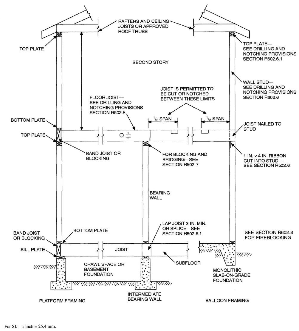
FIGURE R602.3(1)
TYPICAL WALL, FLOOR AND ROOF FRAMING
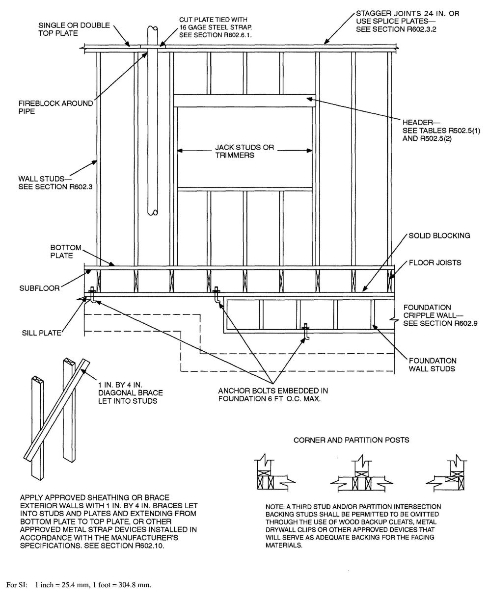
FIGURE R602.3(2)
FRAMING DETAILS
| HEIGHT (feet) | ON-CENTER SPACING (inches) | |||
|---|---|---|---|---|
| 24 | 16 | 12 | 8 | |
| Supporting a roof only | ||||
| For SI: 1 inch = 25.4 mm, 1 foot = 304.8 mm, 1 pound per square foot = 0.0479kPa, 1 pound per square inch = 6.895 kPa, 1 mile per hour = 0.447 m/s. | ||||
| a. Design required. | ||||
| b. Applicability of this table assumes the following: Snow load not exceeding 25 psf, fb not less than 1310 psi determined by multiplying the AF&PA NDS tabular base design value by the repetitive use factor, and by the size factor for all species except southern pine, E not less than 1.6 × 10⁶ psi, tributary dimensions for floors and roofs not exceeding 6 feet, maximum span for floors and roof not exceeding 12 feet, eaves not over 2 feet in dimension and exterior sheathing. Where the conditions are not within these parameters, design is required. | ||||
| c. Utility, standard, stud and No. 3 grade lumber of any species are not permitted. | ||||
| >10 | 2 × 4 | 2 × 4 | 2 × 4 | 2 × 4 |
| 12 | 2 × 6 | 2 × 4 | 2 × 4 | 2 × 4 |
| 14 | 2 × 6 | 2 × 6 | 2 × 6 | 2 × 4 |
| 16 | 2 × 6 | 2 × 6 | 2 × 6 | 2 × 4 |
| 18 | NAa | 2 × 6 | 2 × 6 | 2 × 6 |
| 20 | NAa | NAa | 2 × 6 | 2 × 6 |
| 24 | NAa | NAa | NAa | 2 × 6 |
| Supporting one floor and a roof | ||||
| >10 | 2 × 6 | 2 × 4 | 2 × 4 | 2 × 4 |
| 12 | 2 × 6 | 2 × 6 | 2 × 6 | 2 × 4 |
| 14 | 2 × 6 | 2 × 6 | 2 × 6 | 2 × 6 |
| 16 | NAa | 2 × 6 | 2 × 6 | 2 × 6 |
| 18 | NAa | 2 × 6 | 2 × 6 | 2 × 6 |
| 20 | NAa | NAa | 2 × 6 | 2 × 6 |
| 24 | NAa | NAa | NAa | 2 × 6 |
| Supporting two floors and a roof | ||||
| >10 | 2 × 6 | 2 × 6 | 2 × 4 | 2 × 4 |
| 12 | 2 × 6 | 2 × 6 | 2 × 6 | 2 × 6 |
| 14 | 2 × 6 | 2 × 6 | 2 × 6 | 2 × 6 |
| 16 | NAa | NAa | 2 × 6 | 2 × 6 |
| 18 | NAa | NAa | 2 × 6 | 2 × 6 |
| 20 | NAa | NAa | NAa | 2 × 6 |
| 22 | NAa | NAa | NAa | NAa |
| 24 | NAa | NAa | NAa | NAa |
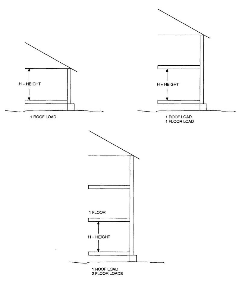
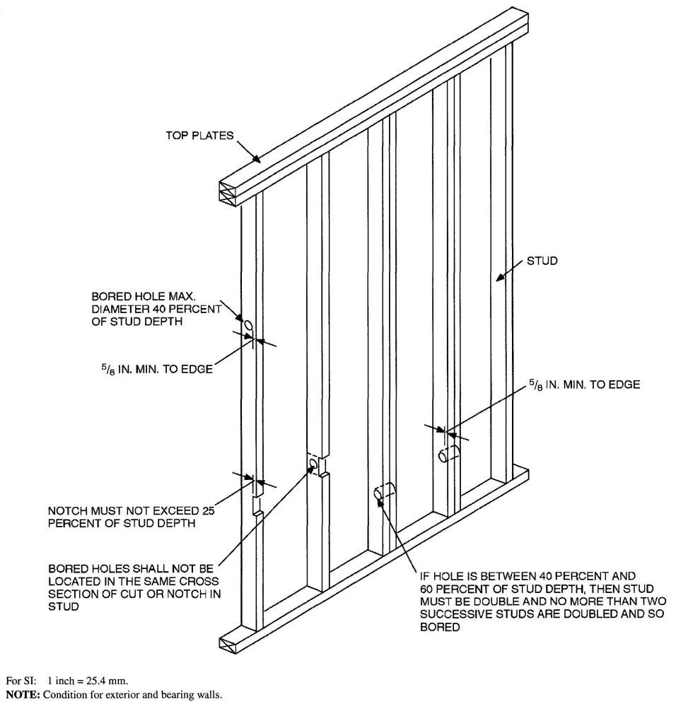
FIGURE R602.6(1)
NOTCHING AND BORED HOLE LIMITATIONS FOR EXTERIOR WALLS AND BEARING WALLS
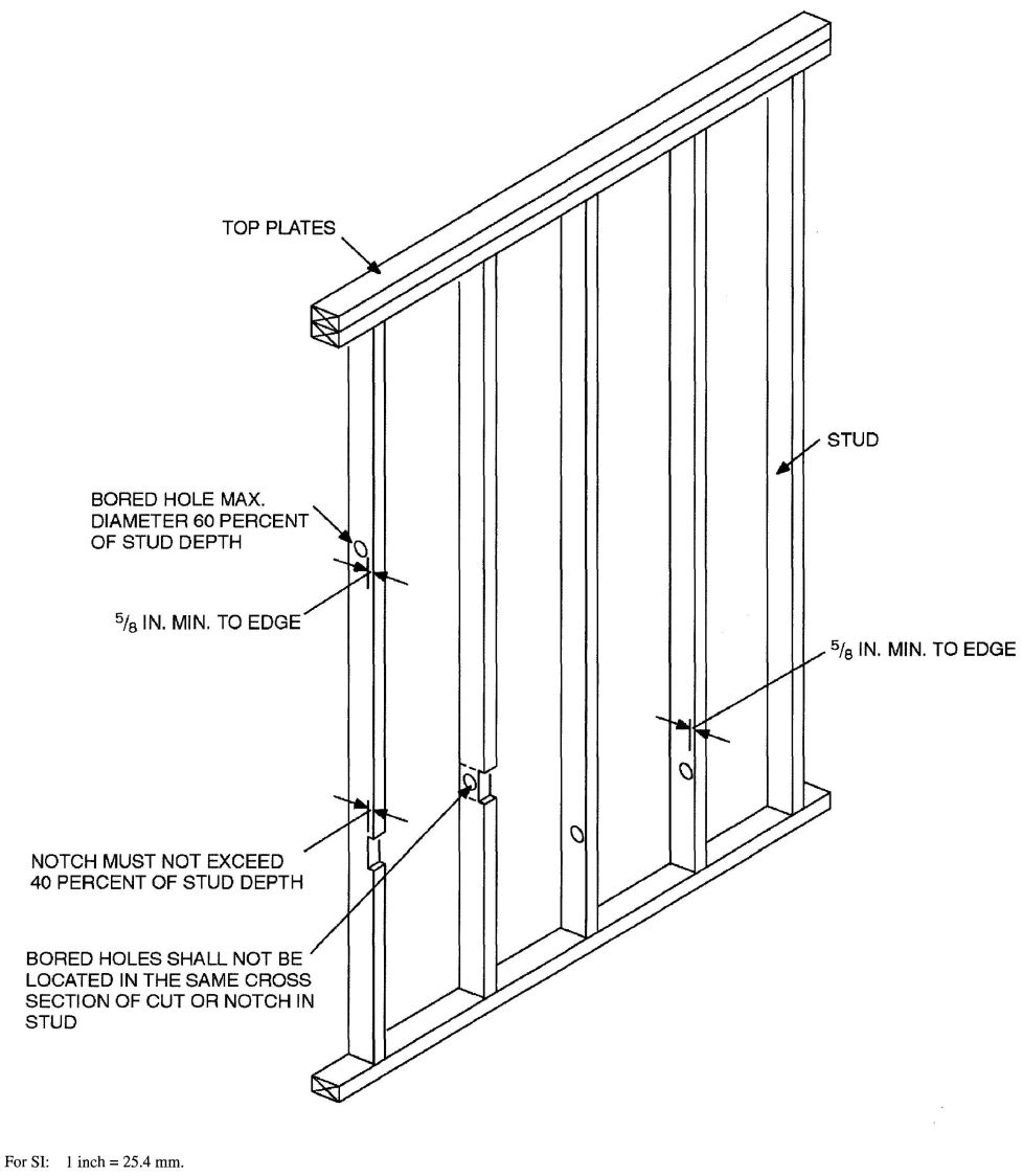
FIGURE R602.6(2)
NOTCHING AND BORED HOLE LIMITATIONS FOR INTERIOR NONBEARING WALLS
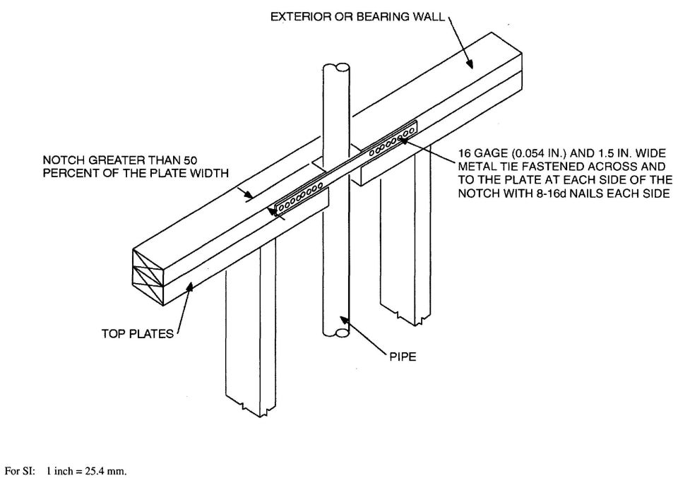
FIGURE R602.6.1
TOP PLATE FRAMING TO ACCOMMODATE PIPING
| HEADER CONSTRUCTIONb | HEADER DEPTH (inches) | HOUSE DEPTH (feet) | ||||
|---|---|---|---|---|---|---|
| 24 | 26 | 28 | 30 | 32 | ||
| For SI: 1 inch = 25.4 mm, 1 foot = 304.8 mm. | ||||||
| a. Spans are based on single story with clear-span trussed roof or two-story with floor and roof supported by interior-bearing walk. | ||||||
| b. See Figure R602.7.2 for construction details. | ||||||
| Wood structural panel—one side | 9 | 4 | 4 | 3 | 3 | — |
| 15 | 5 | 5 | 4 | 3 | 3 | |
| Wood structural panel—both sides | 9 | 7 | 5 | 5 | 4 | 3 |
| 15 | 8 | 8 | 7 | 7 | 6 | |
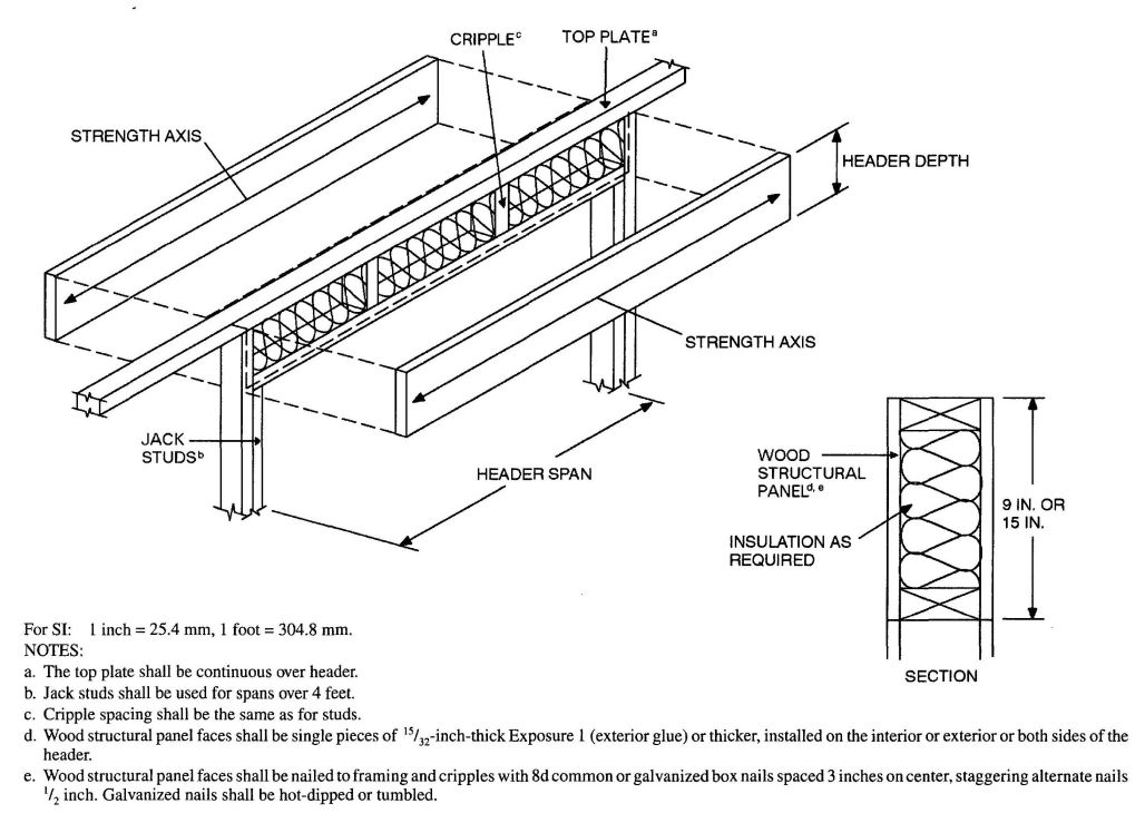
FIGURE R602.7.2
TYPICAL WOOD STRUCTURAL PANEL BOX HEADER CONSTRUCTION
R602.8 Fireblocking required. Fireblocking shall be provided in accordance with Section R302.11.
R602.9 Cripple walls. Foundation cripple walls shall be framed of studs not smaller than the studding above. When exceeding 4 feet (1219 mm) in height, such walls shall be framed of studs having the size required for an additional story.
Cripple walls with a stud height less than 14 inches (356 mm) shall be sheathed on at least one side with a wood structural panel that is fastened to both the top and bottom plates in accordance with Table R602.3(1), or the cripple walls shall be constructed of solid blocking. Cripple walls shall be supported on continuous foundations.
R602.10 Wall bracing. Buildings shall be braced in accordance with this section. Where a building, or portion thereof, does not comply with one or more of the bracing requirements in this section, those portions shall be designed and constructed in accordance with Section R301.1.
Exception: Detached one- and two-family dwellings located in Seismic Design Category C are exempt from the seismic bracing requirements of this section. Wind speed provisions for bracing shall be applicable to detached one-and two-family dwellings.
R602.10.1 Braced wall lines. Braced wall lines shall be provided in accordance with this section. The length of a braced wall line shall be measured as the distance between the ends of the wall line. The end of a braced wall line shall be considered to be either:
The end of the braced wall line shall be chosen such that the maximum length results.
R602.10.1.1 Braced wall panels. Braced wall panels shall be constructed in accordance with the intermittent bracing methods specified in Section R602.10.2, or the continuous sheathing methods specified in Sections R602.10.4 and R602.10.5. Mixing of bracing method shall be permitted as follows:
R602.10.1.2 Length of bracing. The length of bracing along each braced wall line shall be the greater of that required by the design wind speed and braced wall line spacing in accordance with Table R602.10.1.2(1) as adjusted by the factors in the footnotes or the Seismic Design Category and braced wall line length in accordance with Table R602.10.1.2(2) as adjusted by the factors in Table R602.10.1.2(3) or braced wall panel location requirements of Section R602.10.1.4. Only walls that are parallel to the braced wall line shall be counted toward the bracing requirement of that line, except angled walls shall be counted in accordance with Section R602.10.1.3. In no case shall the minimum total length of bracing in a braced wall line, after all adjustments have been taken, be less than 48 inches (1219 mm) total.
R602.10.1.2.1 Braced wall panel uplift load path. Braced wall panels located at exterior walls that support roof rafters or trusses (including stories below top story) shall have the framing members connected in accordance with one of the following:
R602.10.1.3 Angled corners. At corners, braced wall lines shall be permitted to angle out of plane up to 45 degrees with a maximum diagonal length of 8 feet (2438 mm). When determining the length of bracing required, the length of each braced wall line shall be determined as shown in Figure R602.10.1.3. The placement of bracing for the braced wall line shall begin at the point where the braced wall line, which contains the angled wall adjoins the adjacent braced wall line (Point A as shown in Figure R602.10.1.3). Where an angled corner is constructed at an angle equal to 45 degrees (0.79 rad) and the diagonal length is no more than 8 feet (2438 mm), the angled wall may be considered as part of either of the adjoining braced wall lines, but not both. Where the diagonal length is greater than 8 feet (2438 mm), it shall be considered its own braced wall line and be braced in accordance with Section R602.10.1 and methods in Section R602.10.2.
R602.10.1.4 Braced wall panel location. Braced wall panels shall be located in accordance with Figure R602.10.1.4(1). Braced wall panels shall be located not more than 25 feet (7620 mm) on center and shall be permitted to begin no more than 12.5 feet (3810 mm) from the end of a braced wall line in accordance with Section R602.10.1 and Figure R602.10.1.4(2). The total combined distance from each end of a braced wall line to the outermost braced wall panel or panels in the line shall not exceed 12.5 feet (3810 mm). Braced wall panels may be offset out-of-plane up to 4 feet (1219 mm) from the designated braced wall line provided that the total out-to-out offset of braced wall panels in a braced wall line is not more than 8 feet (2438 mm) in accordance with Figures R602.10.1.1(3) and R602.10.1.4(4). All braced wall panels within a braced wall line shall be permitted to be offset from the designated braced wall line.
R602.10.1.4.1 Braced wall panel location in Seismic Design Categories D0, D1 and D2. Braced wall lines at exterior walls shall have a braced wall panel located at each end of the braced wall line.
Exception: For braced wall panel construction Method WSP of Section R602.10.2, the braced wall panel shall be permitted to begin no more than 8 feet (2438 mm) from each end of the braced wall line provided one of the following is satisfied in accordance with Figure R602.10.1.4.1:
| ADJUSTMENT BASED ON: | MULTIPLY LENGTH OF BRACING PER WALL LINE BY: | APPLIES TO: | ||
|---|---|---|---|---|
| For SI: 1 foot = 304.8 mm, 1 pound per square foot = 47.89 Pa. | ||||
| a. The total length of bracing required for a given wall line is the product of all applicable adjustment factors. | ||||
| b. Linear interpolation shall be permitted. | ||||
| c. Braced wall line spacing and adjustment to bracing length in SDC D0, D1, and D2 shall comply with Section R602.10.1.5. | ||||
| Story heightb (Section R301.3) | ≤10 ft | 1.0 | All bracing methods - Sections R602.10.2, R602.10.4 and R602.1 0.5 | |
| > 10 ≤ 12 ft | 1.2 | |||
| Braced wall line spacing townhouses in SDC A-Cb,c | ≤ 35 ft | 1.0 | ||
| > 35 ≤ 50 ft | 1.43 | |||
| Wall dead load | > 8 ≤ 15 psf | 1.0 | ||
| ≤ 8 psf | 0.85 | |||
| Roof/ceiling dead load for wall supportingb | roof only or roof plus one story | ≤ 15 psf | 1.0 | |
| roof only | < 15 psf ≤ 25 psf | 1.1 | ||
| roof plus one story | < 15 psf ≤ 25 psf | 1.2 | ||
| Walls with stone or masonry veneer in SDC C-D2 | See Section R703.7 | |||
| Cripple walls | See Section R602.10.9 | |||
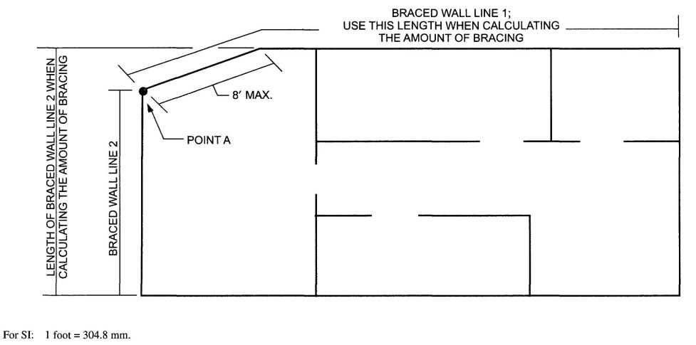
FIGURE R602.10.1.3
ANGLED CORNERS
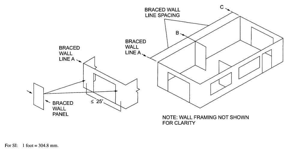
FIGURE R602.10.1.4(1)
BRACED WALL PANELS AND BRACED WALL LINES
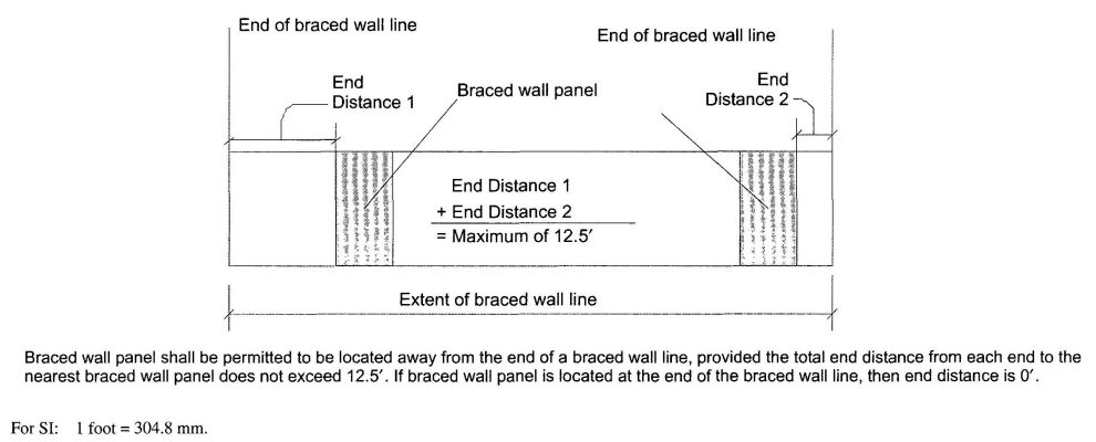
FIGURE R602.10.1.4(2)
BRACED WALL PANEL END DISTANCE REQUIREMENTS (SDC A, B AND C)
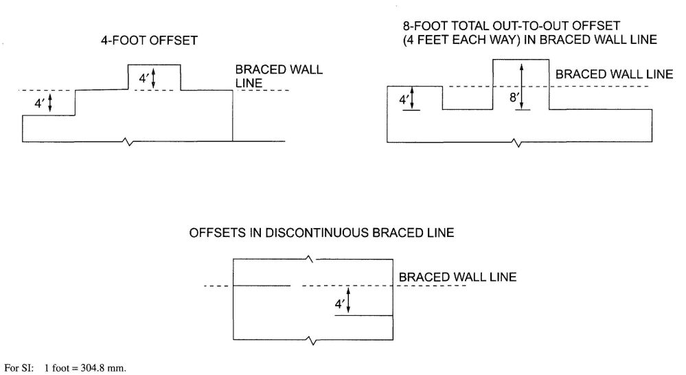
FIGURE R602.10.1.4(3)
OFFSETS PERMITTED FOR BRACED WALL LINES
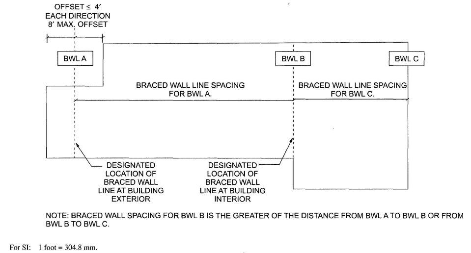
FIGURE R602.10.1.4(4)
BRACED WALL LINE SPACING
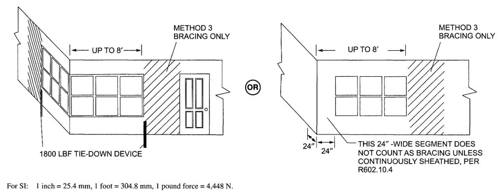
FIGURE R602.10.1.4.1
BRACED WALL PANELS AT ENDS OF BRACED WALL LINES IN SEISMIC DESIGN CATEGORIES D0 D1 AND D2
| BRACED WALL LINE SPACING (feet) | MULTIPLY BRACING LENGTH IN TABLE R602.10.1.2(2) BY: |
|---|---|
| For SI: 1 foot = 304.8 mm. | |
| a. Linear interpolation is permitted. | |
| b. When a braced wall line has a parallel braced wall line on both sides, the larger adjustment factor shall be used. | |
| 25 | 1.0 |
| 30 | 1.2 |
| 35 | 1.4 |
R602.10.1.5 Braced wall line spacing for Seismic Design Categories D0, D1 and D2. Spacing between braced wall lines in each story shall not exceed 25 feet (7620 mm) on center in both the longitudinal and transverse directions.
Exception: In one-and two-story buildings, spacing between two adjacent braced wall lines shall not exceed 35 feet (10 668 mm) on center in order to accommodate one single room not exceeding 900 square feet (84 m2) in each dwelling unit. Spacing between all other braced wall lines shall not exceed 25 feet (7620 mm). A spacing of 35 feet (10 668 mm) or less shall be permitted between braced wall lines where the length of wall bracing required by Table R602.10.1.2(2) is multiplied by the appropriate adjustment factor from Table R602.10.1.5, the length-to-width ratio for the floor/roof diaphragm does not exceed 3:1, and the top plate lap splice face nailing is twelve 16d nails on each side of the splice.
R602.10.2 Intermittent braced wall panel construction methods. The construction of intermittent braced wall panels shall be in accordance with one of the methods listed in Table R602.10.2.
R602.10.2.1 Intermittent braced wall panel interior finish material. Intermittent braced wall panels shall have gypsum wall board installed on the side of the wall opposite the bracing material. Gypsum wall board shall be not less than ½ inch (12.7 mm) in thickness and be fastened in accordance with Table R702.3.5 for interior gypsum wall board.
Exceptions:
- Wall panels that are braced in accordance with Methods GB, ABW, PFG and PFH.
- When an approved interior finish material with an in-plane shear resistance equivalent to gypsum board is installed.
- For Methods DWB, WSP, SFB, PBS, PCP and HPS, omitting gypsum wall board is permitted provided the length of bracing in Tables R602.10.1.2(1) and R602.10.1.2(2) is multiplied by a factor of 1.5.
R602.10.2.2 Adhesive attachment of sheathing in Seismic Design Categories C, D0, D1 and D2. Adhesive attachment of wall sheathing shall not be permitted in Seismic Design Categories C, D0, D1 and D2.
R602.10.3 Minimum length of braced panels. For Methods DWB, WSP, SFB, PBS, PCP and HPS, each braced wall panel shall be at least 48 inches (1219 mm) in length, covering a minimum of three stud spaces where studs are spaced 16 inches (406 mm) on center and covering a minimum of two stud spaces where studs are spaced 24 inches (610 mm) on center. For Method GB, each braced wall panel and shall be at least 96 inches (2438 mm) in length where applied to one face of a braced wall panel and at least 48 inches (1219 mm) where applied to both faces. For Methods DWB, WSP, SFB, PBS, PCP and HPS, for purposes of computing the length of panel bracing required in Tables R602.10.1.2(1) and R602.10.1.2(2), the effective length of the braced wall panel shall be equal to the actual length of the panel. When Method GB panels are applied to only one face of a braced wall panel, bracing lengths required in Tables R602.10.1.2(1) and R602.10.1.2(2) for Method GB shall be doubled.
Exceptions:
- Lengths of braced wall panels for continuous sheathing methods shall be in accordance with Table R602.10.4.2.
- Lengths of Method ABW panels shall be in accordance with Sections R602.10.3.2.
- Length of Methods PFH and PFG panels shall be in accordance with Section R602.10.3.3 and R602.10.3.4 respectively.
- For Methods DWB, WSP, SFB, PBS, PCP and HPS in Seismic Design Categories A, B, and C: Panels between 36 inches (914 mm) and 48 inches (1219 mm) in length shall be permitted to count towards the required length of bracing in Tables R602.10.1.2(1) and R602.10.1.2(2), and the effective contribution shall comply with Table R602.10.3.
R602.10.3.1 Adjustment of length of braced panels. When story height (H), measured in feet, exceeds 10 feet (3048 mm), in accordance with Section R301.3, the minimum length of braced wall panels specified in Section R602.10.3 shall be increased by a factor H/10. See Table R602.10.3.1. Interpolation is permitted.
R602.10.3.2 Method ABW: Alternate braced wall panels. Method ABW braced wall panels constructed in accordance with one of the following provisions shall be permitted to replace each 4 feet (1219 mm) of braced wall panel as required by Section R602.10.3. The maximum height and minimum length and hold-down force of each panel shall be in accordance with Table R602.10.3.2:
| METHOD | MATERIAL | MINIMUM THICKNESS | FIGURE | CONNECTION CRITERIA |
|---|---|---|---|---|
| LIB | Let-in-bracing | 1 × 4 wood or approved metal straps at 45° to 60° angles for maximum 16″ stud spacing | 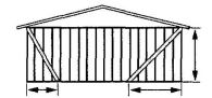 |
Wood: 2-8d nails per stud including top and bottom plate metal: per manufacturer |
| DWB | Diagonal wood boards | ¾″ (1″ nominal) for maximum 24″ stud spacing | 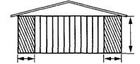 |
2-8d (2½″ × 0.113″) nails or 2 staples, 1¾″ per stud |
| WSP | Wood structural panel (see Section R604) | 3/8″ | 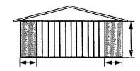 |
For exterior sheathing see Table R602.3(3) For interior sheathing see Table R602.3(1) |
| SFB | Structural fiberboard sheathing | ½″ or 25/32″ for maximum 16″ stud spacing |  |
½″ galvanized roofing nails or 8d common (2 ½″ × 0.131) nails at 3″ spacing (panel edges) at 6″ spacing (intermediate supports) |
| GB | Gypsum board | ½″ |  |
Nails or screws at 7″ spacing at panel edges including top and bottom plates; for all braced wall panel locations for exterior sheathing nail or screw size, see Table R602.3(1); for interior gypsum board nail or screw size, see Table R702.3.5 |
| PBS | Particleboard sheathing (see Section R605) | 3/8″ or ½″ for maximum 16″ stud spacing |  |
1½″ galvanized roofing nails or 8d common (2 ½″ × 0.131) nails at 3″ spacing (panel edges) at 6 spacing (intermediate supports) |
| PCP | Portland cement plaster | See Section R703.6 For maximum 16″ stud spacing |  |
1 ½″, 11 gage, 7/16″ head nails at 6″ spacing or 7/8″, 16 gage staples at 6″ spacing |
| HPS | Hardboard panel siding | 7/16″ For maximum 16″ stud spacing |  |
0.092″ dia., 0.225″ head nails with length to accommodate 1 ½″ penetration into studs at 4″ spacing (panel edges), at 8″ spacing (intermediate supports) |
| ABW | Alternate braced wall | See Section R602.10.3.2 |  |
See Section R602.10.3.2 |
| PFH | Intermittent portal frame | See Section R602.10.3.3 |  |
See Section R602.10.3.3 |
| PFG | Intermittent portal frame at garage | See Section R602.10.3.4 |  |
See Section R602.10.3.4 |
| ACTUAL LENGTH OF BRACED WALL PANEL (inches) | EFFECTIVE LENGTH OF BRACED WALL PANEL (inches) | ||
|---|---|---|---|
| 8-foot Wall Height | 9-foot Wall Height | 10-foot Wall Height | |
| For SI: 1 inch = 25.4 mm, 1 foot = 304.8 mm. | |||
| a. Interpolation shall be permitted. | |||
| 48 | 48 | 48 | 48 |
| 42 | 36 | 36 | N/A |
| 36 | 27 | N/A | N/A |
| SEISMIC DESIGN CATEGORY AND WIND SPEED | BRACING METHOD | HEIGHT OF BRACED WALL PANEL | ||||
|---|---|---|---|---|---|---|
| 8 ft | 9 ft | 10 ft | 11 ft | 12 ft | ||
| For SI: 1 inch = 25.4 mm, 1 foot = 304.8 mm. | ||||||
| SDC A, B, C, D0, D1 and D2 Wind speed < 110 mph | DWB, WSP, SFB, PBS, PCP, HPS and Method GB when double sided | 4′; - 0″ | 4′; - 0″ | 4′; - 0″ | 4′; - 5″ | 4′; - 10″ |
| Method GB, single sided | 8′; - 0″ | 8′; - 0″ | 8′; - 0″ | 8′; - 10″ | 9′; - 8″ | |
| SEISMIC DESIGN CATEGORY AND WIND SPEED | HEIGHT OF BRACED WALL PANEL | |||||
|---|---|---|---|---|---|---|
| 8 ft | 9 ft | 10 ft | 11 ft | 12 ft | ||
| For SI: 1 inch = 25.4 mm, 1 foot = 305 mm, 1 pound = 4.448 N. | ||||||
| a. NP = Not Permitted. Maximum height of 10 feet. | ||||||
| SDC A, B and C Wind speed < 110 mph | Minimum sheathed length | 2′; - 4″ | 2′; - 8″ | 2′; - 10″ | 3′; - 2″ | 3′; - 6″ |
| R602.10.3.2, item 1 hold-down force (lb) | 1800 | 1800 | 1800 | 2000 | 2200 | |
| R602.10.3.2, item 2 hold-down force (lb) | 3000 | 3000 | 3000 | 3300 | 3600 | |
| SDC D0, D1 and D2 Wind speed < 110 mph | Minimum sheathed length | 2′; - 8″ | 2′; - 8″ | 2′; - 10″ | NPa | NPa |
| R602.10.3.2, item 1 hold-down force (lb) | 1800 | 1800 | 1800 | NPa | NPa | |
| R602.10.3.2, item 2 hold-down force (lb) | 3000 | 3000 | 3000 | NPa | NPa | |
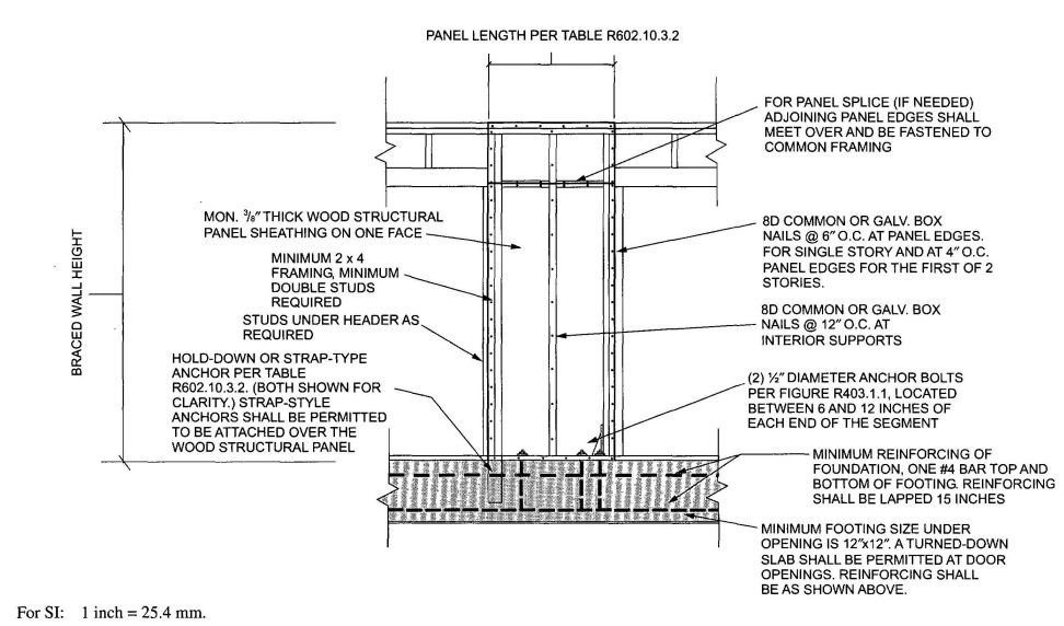
FIGURE R602.10.3.2
ALTERNATE BRACED WALL PANEL
R602.10.3.3 Method PFH: Portal frame with hold-downs. Method PFH braced wall panels constructed in accordance with one of the following provisions are also permitted to replace each 4 feet (1219 mm) of braced wall panel as required by Section R602.10.3 for use adjacent to a window or door opening with a full-length header:
R602.10.3.4 Method PFG: at garage door openings in Seismic Design Categories A, B and C. Where supporting a roof or one story and a roof, alternate braced wall panels constructed in accordance with the following provisions are permitted on either side of garage door openings. For the purpose of calculating wall bracing amounts to satisfy the minimum requirements of Table R602.10.1.2(1), the length of the alternate braced wall panel shall be multiplied by a factor of 1.5.
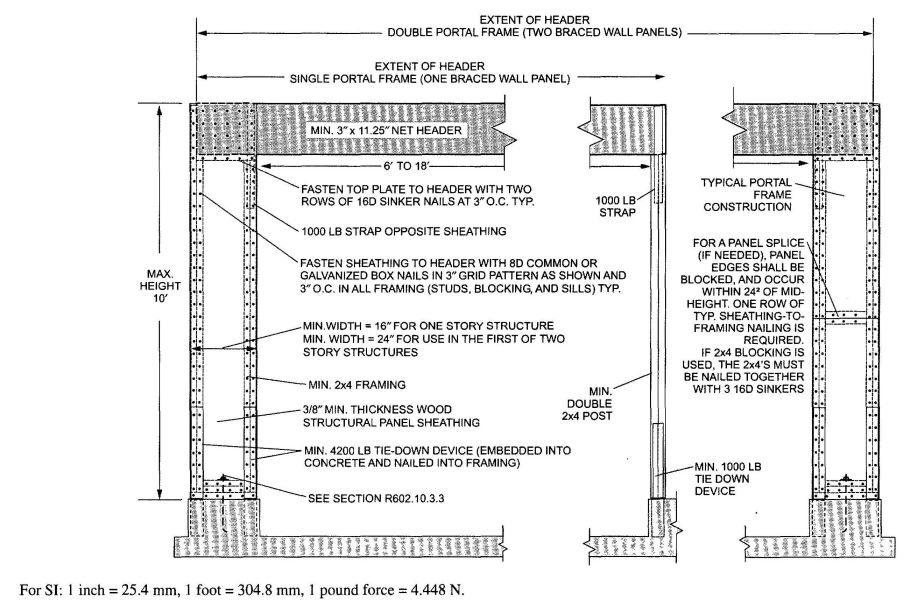
R602.10.4 Continuous sheathing. Braced wall lines with continuous sheathing shall be constructed in accordance with this section. All braced wall lines along exterior walls on the same story shall be continuously sheathed.
Exception: Within Seismic Design Categories A, B and C or in regions where the basic wind speed is less than or equal to 100 mph (45 m/s), other bracing methods prescribed by this code shall be permitted on other braced wall lines on the same story level or on any braced wall line on different story levels of the building.
R602.10.4.1 Continuous sheathing braced wall panels. Continuous sheathing methods require structural panel sheathing to be used on all sheathable surfaces on one side of a braced wall line including areas above and below opening and gable end walls. Braced wall panels shall be constructed in accordance with one of the methods listed in Table R602.10.4.1. Different bracing methods, other than those listed in Table R602.10.4.1, shall not be permitted along a braced wall line with continuous sheathing.
R602.10.4.1.1 Continuous portal frame. Continuous portal frame braced wall panels shall be constructed in accordance with Figure R602.10.4.1.1. The number of continuous portal frame panels in a single braced wall line shall not exceed four. For purposes of resisting wind pressures acting perpendicular to the wall, the requirements of Figure R602.10.4.1.1 and Table R602.10.4.1.1 shall be met. There shall be a maximum of two braced wall segments per header and header length shall not exceed 22 feet (6706 mm ). Tension straps shall be installed in accordance with the manufacturer’s recommendations.
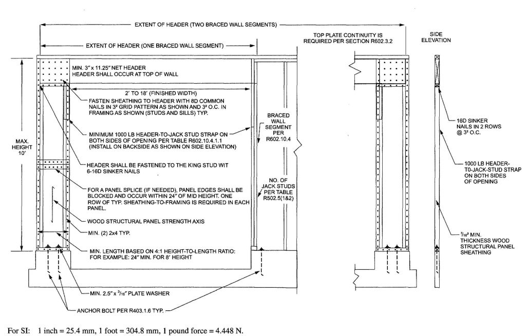
FIGURE R602.10.3.4
METHOD PFG PORTAL FRAME AT GARAGE DOOR OPENINGS IN SEISMIC DESIGN CATEGORIES A, B AND C
| METHOD | MATERIAL | MINIMUM THICKNESS | FIGURE | CONNECTION CRITERIA |
|---|---|---|---|---|
| For SI: 1 inch = 25.4 mm, 1 pound per square foot = 47.89 Pa. | ||||
| a. Applies to one wall of a garage only. | ||||
| b. Roof covering dead loads shall be 3 psf or less. | ||||
| CS-WSP | Wood structural panel | 3/8″ | 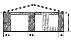 |
6d common (2″ × 0.113″) nails at 6″ spacing (panel edges) and at 12″ spacing (intermediate supports) or 16 ga. × 1¾ staples at 3″ spacing (panel edges) and 6″ spacing (intermediate supports) |
| CS-G | Wood structural panel adjacent to garage openings and supporting roof load onlya,b | 3/8″ | 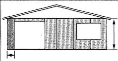 |
See Method CS-WSP |
| CS-PF | Continuous portal frame | See Section R602.10.4.1.1 | 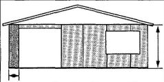 |
See Section R602.10.4.1.1 |
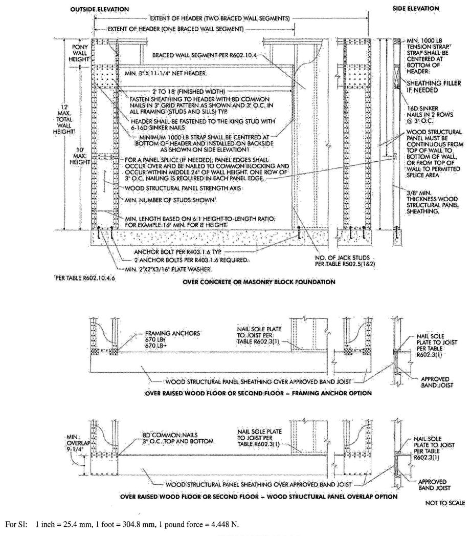
FIGURE R602.10.4.1.1
METHOD CS-PF: CONTINUOUS PORTAL FRAME PANEL CONSTRUCTION
| MINIMUM WALL STUD FRAMING NOMINAL SIZE AND GRADE | MAXIMUM PONY WALL HEIGHT (feet) | MAXIMUM TOTAL WALL HEIGHT (feet) | MAXIMUM OPENING WIDTH (feet) | BASIC WIND SPEED (mph) | |||||
|---|---|---|---|---|---|---|---|---|---|
| 85 | 90 | 100 | 85 | 90 | 100 | ||||
| Exposure B | Exposure C | ||||||||
| Tension strap capacity required (lbf)a, b | |||||||||
| For SI: 1 inch = 25.4 mm, 1 foot = 304.8 mm, 1 pound force = 4.448 N. | |||||||||
| a. DR = design required. | |||||||||
| b. Strap shall be installed in accordance with manufacturer’s recommendations. | |||||||||
| 2 × 4 No. 2 Grade | |||||||||
| 0 | 10 | 18 | 1000 | 1000 | 1000 | 1000 | 1000 | 1000 | |
| 1 | 10 | 9 | 1000 | 1000 | 1000 | 1000 | 1000 | 1275 | |
| 16 | 1000 | 1000 | 1750 | 1800 | 2325 | 3500 | |||
| 18 | 1000 | 1200 | 2100 | 2175 | 2725 | DR | |||
| 2 | 10 | 9 | 1000 | 1000 | 1025 | 1075 | 1550 | 2500 | |
| 16 | 1525 | 2025 | 3125 | 3200 | 3900 | DR | |||
| 18 | 1875 | 2400 | 3575 | 3700 | DR | DR | |||
| 2 | 12 | 9 | 1000 | 1200 | 2075 | 2125 | 2750 | 4000 | |
| 16 | 2600 | 3200 | DR | DR | DR | DR | |||
| 18 | 3175 | 3850 | DR | DR | DR | DR | |||
| 4 | 12 | 9 | 1775 | 2350 | 3500 | 3550 | DR | DR | |
| 16 | 4175 | DR | DR | DR | DR | DR | |||
| 2 × 6 Stud Grade | 2 | 12 | 9 | 1000 | 1000 | 1325 | 1375 | 1750 | 2550 |
| 16 | 1650 | 2050 | 2925 | 3000 | 3550 | DR | |||
| 18 | 2025 | 2450 | 3425 | 3500 | 4100 | DR | |||
| 4 | 12 | 9 | 1125 | 1500 | 2225 | 2275 | 2775 | 3800 | |
| 16 | 2650 | 3150 | DR | DR | DR | DR | |||
| 18 | 3125 | 3675 | DR | DR | DR | DR | |||
R602.10.4.2 Length of braced wall panels with continuous sheathing. Braced wall panels along a braced wall line with continuous sheathing shall be full-height with a length based on the adjacent clear opening height in accordance with Table R602.10.4.2 and Figure R602.10.4.2. Within a braced wall line when a panel has an opening on either side of differing heights, the taller opening height shall be used to determine the panel length from Table R602.10.4.2. For Method CS-PF, wall height shall be measured from the top of the header to the bottom of the bottom plate as shown in Figure R602.10.4.1.1.
R602.10.4.3 Length of bracing for continuous sheathing. Braced wall lines with continuous sheathing shall be provided with braced wall panels in the length required in Tables R602.10.1.2(1) and R602.10.1.2(2). Only those full-height braced wall panels complying with the length requirements of Table R602.10.4.2 shall be permitted to contribute to the minimum required length of bracing.
R602.10.4.4 Continuously sheathed braced wall panel location and corner construction. For all continuous sheathing methods, full-height braced wall panels complying with the length requirements of Table R602.10.4.2 shall be located at each end of a braced wall line with continuous sheathing and at least every 25 feet (7620 mm) on center. A minimum 24 inch (610 mm) wood structural panel corner return shall be provided at both ends of a braced wall line with continuous sheathing in accordance with Figures R602.10.4.4(1) and R602.10.4.4(2). In lieu of the corner return, a hold-down device with a minimum uplift design value of 800 pounds (3560 N) shall be fastened to the corner stud and to the foundation or framing below in accordance with Figure R602.10.4.4(3).
Exception: The first braced wall panel shall be permitted to begin 12.5 feet (3810 mm) from each end of the braced wall line in Seismic Design Categories A, B and C and 8 feet (2438 mm) in Seismic Design Categories D0, D1 and D2 provided one of the following is satisfied:
- A minimum 24 inch (610 mm) long, full-height wood structural panel is provided at both sides of a corner constructed in accordance with Figure R602.10.4.4(1) at the braced wall line ends in accordance with Figure R602.10.4.4(4), or
- The braced wall panel closest to the corner shall have a hold-down device with a minimum uplift design value of 800 pounds (3560 N) fastened to the stud at the edge of the braced wall panel closest to the corner and to the foundation or framing below in accordance with Figure R602.10.4.4(5).
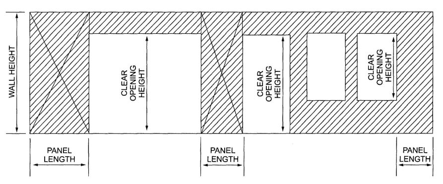
FIGURE R602.10.4.2
BRACED WALL PANELS WITH CONTINUOUS SHEATHING
| METHOD | ADJACENT CLEAR OPENING HEIGHT (inches) | WALL HEIGHT (feet) | ||||
|---|---|---|---|---|---|---|
| 8 | 9 | 10 | 11 | 12 | ||
| For SI: 1 inch = 25.4 mm, 1 foot = 304.8 mm. | ||||||
| a. Interpolation shall be permitted. | ||||||
| CS-WSP | 64 | 24 | 27 | 30 | 33 | 36 |
| 68 | 26 | 27 | 30 | — | — | |
| 72 | 28 | 27 | 30 | — | — | |
| 76 | 29 | 30 | 30 | — | — | |
| 80 | 31 | 33 | 30 | — | — | |
| 84 | 35 | 36 | 33 | — | — | |
| 88 | 39 | 39 | 36 | — | — | |
| 92 | 44 | 42 | 39 | — | — | |
| 96 | 48 | 45 | 42 | — | — | |
| 100 | — | 48 | 45 | — | — | |
| 104 | — | 51 | 48 | — | — | |
| 108 | — | 54 | 51 | — | — | |
| 112 | — | — | 54 | 44 | — | |
| 116 | — | — | 57 | — | — | |
| 120 | — | — | 60 | — | — | |
| 122 | — | — | — | — | 48 | |
| 132 | — | — | — | 66 | — | |
| 144 | — | — | — | — | 75 | |
| CS-G | ≤120 | 24 | 27 | 30 | — | — |
| CS-PF | ≤120 | 16 | 18 | 20 | — | — |
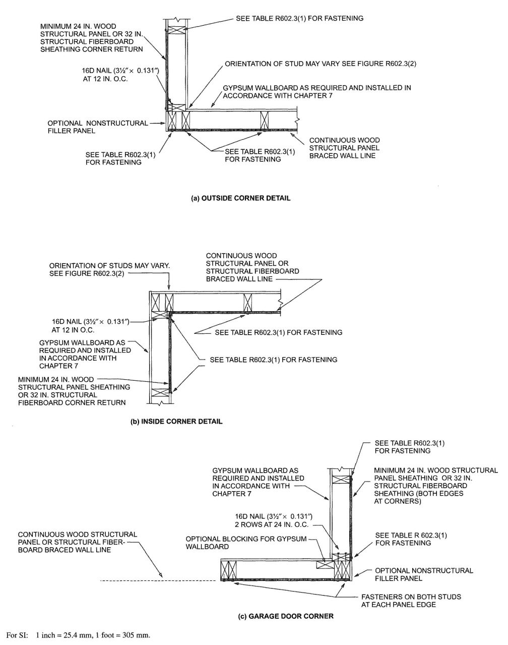
FIGURE R602.10.4.4(1)
TYPICAL EXTERIOR CORNER FRAMING FOR CONTINUOUS SHEATHING
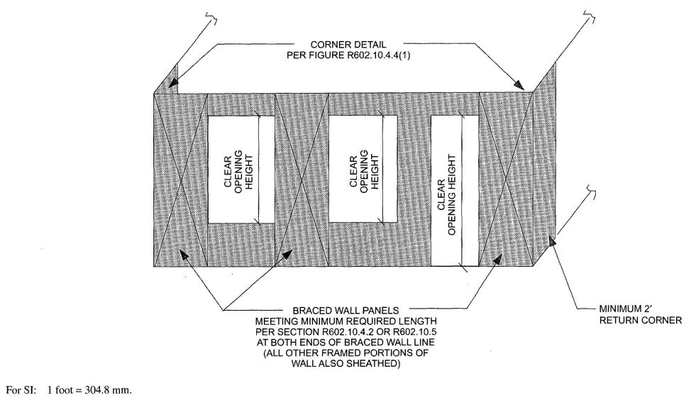
FIGURE R602.10.4.4(2)
BRACED WALL LINE WITH CONTINUOUS SHEATHING WITH CORNER RETURN PANEL
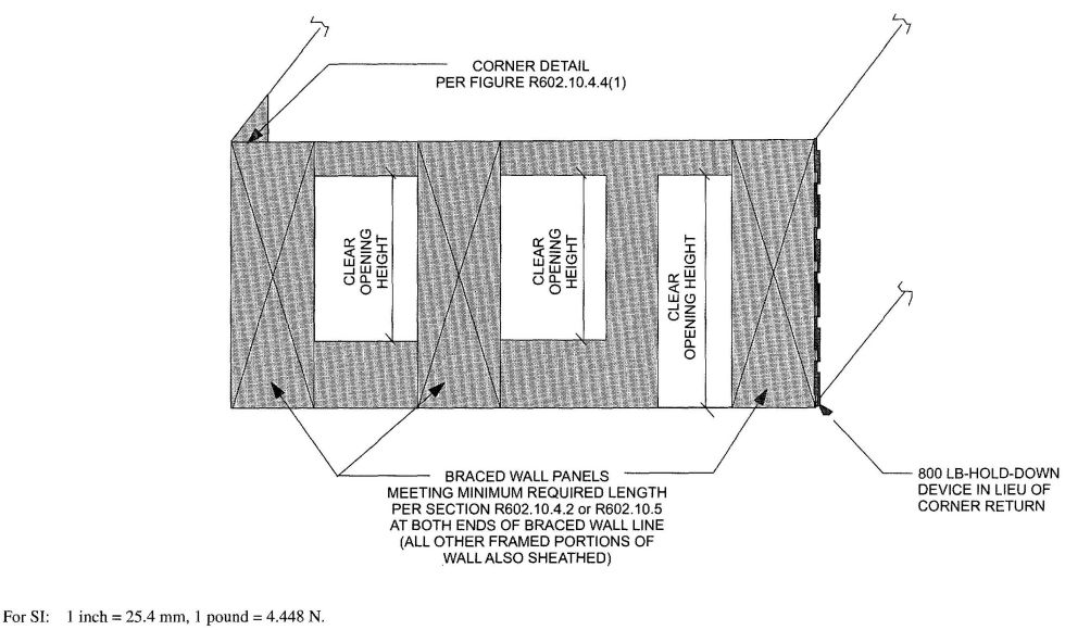
FIGURE R602.10.4.4(3)
BRACED WALL LINE WITH CONTINUOUS SHEATHING WITHOUT CORNER RETURN PANEL
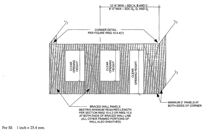
FIGURE R602.10.4.4(4)
BRACED WALL LINE WITH CONTINUOUS SHEATHING FIRST BRACED WALL PANEL
AWAY FROM END OF WALL LINE WITHOUT TIE DOWN
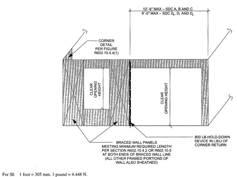
FIGURE R602.10.4.4(5)
BRACED WALL LINE WITH CONTINUOUS SHEATHING—FIRST BRACED WALL
PANEL AWAY FROM END OF WALL LINE WITH HOLD-DOWN
R602.10.5 Continuously-sheathed braced wall line using Method CS-SFB (structural fiberboard sheathing). Continuously sheathed braced wall lines using structural fiberboard sheathing shall comply with this section. Different bracing methods shall not be permitted within a continuously sheathed braced wall line. Other bracing methods prescribed by this code shall be permitted on other braced wall lines on the same story level or on different story levels of the building.
R602.10.5.1 Continuously sheathed braced wall line requirements. Continuously-sheathed braced wall lines shall be in accordance with Figure R602.10.4.2 and shall comply with all of the following requirements:
R602.10.5.2 Braced wall panel length. In a continuously-sheathed structural fiberboard braced wall line, the minimum braced wall panel length shall be in accordance with Table R602.10.5.2.
R602.10.5.3 Braced wall panel location and corner construction. A braced wall panel shall be located at each end of a continuously-sheathed braced wall line. A minimum 32-inch (813 mm) structural fiberboard sheathing panel corner return shall be provided at both ends of a continuously-sheathed braced wall line in accordance with Figure R602.10.4.4(1) In lieu of the corner return, a hold-down device with a minimum uplift design value of 800 pounds (3560 N) shall be fastened to the corner stud and to the foundation or framing below in accordance with Figure R602.10.4.4(3).
Exception: The first braced wall panel shall be permitted to begin 12 feet 6 inches (3810 mm) from each end of the braced wall line in Seismic Design Categories A, B and C provided one of the following is satisfied:
- A minimum 32-inch-long (813 mm), full-height structural fiberboard sheathing panel is provided at both sides of a corner constructed in accordance with Figure R602.10.4.4(1) at the braced wall line ends in accordance with Figure R602.10.4.4(4), or
- The braced wall panel closest to the corner shall have a hold-down device with a minimum uplift design value of 800 pounds (3560 N) fastened to the stud at the edge of the braced wall panel closest to the corner and to the foundation or framing below in accordance with Figure R602.10.4.4(5).
R602.10.5.4 Continuously sheathed braced wall lines. Where a continuously-sheathed braced wall line is used in Seismic Design Categories D0 D1 and D2 or regions where the basic wind speed exceeds 100 miles per hour (45 m/s), the braced wall line shall be designed in accordance with accepted engineering practice and the provisions of the California Building Code. Also, all other exterior braced wall lines in the same story shall be continuously sheathed.
R602.10.6 Braced wall panel connections. Braced wall panels shall be connected to floor framing or foundations as follows:
| MINIMUM LENGTH OF STRUCTURAL FIBERBOARD BRACED WALL PANEL (inches) | MINIMUM OPENING CLEAR HEIGHT NEXT TO THE STRUCTURAL FIBERBOARD BRACED WALL PANEL (% of wall height) | ||
|---|---|---|---|
| 8-foot wall | 9-foot wall | 10-foot wall | |
| For SI: 1 inch = 25.4 mm, 1 foot = 304.8 mm. | |||
| a. Interpolation is permitted. | |||
| 48 | 54 | 60 | 100 |
| 32 | 36 | 40 | 85 |
| 24 | 27 | 30 | 67 |
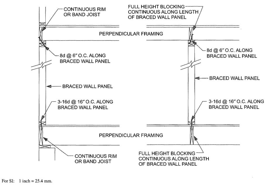
FIGURE R602.10.6(1)
BRACED WALL PANEL CONNECTION WHEN PERPENDICULAR TO FLOOR/CEILING FRAMING
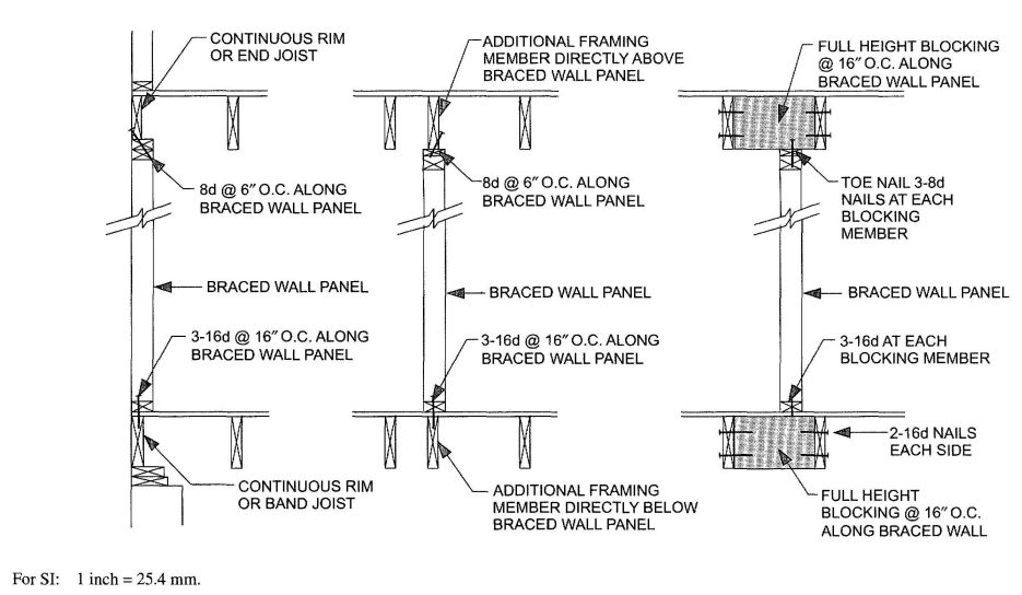
FIGURE R602.10.6(2)
BRACED WALL PANEL CONNECTION WHEN PARALLEL TO FLOOR/CEILING FRAMING
R602.10.6.1 Braced wall panel connections for Seismic Design Categories D0, D1 and D2. Braced wall panels shall be fastened to required foundations in accordance with Section R602.11.1, and top plate lap splices shall be face-nailed with at least eight 16d nails on each side of the splice.
R602.10.6.2 Connections to roof framing. Exterior braced wall panels shall be connected to roof framing as follows.
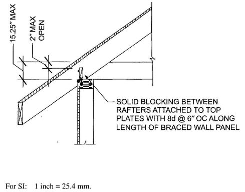
Lateral support for the rafters and ceiling joists shall be provided in accordance with Section R802.8. Lateral support for trusses shall be provided in accordance with Section R802.10.3. Ventilation shall be provided in accordance with Section R806.1.
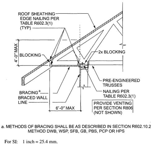
FIGURE R602.10.6.2(2)
BRACED WALL PANEL CONNECTION OPTION TO PERPENDICULAR RAFTERS OR ROOF TRUSSES
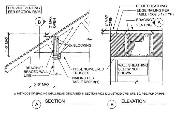
FIGURE R602.10.6.2(3)
BRACED WALL PANEL CONNECTION OPTION TO PERPENDICULAR RAFTERS OR ROOF TRUSSES
R602.10.7 Braced wall panel support. Braced wall panel support shall be provided as follows:
R602.10.7.1 Braced wall panel support for Seismic Design Category D2. In one-story buildings located in Seismic Design Category D2, braced wall panels shall be supported on continuous foundations at intervals not exceeding 50 feet (15 240 mm). In two-story buildings located in Seismic Design Category D2, all braced wall panels shall be supported on continuous foundations.
Exception: Two-story buildings shall be permitted to have interior braced wall panels supported on continuous foundations at intervals not exceeding 50 feet (15 240 mm) provided that:
- The height of cripple walls does not exceed 4 feet (1219 mm).
- First-floor braced wall panels are supported on doubled floor joists, continuous blocking or floor beams.
- The distance between bracing lines does not exceed twice the building width measured parallel to the braced wall line.
R602.10.8 Panel joints. All vertical joints of panel sheathing shall occur over, and be fastened to common studs. Horizontal joints in braced wall panels shall occur over, and be fastened to common blocking of a minimum 1½ inch (38 mm) thickness.
Exceptions:
- Blocking at horizontal joints shall not be required in wall segments that are not counted as braced wall panels.
- Where the bracing length provided is at least twice the minimum length required by Tables R602.10.1.2(1) and R602.10.1.2(2) blocking at horizontal joints shall not be required in braced wall panels constructed using Methods WSP, SFB, GB, PBS or HPS.
- When Method GB panels are installed horizontally, blocking of horizontal joints is not required.
R602.10.9 Cripple wall bracing. In Seismic Design Categories other than D2, cripple walls shall be braced with a length and type of bracing as required for the wall above in accordance with Tables R602.10.1.2(1) and R602.10.1.2(2) with the following modifications for cripple wall bracing:
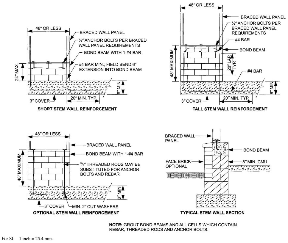
FIGURE R602.10.7
MASONRY STEM WALLS SUPPORTING BRACED WALL PANELS
R602.10.9.1 Cripple wall bracing in Seismic Design Categories D0,D1 and D2. In addition to the requirements of Section R602.10.9, where braced wall lines at interior walls occur without a continuous foundation below, the length of parallel exterior cripple wall bracing shall be 1½ times the length required by Tables R602.10.1.2(1) and R602.10.1.2(2). Where cripple walls braced using Method WSP of Section R602.10.2 cannot provide this additional length, the capacity of the sheathing shall be increased by reducing the spacing of fasteners along the perimeter of each piece of sheathing to 4 inches (102 mm) on center.
In Seismic Design Category D2, cripple walls shall be braced in accordance with Tables R602.10.1.2(1) and R602.10.1.2(2).
R602.10.9.2 Redesignation of cripple walls. In any Seismic Design Category, cripple walls shall be permitted to be redesignated as the first story walls for purposes of determining wall bracing requirements. If the cripple walls are redesignated, the stories above the redesignated story shall be counted as the second and third stories, respectively.
R602.11 Wall anchorage. Braced wall line sills shall be anchored to concrete or masonry foundations in accordance with Sections R403.1.6 and R602.11.1.
602.11.1 Wall anchorage for all buildings in Seismic Design Categories D0, D1 and D2 and townhouses in Seismic Design Category C. Plate washers, a minimum of 0.229 inch by 3 inches (5.8 mm by 76 mm by 76 mm) in size, shall be provided between the foundation sill plate and the nut except where approved anchor straps are used. The hole in the plate washer is permitted to be diagonally slotted with a width of up to 3/16 inch (5 mm) larger than the bolt diameter and a slot length not to exceed 1¾ inches (44 mm), provided a standard cut washer is placed between the plate washer and the nut.
238R602.11.2 Stepped foundations in Seismic Design Categories D0’ D1 and D2. In all buildings located in Seismic Design Categories D0’ D1 or D2’ where the height of a required braced wall line that extends from foundation to floor above varies more than 4 feet (1219 mm), the braced wall line shall be constructed in accordance with the following:
R602.12 Wall bracing and stone and masonry veneer. Where stone and masonry veneer is installed in accordance with Section R703.7, wall bracing shall comply with this section.
For all buildings in Seismic Design Categories A, B and C, wall bracing at exterior and interior braced wall lines shall be in accordance with Section R602.10 and the additional requirements of Table R602.12(1).
For detached one- or two-family dwellings in Seismic Design Categories D0’ D1 and D2’ wall bracing and hold downs at exterior and interior braced wall lines shall be in accordance with Sections R602.10 and R602.11 and the additional requirements of Section R602.12.1 and Table R602.12(2). In Seismic Design Categories D0’ D1 and D2 cripple walls are not permitted, and required interior braced wall lines shall be supported on continuous foundations.
R602.12.1 Seismic Design Categories D0’ D1 and D2’ Wall bracing where stone and masonry veneer exceeds the first story height in Seismic Design Categories D0’ D 1 and D2 shall conform to the requirements of Sections R602.10 and R602.11 and the following requirements.
R602.12.1.1 Length of bracing. The length of bracing along each braced wall line shall be in accordance with Table R602.12(2).
R602.12.1.2 Braced wall panel location. Braced wall panels shall begin no more than 8 feet (2440 mm) from each end of a braced wall line and shall be spaced a maximum of 25 feet (7620 mm) on center.
R602.12.1.3 Braced wall panel construction. Braced wall panels shall be constructed of sheathing with a thickness of not less than 7/16 inch (11 mm) nailed with 8d common nails spaced 4 inches (102 mm) on center at all panel edges and 12 inches (305 mm) on center at intermediate supports. The end of each braced wall panel shall have a hold down device in accordance with Table R602.12(2) installed at each end. Size, height and spacing of wood studs shall be in accordance with Table R602.3(5).
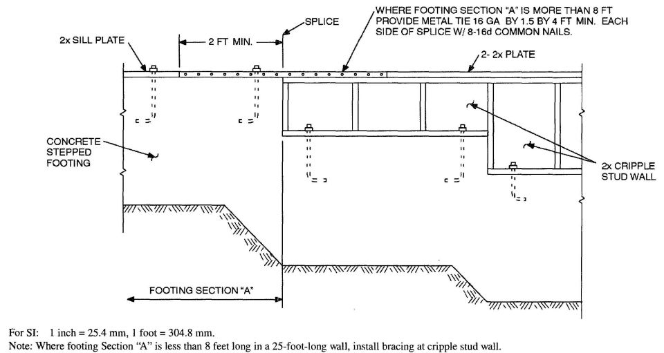
FIGURE R602.11.2
STEPPED FOUNDATION CONSTRUCTION
| SEISMIC DESIGN CATEGORY | NUMBER OF WOOD FRAMED STORIES | WOOD FRAMED STORY | MINIMUM SHEATHING AMOUNT (length of braced wall line length)a |
|---|---|---|---|
| a. Applies to exterior and interior braced wall lines. | |||
| A or B | 1,2 or 3 | all | Table R602.10.1.2(2) |
| C | 1 | 1 only | Table R602.10.1.2(2) |
| 2 | top | Table R602.10.1.2(2) | |
| bottom | 1.5 times length required by Table R602.10.1.2(2) | ||
| 3 | top | Table R602.10.1.2(2) | |
| middle | 1.5 times length required by Table R602.10.1.2(2) | ||
| bottom | 1.5 times length required by Table R602.10.1.2(2) | ||
| SEISMIC DESIGN CATEGORY | NUMBER OF STORIESa | STORY | MINIMUM SHEATHING AMOUNT (percent of braced wall line length)b | MINIMUM SHEATHING THICKNESS AND FASTENING | SINGLE STORY HOLD DOWN FORCE (lb)c | CUMULATIVE HOLD DOWN FORCE (lb)d |
|---|---|---|---|---|---|---|
| For SI: 1 inch = 25.4 mm, 1 foot = 304.8 mm, 1 pound per square foot = 0.479kPa, 1 pound-force = 4.448 N. | ||||||
| a. Cripple walls are not permitted in Seismic Design Categories D0’ D1 and D2’ | ||||||
| b. Applies to exterior and interior braced wall lines. | ||||||
| c. Hold down force is minimum allowable stress design load for connector providing uplift tie from wall framing at end of braced wall panel at the noted story to wall framing at end of braced wall panel at the story below, or to foundation or foundation wall. Use single story hold down force where edges of braced wall panels do not align; a continuous load path to the foundation shall be maintained. [See Figure R602.12]. | ||||||
| d. Where hold down connectors from stories above align with stories below, use cumulative hold down force to size middle and bottom story hold down connectors.(See Figure R602.12). | ||||||
| D0 | 1 | 1 only | 35 | 7/16-inch wood structural panel sheathing with 8d common nails spaced at 4 inches on center at panel edges, 12 inches on center at intermediate supports; 8d common nails at 4 inches on center at braced wall panel end posts with hold down attached | N/A | — |
| 2 | top | 35 | 1900 | — | ||
| bottom | 45 | 3200 | 5100 | |||
| 3 | top | 40 | 1900 | — | ||
| middle | 45 | 3500 | 5400 | |||
| bottom | 60 | 3500 | 8900 | |||
| D1 | 1 | 1 only | 45 | 2100 | — | |
| 2 | top | 45 | 2100 | — | ||
| bottom | 45 | 3700 | 5800 | |||
| 3 | top | 45 | 2100 | — | ||
| middle | 45 | 3700 | 5800 | |||
| bottom | 60 | 3700 | 9500 | |||
| D2 | 1 | 1 only | 55 | 2300 | — | |
| 2 | top | 55 | 2300 | — | ||
| bottom | 55 | 3900 | 6200 | |||
R602.12.1.4 Minimum length of braced panel. Each braced wall panel shall be at least 48 inches (1219 mm) in length, covering a minimum of 3 stud spaces where studs are spaced 16 inches (406 mm) on center and covering a minimum of 2 stud spaced where studs are spaced 24 inches on center.
R602.12.1.5 Alternate braced wall panel. Alternate braced wall panels described in Section R602.10.3.2 shall not replace the braced wall panel specification of this section.
R602.12.1.6 Continuously sheathed wall bracing. Continuously sheathed provisions of Section R602.10.4 shall not be used in conjunction with the wall bracing provisions of this section.
R603.1 General. Elements shall be straight and free of any defects that would significantly affect structural performance.
R603.1.1 Applicability limits. The provisions of this section shall control the construction of exterior cold-formed steel wall framing and interior load-bearing cold-formed steel wall framing for buildings not more than 60 feet (18 288 mm) long perpendicular to the joist or truss span, not more than 40 feet (12 192 mm) wide parallel to the joist or truss span, and less than or equal to three stories above grade plane. All exterior walls installed in accordance with the provisions of this section shall be considered as load-bearing walls. Cold-formed steel walls constructed in accordance with the provisions of this section shall be limited to sites subjected to a maximum design wind speed of 110 miles per hour (49 m⁄s) Exposure B or C and a maximum ground snow load of 70 pounds per square foot (3.35 kPa).
R603.1.2 In-line framing. Load-bearing cold-formed steel studs constructed in accordance with Section R603 shall be located in-line with joists, trusses and rafters in accordance with Figure R603.1.2 and the tolerances specified as follows:
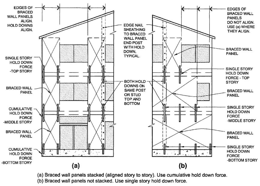
FIGURE R602.12
HOLD DOWNS AT EXTERIOR AND INTERIOR BRACED WALL PANELS
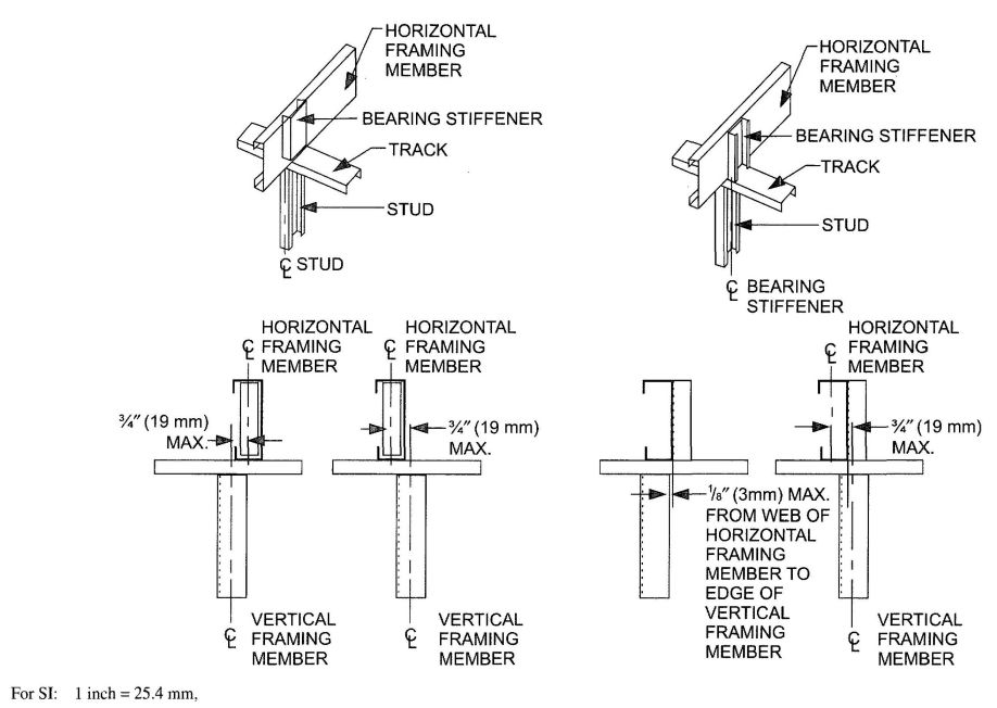
FIGURE R603.1.2
IN-LINE FRAMING
R603.2 Structural framing. Load-bearing cold-formed steel wall framing members shall comply with Figure R603.2(1) and with the dimensional and minimum thickness requirements specified in Table R603.2(1) and R603.2(2). Tracks shall comply with Figure R603.2(2) and shall have a minimum flange width of 1¼ inches (32 mm). The maximum inside bend radius for members shall be the greater of 32⁄ inch (2.4 mm) minus half the base steel thickness or 1.5 times the base steel thickness.
R603.2.1 Material. Load-bearing cold-formed steel framing members shall be cold-formed to shape from structural quality sheet steel complying with the requirements of one of the following:
R603.2.2 Identification. Load-bearing cold-formed steel framing members shall have a legible label, stencil, stamp or embossment with the following information as a minimum:
R603.2.3 Corrosion protection. Load-bearing cold-formed steel framing shall have a metallic coating complying with ASTM A 1003 and one of the following:
R603.2.4 Fastening requirements. Screws for steel-to-steel connections shall be installed with a minimum edge distance and center-to-center spacing of 1½ inch (12.7 mm), shall be self-drilling tapping and shall conform to ASTM C 1513. Structural sheathing shall be attached to cold-formed steel studs with minimum No.8 self-drilling tapping screws that conform to ASTM C 1513. Screws for attaching structural sheathing to cold-formed steel wall framing shall have a minimum head diameter of 0.292 inch (7.4 mm) with counter sunk heads and shall be installed with a minimum edge distance of 3⁄8 inch (9.5 mm). Gypsum board shall be attached to cold-formed steel wall framing with minimum No. 6 screws conforming to ASTM C 954 or ASTM C 1513 with a bugle head style and shall be installed in accordance with Section R702. For all connections, screws shall extend through the steel a minimum of three exposed threads. All fasteners shall have rust inhibitive coating suitable for the
| MEMBER DESIGNATIONa | WEB DEPTH (inches) | MINIMUM FLANGE WIDTH (inches) | MAXIMUM FLANGE WIDTH (inches) | MINIMUM LIP SIZE (inches) |
|---|---|---|---|---|
| For SI: 1 inch = 25.4 mm; 1 mil = 0.0254 mm. | ||||
| a. The member designation is defined by the first number representing the member depth in hundredths of an inch “S“ representing a stud or joist member, the second number representing the flange width in hundredths of an inch, and the letter “t” shall be a number representing the minimum base metal thickness in mils. [See Table R603.2(2)]. | ||||
| 350S162-t | 3.5 | 1.625 | 2 | 0.5 |
| 550S162-t | 5.5 | 1.625 | 2 | 0.5 |
| DESIGNATION THICKNESS (mils) | MINIMUM BASE STEEL THICKNESS (inches) |
|---|---|
| For SI: 1 mil = 0.0254 mm, 1 inch = 25.4 mm. | |
| 33 | 0.0329 |
| 43 | 0.0428 |
| 54 | 0.0538 |
| 68 | 0.0677 |
| 97 | 0.0966 |
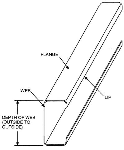
FIGURE R603.2(1)
C-SHAPED SECTION
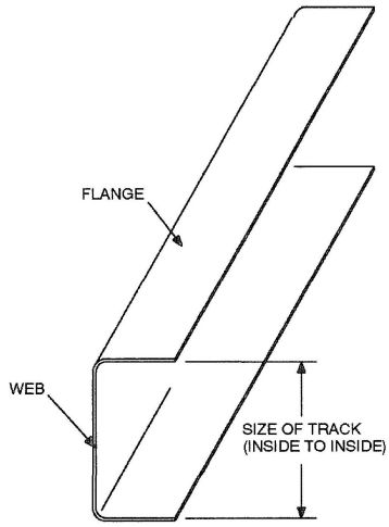
FIGURE R603.2(2)
TRACK SECTION
installation in which they are being used, or be manufactured from material not susceptible to corrosion.
Where No. 8 screws are specified in a steel-to-steel connection, the required number of screws in the connection is permitted to be reduced in accordance with the reduction factors in Table R603.2.4, when larger screws are used or when one of the sheets of steel being connected is thicker than 33 mils (0.84 mm). When applying the reduction factor, the resulting number of screws shall be rounded up.
| SCREW SIZE | THINNEST CONNECTED STEEL SHEET (mills) | |
|---|---|---|
| 33 | 43 | |
| For SI: 1 mil = 0.0254 mm. | ||
| 8 | 1.0 | 0.67 |
| 10 | 0.93 | 0.62 |
| 12 | 0.86 | 0.56 |
R603.2.5 Web holes, web hole reinforcing and web hole patching. Web holes, web hole reinforcing and web hole patching shall be in accordance with this section.
R603.2.5.1 Web holes. Web holes in wall studs and other structural members shall comply with all of the following conditions:
Framing members with web holes not conforming to the above requirements shall be reinforced in accordance with Section R603.2.5.2, patched in accordance with Section R603.2.5.3 or designed in accordance with accepted engineering practice.
R603.2.5.2 Web hole reinforcing. Web holes in gable end wall studs not conforming to the requirements of Section R603.2.5.1 shall be permitted to be reinforced if the hole is located fully within the center 40 percent of the span and the depth and length of the hole does not exceed 65 percent of the flat width of the web. The reinforcing shall be a steel plate or C-shape section with a
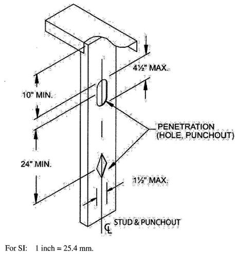
FIGURE R603.2.5.1
WEB HOLES
hole that does not exceed the web hole size limitations of Section R603.2.5.1 for the member being reinforced. The steel reinforcing shall be the same thickness as the receiving member and shall extend at least 1 inch (25.4 mm) beyond all edges of the hole. The steel reinforcing shall be fastened to the web of the receiving member with No.8 screws spaced no more than 1 inch (25.4 mm) center-to-center along the edges of the patch with minimum edge distance of ½ inch (12.7 mm).
R603.2.5.3 Hole patching. Web holes in wall studs and other structural members not conforming to the requirements in Section R603.2.5.1 shall be permitted to be patched in accordance with either of the following methods:
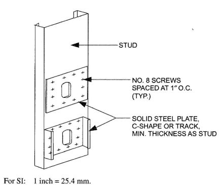
FIGURE R603.2.5.3
STUD WEB HOLE PATCH
R603.3 Wall construction. All exterior cold-formed steel framed walls and interior load-bearing cold-formed steel framed walls shall be constructed in accordance with the provisions of this section.
R603.3.1 Wall to foundation or floor connection. Cold- formed steel framed walls shall be anchored to foundations or floors in accordance with Table R603.3.1 and Figure R603.3.1(1), R603.3.1(2) or R603.3.1(3). Anchor bolts shall be located not more than 12 inches (305 mm) from corners or the termination of bottom tracks. Anchor bolts shall extend a minimum of 15 inches (381 mm) into masonry or 7 inches (178 mm) into concrete. Foundation anchor straps shall be permitted, in lieu of anchor bolts, if spaced as required to provide equivalent anchorage to the required anchor bolts and installed in accordance with manufacturer's requirements.
R603.3.1.1 Gable endwalls. Gable endwalls with heights greater than 10 feet (3048 mm) shall be anchored to foundations or floors in accordance with Tables R603.3.1.1(1) or R603.3.1.1(2).
R603.3.2 Minimum stud sizes. Cold-formed steel walls shall be constructed in accordance with Figures R603.3.1(1), R603.3.1(2), or R603.3.1(3), as applicable. Exterior wall stud size and thickness shall be determined in accordance with the limits set forth in Tables R603.3.2(2) through R603.3.2(31). Interior load-bearing wall stud size and thickness shall be determined in accordance with the limits set forth in Tables R603.3.2(2) through R603.3.2(31) based upon an 85 miles per hour (38 m⁄s) Exposure A⁄B wind value and the building width, stud spacing and snow load, as appropriate. Fastening requirements shall be in accordance with Section R603.2.4 and Table R603.3.2(1). Top and bottom tracks shall have the same minimum thickness as the wall studs.
Exterior wall studs shall be permitted to be reduced to the next thinner size, as shown in Tables R603.3.2(2) through R603.3.2(31), but not less than 33 mils (0.84 mm), where both of the following conditions exist:
Interior load-bearing walls shall be permitted to be reduced to the next thinner size, as shown in Tables R603.3.2(2) through R603.3.2(31), but not less than 33 miles (0.84 mm), where a minimum of ½ inch (12.7 mm) gypsum board is installed and fastened in accordance with Section R702 on both sides of the wall. The tabulated stud thickness for load-bearing walls shall be used when the attic storage load is 10 pounds per square feet (480 Pa) or less. A limited attic storage load of 20 pounds per square feet (960 Pa) shall be permitted provided that the next higher snow load column is used to select the stud size from Tables R603.3.2(2) through R603.3.2(31).
For two-story buildings, the tabulated stud thickness for walls supporting one floor, roof and ceiling shall be used when second floor live load is 30 pounds per square feet (1440 Pa). Second floor live loads of 40 psf (1920 pounds per square feet) shall be permitted provided that the next higher snow load column is used to select the stud size from Tables R603.3.2(2) through R603.3.2(21).
For three-story buildings, the tabulated stud thickness for walls supporting one or two floors, roof and ceiling shall be used when the third floor live load is 30 pounds per square feet (1440 Pa). Third floor live loads of 40 pounds per square feet (1920 Pa) shall be permitted provided that the next higher snow load column is used to select the stud size from Tables R603.3.2(22) through R603.3.2(31).
R603.3.2.1 Gable endwalls. The size and thickness of gable endwall studs with heights less than or equal to 10 feet (3048 mm) shall be permitted in accordance with the limits set forth in Tables R603.3.2.1 (1) or R603.3.2.1(2). The size and thickness of gable endwall studs with heights greater than 10 feet (3048 mm) shall be determined in accordance with the limits set forth in Tables R603.3.2.1(3) or R603.3.2.1(4).
R603.3.3 Stud bracing. The flanges of cold-formed steel studs shall be laterally braced in accordance with one of the following:
R603.3.4 Cutting and notching. Flanges and lips of cold-formed steel studs and headers shall not be cut or notched.
R603.3.5 Splicing. Steel studs and other structural members shall not be spliced. Tracks shall be spliced in accordance with Figure R603.3.5.
R603.4 Corner framing. In exterior walls, corner studs and the top tracks shall be installed in accordance with Figure R603.4.
R603.5 Exterior wall covering. The method of attachment of exterior wall covering materials to cold-formed steel stud wall framing shall conform to the manufacturer's installation instructions.
| FRAMING CONDITION | WIND SPEED (mph) AND EXPOSURE | |||||
|---|---|---|---|---|---|---|
| 85B | 90B | 100B 85C | 110B 90C | 100C | <110C | |
| For SI: 1 inch = 25.4 mm, 1 mile per hour = 0.447 m/s, 1 foot = 304.8 mm, 1 1b = 4.45 N. | ||||||
| a.Anchor bolts are to be located not more than 12 inches from corners or the termination of bottom tracks (e.g., at door openings or corners). Bolts are to extend a minimum of 15 inches into masonry or 7 inches into concrete. | ||||||
| b. All screw sizes shown are minimum. | ||||||
| c. NR= uplift connector not required. | ||||||
| d. Foundation anchor straps are permitted in place of anchor bolts, if spaced as required to provide equivalent anchorage to the required anchor bolts and installed in accordance with manufacturer’s requirements. | ||||||
| Wall bottom track to floor per Figure R603.3.1(1) | 1-No. 8 screw at 12″ o.c. | 1-No. 8 screw at 12″ o.c. | 1-No. 8 screw at 12″ o.c. | 2-No. 8 screw at 12″ o.c. | 2-No. 8 screws at 12″ o.c. | 2 No. 8 screws at 12″ o.c. |
| Wall bottom track to foundation per Figure R603.3.1(2)d | ½″ minimum diameter anchor bolt at 6′; o.c. | ½″ minimum diameter anchor bolt at 6′; o.c. | ½″ minimum diameter anchor bolt at 4′; o.c. | ½″ minimum diameter anchor bolt at 4′; o.c. | ½″ minimum diameter anchor bolt at 4′; o.c. | ½″ minimum diameter anchor bolt at 4′; o.c. |
| Wall bottom track to wood sill per Figure R603.3.1(3) | Steel plate spaced at 4′; o.c., with 4-No. 8 screws and 4-10d or 6-8d common nails | Steel plate spaced at 4′; o.c., with 4-No. 8 screws and 4-10d or 6-8d common nails | Steel plate spaced at 3′; o.c., with 4-No. 8 screws and 4-10d or 6-8d common nails | Steel plate spaced at 3′; o.c., with 4-No. 8 screws and 4-10d or 6-8d common nails | Steel plate spaced at 2′; o.c., with 4-No. 8 screws and 4-10d or 6-8d common nails | Steel plate spaced at 2′; o.c., with 4-No. 8 screws and 4-10d or 6-8d common nails |
| Wind uplift connector strength to 16″ stud spacingc | NR | NR | NR | NR | NR | 65 1b per foot of wall length |
| Wind uplift connector strength for 24″ stud spacingc | NR | NR | NR | NR | NR | 100 1b per foot of wall length |
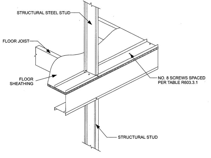
FIGURE R603.3.1(1)
WALL TO FLOOR CONNECTION
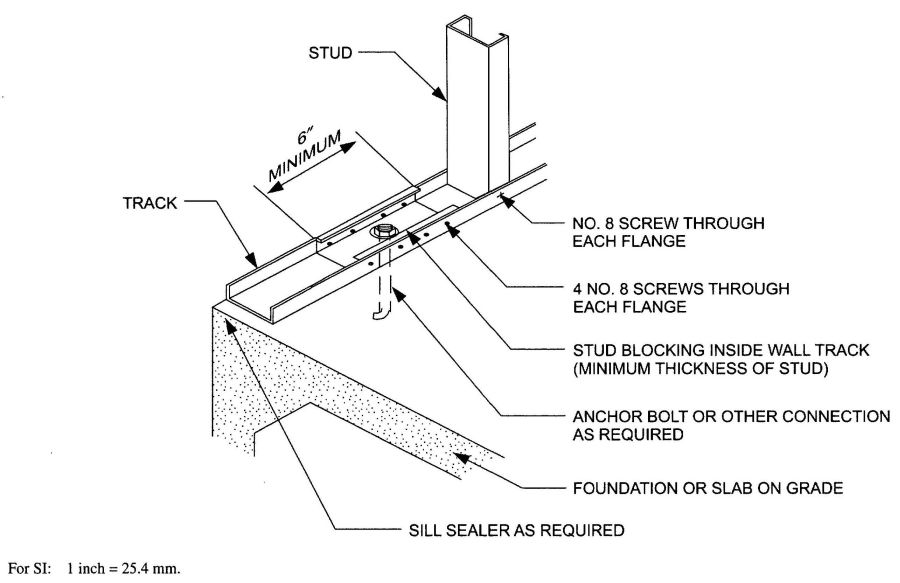
FIGURE R603.3.1(2)
WALL TO FOUNDATION CONNECTION
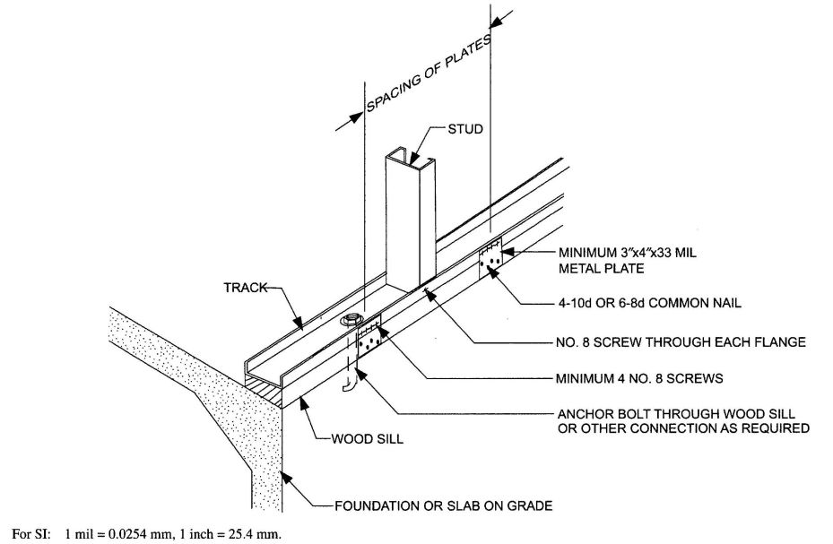
FIGURE R603.3.1(3)
WALL TO WOOD SILL CONNECTION
| BASIC WIND SPEED (mph) | WALL BOTTOM TRACK TO FLOOR JOIST OR TRACK CONNECTION | |||
|---|---|---|---|---|
| Exposure | Stud height, h (ft) | |||
| B | C | 10<h≤14 | 14<h≤18 | 18<h≤22 |
| For SI: 1 inch = 25.4 mm, 1 mile per hour = 0.447 m/s, 1 foot = 304.8 mm. | ||||
| a. Refer to Table R603.3.1.1 (2) for gable endwall bottom track to foundation connections. | ||||
| b. Where attachment is not given, special design is required. | ||||
| c. Stud height, h, is measured from wall bottom track to wall top track or brace connection height. | ||||
| 85 | — | 1-No. 8 screw @ 12″ o.c. | 1-No. 8 screw @ 12″ o.c. | 1-No. 8 screw @ 12″ o.c. |
| 90 | — | 1-No. 8 screw @ 12″ o.c. | 1-No. 8 screw @ 12″ o.c. | 1-No. 8 screw @ 12″ o.c. |
| 100 | 85 | 1-No. 8 screw @ 12″ o.c. | 1-No. 8 screw @ 12″ o.c. | 1-No. 8 screw @ 12″ o.c. |
| 110 | 90 | 1-No. 8 screw @ 12″ o.c. | 1-No. 8 screw @ 12″ o.c. | 2-No. 8 screws @ 12″ o.c. |
| — | 100 | 1-No. 8 screw @ 12″ o.c. | 2-No. 8 screws @ 12″ o.c. | 1-No. 8 screw @ 8″ o.c. |
| — | 110 | 2-No. 8 screws @ 12″ o.c. | 1-No. 8 screw @ 8″ o.c. | 2-No. 8 screws @ 8″ o.c. |
| BASIC WIND SPEED (mph) | WALL BOTTOM TRACK TO FLOOR JOIST OR TRACK CONNECTION | |||
|---|---|---|---|---|
| Exposure | Stud height, h (ft) | |||
| B | C | 10<h≤14 | 14<h≤18 | 18<h≤22 |
| For SI: 1 inch = 25.4 mm, 1 mile per hour = 0.447 m/s, 1 foot = 304.8 mm. | ||||
| a. Refer to Table R603.3.1.1(1) for gable endwall bottom track to floor joist or track connections. | ||||
| b. Where attachment is not given, special design is required. | ||||
| c. Stud height, h, is measured from wall bottom track to wall top track or brace connection height. | ||||
| d. Foundation anchor straps are permitted in place of anchor bolts if spaced as required to provide equivalent anchorage to the required anchor bolts and installed in accordance with manufacturer’s requirements. | ||||
| 85 | — | 6′;-0″ o.c. | 6′;-0″ o.c. | 6′;-0″ o.c. |
| 90 | — | 6′;-0″ o.c. | 5′;-7″ o.c. | 6′;-0″ o.c. |
| 100 | 85 | 5′;-10″ o.c. | 6′;-0″ o.c. | 6′;-0″ o.c. |
| 110 | 90 | 4′;-10″ o.c. | 5′;-6″ o.c. | 6′;-0″ o.c. |
| — | 100 | 4′;-1″ o.c. | 6′;-0″ o.c. | 6′;-0″ o.c. |
| — | 110 | 5′;-1″ o.c. | 6′;-0″ o.c. | 5′;-2″ o.c. |
R603.6 Headers. Headers shall be installed above all wall openings in exterior walls and interior load-bearing walls. Box beam headers and back-to-back headers each shall be formed from two equal sized C-shaped members in accordance with Figures R603.6(1) and R603.6(2), respectively, and Tables R603.6(1) through R603.6(24). L-shaped headers shall be permitted to be constructed in accordance with AISI S230. Alternatively, headers shall be permitted to be designed and constructed in accordance with AISI S100, Section D4.
R603.6.1 Headers in gable endwalls. Box beam and back-to-back headers in gable endwalls shall be permitted to be constructed in accordance with Section R603.6 or with the header directly above the opening in accordance with Figures R603.6.1(1) and R603.6.1(2) and the following provisions:
R603.7 Jack and king studs. The number of jack and king studs installed on each side of a header shall comply with Table R603.7(1). King, jack and cripple studs shall be of the same dimension and thickness as the adjacent wall studs. Headers shall be connected to king studs in accordance with Table R603.7(2) and the following provisions:
R603.8 Head and sill track. Head track spans above door and window openings and sill track spans beneath window openings shall comply with Table R603.8. For openings less than 4 feet (1219 mm) in height that have both a head track and a sill track, multiplying the spans by 1.75 shall be permitted in Table R603.8. For openings less than or equal to 6 feet (1829 mm) in height that have both a head track and a sill track, multiplying the spans in Table R603.8 by 1.50 shall be permitted.
R603.9 Structural sheathing. Structural sheathing shall be installed in accordance with Figure R603.9 and this section on all sheathable exterior wall surfaces, including areas above and below openings.
R603.9.1 Sheathing materials. Structural sheathing panels shall consist of minimum 7/16-inch (11 mm) thick oriented strand board or 15/32-inch (12 mm) thick plywood.
R603.9.2 Determination of minimum length of full height sheathing. The minimum length of full height sheathing on each braced wall line shall be determined by multiplying the length of the braced wall line by the percentage obtained from Table R603.9.2(1) and by the plan aspect-ration adjustment factors obtained from Table R603.9.2(2). The minimum length of full height sheathing shall not be less than 20 percent of the braced wall line length.
To be considered full height sheathing, structural sheathing shall extend from the bottom to the top of the wall without interruption by openings. Only sheathed, full height wall sections, uninterrupted by openings, which are a minimum of 48 inches (1219 mm) wide, shall be counted toward meeting the minimum percentages in Table R603.9.2(1). In addition, structural sheathing shall comply with all of the following requirements:
R603.9.2.1 The minimum percentage of full-height structural sheathing shall be multiplied by 1.10 for 9 foot (2743 mm) high walls and multiplied by 1.20 for 10 foot (3048 mm) high walls.
R603.9.2.2 For hip roofed homes, the minimum percentages of full height sheathing in Table R603.9.2(1), based upon wind, shall be permitted to be multiplied by a factor of 0.95 for roof slopes not exceeding 7:12 and a factor of 0.9 for roof slopes greater than 7:12.
R603.9.2.3 In the lowest story of a dwelling, multiplying the percentage of full height sheathing required in Table R603.9.2(1) by 0.6, shall be permitted provided hold down anchors are provided in accordance with Section R603.9.4.2.
R603.9.3 Structural sheathing fastening. All edges and interior areas of structural sheathing panels shall be fastened to framing members and tracks in accordance with Figure R603.9 and Table R603.3.2(1). Screws for attachment of structural sheathing panels shall be bugle-head, flat-head, or similar head style with a minimum head diameter of 0.29 inch (8 mm).
For continuously-sheathed braced wall lines using wood structural panels installed with No. 8 screws spaced 4-inches (102 mm) on center at all panel edges and 12 inches (304.8 mm) on center on intermediate framing members, the following shall apply:
R603.9.4 Uplift connection requirements. Uplift connections shall be provided in accordance with this section.
R603.9.4.1 Where wind speeds are in excess of 100 miles per hour (45 m/s), Exposure C, walls shall be provided wind direct uplift connections in accordance with AISI S230, Section E13.3, and AISI S230, Section F7.2, as required for 110 miles per hour (49 m/s), Exposure C.
R603.9.4.2 Where the percentage of full height sheathing is adjusted in accordance with Section R603.9.2.3, a hold-down anchor, with a strength of 4,300 pounds (19 kN), shall be provided at each end of each full-height sheathed wall section used to meet the minimum percent sheathing requirements of Section R603.9.2. Hold down anchors shall be attached to back-to-back studs; structural sheathing panels shall have edge fastening to the studs, in accordance with Section R603.9.3 and AISI S230, Table E11-1.
A single hold down anchor, installed in accordance with Figure R603.9.2, shall be permitted at the corners of buildings.
R603.9.5 Structural sheathing for stone and masonry veneer. In Seismic Design Category C, where stone and masonry veneer is installed in accordance with Section R703.7, the length of structural sheathing for walls supporting one story, roof and ceiling shall be the greater of the amount required by Section R603.9.2 or 36 percent, modified by Section R603.9.2 except Section R603.9.2.2 shall not be permitted.
| DESCRIPTION OF BUILDING ELEMENT | NUMBER AND SIZE OF FASTENERSa | SPACING OF FASTENERS |
|---|---|---|
| For SI: 1 inch = 25.4 mm. | ||
| a. All screw sizes shown are minimum. | ||
| b. Screws for attachment of structural sheathing panels are to be bugle-head, flat-head, or similar head styles with a minimum head diameter of 0.29 inch. | ||
| Floor joist to track of load-bearing wall | 2-No. 8 screws | Each joist |
| Wall stud to top or bottom track | 2-No. 8 screws | Each end of stud, one per flange |
| Structural sheathing to wall studs | No. 8 screwsh | 6″ o.c. on edges and 12″ o.c. at intermediate supports |
| Roof framing to wall | Approved design or tie down in accordance with Section R802.11 | |
 |
|||||||||||||||
|---|---|---|---|---|---|---|---|---|---|---|---|---|---|---|---|
| WIND SPEED | MEMBER SIZE | STUD SPACING (inches) | MINIMUM STUD THICKNESS (mils) | ||||||||||||
| 8-Foot Studs | 9-Foot Studs | 10-Foot Studs | |||||||||||||
| Exp. B | Exp. C | Ground Snow Load (psf) | |||||||||||||
| 20 | 30 | 50 | 70 | 20 | 30 | 50 | 70 | 20 | 30 | 50 | 70 | ||||
| For SI: 1 inch = 25.4 mm, 1 foot = 304.8 mm, 1 mil = 0.0254 mm, 1 mile per hour = 0.447 m/s, 1 pound per square foot = 0.0479 kPa, 1 ksi = 1000 psi = 6.895 MPa. | |||||||||||||||
| a. Deflection criterion:L/240. | |||||||||||||||
| b. Design load assumptions: | |||||||||||||||
| Second floor dead load is 10 psf. | |||||||||||||||
| Second floor live load is 30 psf. | |||||||||||||||
| Roof/ceiling dead load is 12 psf. | |||||||||||||||
| Attic live load is 10 psf. | |||||||||||||||
| c. Building width is in the direction of horizontal framing members supported by the wall studs. | |||||||||||||||
| 85 mph | — | 350S162 | 16 | 33 | 33 | 33 | 33 | 33 | 33 | 33 | 33 | 33 | 33 | 33 | 33 |
| 24 | 33 | 33 | 33 | 43 | 33 | 33 | 33 | 43 | 33 | 33 | 43 | 43 | |||
| 550S162 | 16 | 33 | 33 | 33 | 33 | 33 | 33 | 33 | 33 | 33 | 33 | 33 | 33 | ||
| 24 | 33 | 33 | 33 | 33 | 33 | 33 | 33 | 33 | 33 | 33 | 33 | 33 | |||
| 90 mph | — | 350S162 | 16 | 33 | 33 | 33 | 33 | 33 | 33 | 33 | 33 | 33 | 33 | 33 | 33 |
| 24 | 33 | 33 | 33 | 43 | 33 | 33 | 33 | 43 | 33 | 33 | 43 | 43 | |||
| 550S162 | 16 | 33 | 33 | 33 | 33 | 33 | 33 | 33 | 33 | 33 | 33 | 33 | 33 | ||
| 24 | 33 | 33 | 33 | 33 | 33 | 33 | 33 | 33 | 33 | 33 | 33 | 33 | |||
| 100 mph | 85 mph | 350S162 | 16 | 33 | 33 | 33 | 33 | 33 | 33 | 33 | 33 | 33 | 33 | 33 | 33 |
| 24 | 33 | 33 | 33 | 43 | 33 | 33 | 33 | 43 | 43 | 43 | 43 | 43 | |||
| 550S162 | 16 | 33 | 33 | 33 | 33 | 33 | 33 | 33 | 33 | 33 | 33 | 33 | 33 | ||
| 24 | 33 | 33 | 33 | 43 | 33 | 33 | 33 | 33 | 33 | 33 | 33 | 43 | |||
| 110 mph | 90 mph | 350S162 | 16 | 33 | 33 | 33 | 33 | 33 | 33 | 33 | 33 | 33 | 33 | 33 | 33 |
| 24 | 33 | 33 | 33 | 43 | 43 | 43 | 43 | 43 | 43 | 43 | 43 | 54 | |||
| 550S162 | 16 | 33 | 33 | 33 | 33 | 33 | 33 | 33 | 33 | 33 | 33 | 33 | 33 | ||
| 24 | 33 | 33 | 33 | 43 | 33 | 33 | 33 | 33 | 43 | 43 | 43 | 43 | |||
| — | 100 mph | 350S162 | 16 | 33 | 33 | 33 | 33 | 33 | 33 | 33 | 33 | 43 | 43 | 43 | 43 |
| 24 | 43 | 43 | 43 | 43 | 43 | 43 | 43 | 43 | 54 | 54 | 54 | 54 | |||
| 550S162 | 16 | 33 | 33 | 33 | 33 | 33 | 33 | 33 | 33 | 33 | 33 | 33 | 33 | ||
| 24 | 33 | 33 | 33 | 43 | 43 | 43 | 43 | 43 | 43 | 43 | 43 | 43 | |||
| — | 110 mph | 350S162 | 16 | 33 | 33 | 33 | 33 | 43 | 43 | 43 | 43 | 43 | 43 | 43 | 43 |
| 24 | 43 | 43 | 43 | 43 | 54 | 54 | 54 | 54 | 68 | 68 | 68 | 68 | |||
| 550S162 | 16 | 33 | 33 | 33 | 33 | 33 | 33 | 33 | 33 | 33 | 33 | 33 | 33 | ||
| 24 | 33 | 43 | 43 | 43 | 43 | 43 | 43 | 43 | 43 | 43 | 43 | 43 | |||
 |
|||||||||||||||
|---|---|---|---|---|---|---|---|---|---|---|---|---|---|---|---|
| WIND SPEED | MEMBER SIZE | STUD SPACING (inches) | MINIMUM STUD THICKENESS (mils) | ||||||||||||
| 8-Foot Studs | 9-Foot Studs | 10-Foot Studs | |||||||||||||
| Exp.B | Exp.C | Ground Snow Load (psf) | |||||||||||||
| 20 | 30 | 50 | 70 | 20 | 30 | 50 | 70 | 20 | 30 | 50 | 70 | ||||
| For SI: 1 inch = 25.4 mm, 1 foot = 304.8 mm, 1 mil = 0.0254 mm, 1 mile per hour = 0.447 m/s, 1 pound per square foot = 0.0479kPa, 1 ksi=1000 psi = 6.895 MPa. | |||||||||||||||
| a. Deflection criterion:L/240. | |||||||||||||||
| b. Design load assumptions: | |||||||||||||||
| Second floor dead load is 10 psf. | |||||||||||||||
| Second floor live load is 30 psf. | |||||||||||||||
| Roof/ceiling dead load is 12 psf. | |||||||||||||||
| Attic live load is 10 psf. | |||||||||||||||
| c. Building width is in the direction of horizontal framing members supported by the wall studs. | |||||||||||||||
| 85 mph | — | 350S162 | 16 | 33 | 33 | 33 | 33 | 33 | 33 | 33 | 33 | 33 | 33 | 33 | 33 |
| 24 | 33 | 33 | 33 | 43 | 33 | 33 | 33 | 33 | 33 | 33 | 33 | 33 | |||
| 550S162 | 16 | 33 | 33 | 33 | 33 | 33 | 33 | 33 | 33 | 33 | 33 | 33 | 33 | ||
| 24 | 33 | 33 | 33 | 33 | 33 | 33 | 33 | 33 | 33 | 33 | 33 | 33 | |||
| 90 mph | — | 350S162 | 16 | 33 | 33 | 33 | 33 | 33 | 33 | 33 | 33 | 33 | 33 | 33 | 33 |
| 24 | 33 | 33 | 33 | 43 | 33 | 33 | 33 | 33 | 33 | 33 | 33 | 33 | |||
| 550S162 | 16 | 33 | 33 | 33 | 33 | 33 | 33 | 33 | 33 | 33 | 33 | 33 | 33 | ||
| 24 | 33 | 33 | 33 | 33 | 33 | 33 | 33 | 33 | 33 | 33 | 33 | 33 | |||
| 100 mph | 85 mph | 350S162 | 16 | 33 | 33 | 33 | 33 | 33 | 33 | 33 | 33 | 33 | 33 | 33 | 33 |
| 24 | 33 | 33 | 33 | 43 | 33 | 33 | 33 | 33 | 33 | 33 | 33 | 33 | |||
| 550S162 | 16 | 33 | 33 | 33 | 33 | 33 | 33 | 33 | 33 | 33 | 33 | 33 | 33 | ||
| 24 | 33 | 33 | 33 | 33 | 33 | 33 | 33 | 33 | 33 | 33 | 33 | 33 | |||
| 110 mph | 90 mph | 350S162 | 16 | 33 | 33 | 33 | 33 | 33 | 33 | 33 | 33 | 33 | 33 | 33 | 33 |
| 24 | 33 | 33 | 33 | 43 | 33 | 33 | 33 | 43 | 43 | 43 | 43 | 43 | |||
| 550S162 | 16 | 33 | 33 | 33 | 33 | 33 | 33 | 33 | 33 | 33 | 33 | 33 | 33 | ||
| 24 | 33 | 33 | 33 | 33 | 33 | 33 | 33 | 33 | 33 | 33 | 33 | 33 | |||
| — | 100 mph | 350S162 | 16 | 33 | 33 | 33 | 33 | 33 | 33 | 33 | 33 | 33 | 33 | 33 | 33 |
| 24 | 33 | 33 | 33 | 43 | 43 | 43 | 43 | 43 | 43 | 43 | 43 | 43 | |||
| 550S162 | 16 | 33 | 33 | 33 | 33 | 33 | 33 | 33 | 33 | 33 | 33 | 33 | 33 | ||
| 24 | 33 | 33 | 33 | 33 | 33 | 33 | 33 | 33 | 33 | 33 | 33 | 33 | |||
| — | 110 mph | 350S162 | 16 | 33 | 33 | 33 | 33 | 33 | 33 | 33 | 33 | 33 | 33 | 33 | 33 |
| 24 | 33 | 33 | 33 | 43 | 43 | 43 | 43 | 43 | 54 | 54 | 54 | 54 | |||
| 550S162 | 16 | 33 | 33 | 33 | 33 | 33 | 33 | 33 | 33 | 33 | 33 | 33 | 33 | ||
| 24 | 33 | 33 | 33 | 33 | 33 | 33 | 33 | 33 | 33 | 33 | 33 | 33 | |||
 |
|||||||||||||||
|---|---|---|---|---|---|---|---|---|---|---|---|---|---|---|---|
| WIND SPEED | MEMBER SIZE | STUD SPACING (inches) | MINIMUM STUD THICKENESS (mils) | ||||||||||||
| 8-Foot Studs | 9-Foot Studs | 10-Foot Studs | |||||||||||||
| Exp.B | Exp.C | Ground Snow Load (psf) | |||||||||||||
| 20 | 30 | 50 | 70 | 20 | 30 | 50 | 70 | 20 | 30 | 50 | 70 | ||||
| For SI: 1 inch=25.4 mm, 1 foot = 304.8 mm, 1 mil=0.0254 mm, 1 mile per hour = 0.447 m/s, 1 pound per square foot = 0.0479 kPa, 1 ksi=1000 psi=6.895 MPa. | |||||||||||||||
| a. Deflection criterion:L/240. | |||||||||||||||
| b. Design load assumptions: | |||||||||||||||
| Second floor dead load is 10 psf. | |||||||||||||||
| Second floor live load is 30 psf. | |||||||||||||||
| Roof/ceiling dead load is 12 psf. | |||||||||||||||
| Attic live load is 10 psf. | |||||||||||||||
| c. Building width is in the direction of horizontal framing members supported by the wall studs. | |||||||||||||||
| 85 mph | — | 350S162 | 16 | 33 | 33 | 33 | 33 | 33 | 33 | 33 | 33 | 33 | 33 | 33 | 33 |
| 24 | 33 | 33 | 43 | 43 | 33 | 33 | 43 | 43 | 33 | 33 | 43 | 54 | |||
| 550S162 | 16 | 33 | 33 | 33 | 33 | 33 | 33 | 33 | 33 | 33 | 33 | 33 | 33 | ||
| 24 | 33 | 33 | 33 | 43 | 33 | 33 | 33 | 43 | 33 | 33 | 33 | 43 | |||
| 90 mph | — | 350S162 | 16 | 33 | 33 | 33 | 33 | 33 | 33 | 33 | 33 | 33 | 33 | 33 | 33 |
| 24 | 33 | 33 | 43 | 43 | 33 | 33 | 43 | 43 | 33 | 33 | 43 | 54 | |||
| 550S162 | 16 | 33 | 33 | 33 | 33 | 33 | 33 | 33 | 33 | 33 | 33 | 33 | 33 | ||
| 24 | 33 | 33 | 33 | 43 | 33 | 33 | 33 | 43 | 33 | 33 | 33 | 43 | |||
| 100 mph | 85 mph | 350S162 | 16 | 33 | 33 | 33 | 33 | 33 | 33 | 33 | 33 | 33 | 33 | 33 | 33 |
| 24 | 33 | 33 | 43 | 43 | 33 | 33 | 43 | 43 | 43 | 43 | 43 | 54 | |||
| 550S162 | 16 | 33 | 33 | 33 | 33 | 33 | 33 | 33 | 33 | 33 | 33 | 33 | 33 | ||
| 24 | 33 | 33 | 33 | 43 | 33 | 33 | 33 | 43 | 33 | 33 | 33 | 43 | |||
| 110 mph | 90 mph | 330S162 | 16 | 33 | 33 | 33 | 33 | 33 | 33 | 33 | 33 | 33 | 33 | 33 | 43 |
| 24 | 33 | 33 | 43 | 43 | 43 | 43 | 43 | 43 | 43 | 43 | 43 | 54 | |||
| 550S162 | 16 | 33 | 33 | 33 | 33 | 33 | 33 | 33 | 33 | 33 | 33 | 33 | 33 | ||
| 24 | 33 | 33 | 33 | 43 | 33 | 33 | 33 | 43 | 33 | 33 | 33 | 43 | |||
| — | 100 mph | 330S162 | 16 | 33 | 33 | 33 | 33 | 33 | 33 | 33 | 33 | 33 | 43 | 43 | 43 |
| 24 | 43 | 43 | 43 | 54 | 43 | 43 | 43 | 54 | 54 | 54 | 54 | 54 | |||
| 550S162 | 16 | 33 | 33 | 33 | 33 | 33 | 33 | 33 | 33 | 33 | 33 | 33 | 33 | ||
| 24 | 33 | 33 | 33 | 43 | 33 | 33 | 33 | 43 | 33 | 33 | 33 | 43 | |||
| — | 110 mph | 350S162 | 16 | 33 | 33 | 33 | 33 | 43 | 43 | 43 | 43 | 43 | 43 | 43 | 43 |
| 24 | 43 | 43 | 43 | 54 | 54 | 54 | 54 | 54 | 68 | 68 | 68 | 68 | |||
| 550S162 | 16 | 33 | 33 | 33 | 33 | 33 | 33 | 33 | 33 | 33 | 33 | 33 | 33 | ||
| 24 | 33 | 33 | 33 | 43 | 33 | 33 | 33 | 43 | 43 | 43 | 43 | 43 | |||
 |
|||||||||||||||
|---|---|---|---|---|---|---|---|---|---|---|---|---|---|---|---|
| WIND SPEED | MEMBER SIZE | STUD SPACING (inches) | MINIMUM STUD THICKENESS (mils) | ||||||||||||
| 8-Foot Studs | 9-Foot Studs | 10-Foot Studs | |||||||||||||
| Exp.B | Exp.C | Ground Snow Load (psf) | |||||||||||||
| 20 | 30 | 50 | 70 | 20 | 30 | 50 | 70 | 20 | 30 | 50 | 70 | ||||
| For SI: 1 inch = 25.4 mm, 1 foot = 304.8 mm, 1 mil= 0.0254 mm, 1 mile per hour = 0.447 m/s, 1 pound per square foot = 0.0479kPa, 1 ksi = 1000 psi = 6.895 MPa. | |||||||||||||||
| a. Deflection criterion:L/240. | |||||||||||||||
| b. Design load assumptions: | |||||||||||||||
| Second floor dead load is 10 psf. | |||||||||||||||
| Second floor live load is 30 psf. | |||||||||||||||
| Roof/ceiling dead load is 12 psf. | |||||||||||||||
| Attic live load is 10 psf. | |||||||||||||||
| c. Building width is in the directions of horizontal framing members supported by the wall studs. | |||||||||||||||
| 85 mph | — | 350S162 | 16 | 33 | 33 | 33 | 33 | 33 | 33 | 33 | 33 | 33 | 33 | 33 | 33 |
| 24 | 33 | 33 | 33 | 43 | 33 | 33 | 33 | 43 | 33 | 33 | 33 | 43 | |||
| 550S162 | 16 | 33 | 33 | 33 | 33 | 33 | 33 | 33 | 33 | 33 | 33 | 33 | 33 | ||
| 24 | 33 | 33 | 33 | 33 | 33 | 33 | 33 | 33 | 33 | 33 | 33 | 33 | |||
| 90 mph | — | 350S162 | 16 | 33 | 33 | 33 | 33 | 33 | 33 | 33 | 33 | 33 | 33 | 33 | 33 |
| 24 | 33 | 33 | 33 | 43 | 33 | 33 | 33 | 43 | 33 | 33 | 33 | 43 | |||
| 550S162 | 16 | 33 | 33 | 33 | 33 | 33 | 33 | 33 | 33 | 33 | 33 | 33 | 33 | ||
| 24 | 33 | 33 | 33 | 33 | 33 | 33 | 33 | 33 | 33 | 33 | 33 | 33 | |||
| 100 mph | 85 mph | 350S162 | 16 | 33 | 33 | 33 | 33 | 33 | 33 | 33 | 33 | 33 | 33 | 33 | 33 |
| 24 | 33 | 33 | 33 | 43 | 33 | 33 | 33 | 43 | 33 | 33 | 33 | 43 | |||
| 550S162 | 16 | 33 | 33 | 33 | 33 | 33 | 33 | 33 | 33 | 33 | 33 | 33 | 33 | ||
| 24 | 33 | 33 | 33 | 33 | 33 | 33 | 33 | 33 | 33 | 33 | 33 | 33 | |||
| 110 mph | 90 mph | 350S162 | 16 | 33 | 33 | 33 | 33 | 33 | 33 | 33 | 33 | 33 | 33 | 33 | 33 |
| 24 | 33 | 33 | 33 | 43 | 33 | 33 | 33 | 43 | 43 | 43 | 43 | 43 | |||
| 550S162 | 16 | 33 | 33 | 33 | 33 | 33 | 33 | 33 | 33 | 33 | 33 | 33 | 33 | ||
| 24 | 33 | 33 | 33 | 33 | 33 | 33 | 33 | 33 | 33 | 33 | 33 | 33 | |||
| — | 110 mph | 350S162 | 16 | 33 | 33 | 33 | 33 | 33 | 33 | 33 | 33 | 33 | 33 | 33 | 33 |
| 24 | 33 | 33 | 33 | 43 | 43 | 43 | 43 | 43 | 43 | 43 | 43 | 43 | |||
| 550S162 | 16 | 33 | 33 | 33 | 33 | 33 | 33 | 33 | 33 | 33 | 33 | 33 | 33 | ||
| 24 | 33 | 33 | 33 | 43 | 43 | 43 | 43 | 43 | 43 | 43 | 43 | 43 | |||
| — | 110 mph | 350S162 | 16 | 33 | 33 | 33 | 33 | 33 | 33 | 33 | 33 | 33 | 33 | 33 | 33 |
| 24 | 33 | 33 | 43 | 43 | 43 | 43 | 43 | 43 | 54 | 54 | 54 | 54 | |||
| 550S162 | 16 | 33 | 33 | 33 | 33 | 33 | 33 | 33 | 33 | 33 | 33 | 33 | 33 | ||
| 24 | 33 | 33 | 33 | 33 | 33 | 33 | 33 | 33 | 33 | 33 | 33 | 33 | |||
 |
|||||||||||||||
|---|---|---|---|---|---|---|---|---|---|---|---|---|---|---|---|
| WIND SPEED | MEMBER SIZE | STUD SPACING (inches) | MINIMUM STUD THICKENESS (mils) | ||||||||||||
| 8-Foot Studs | 9-Foot Studs | 10-Foot Studs | |||||||||||||
| Exp.B | Exp.C | Ground Snow Load (psf) | |||||||||||||
| 20 | 30 | 50 | 70 | 20 | 30 | 50 | 70 | 20 | 30 | 50 | 70 | ||||
| For SI: 1 inch=25.4 mm, 1 foot = 304.8 mm, 1 mil=0.0254 mm, 1 mile per hour=0.447 m/s, 1 pound per square foot= 0.0479 kPa, 1 ksi=1000 psi=6.895 MPa. | |||||||||||||||
| a. Deflection criterion: L/240. | |||||||||||||||
| b. Design load assumptions: | |||||||||||||||
| Second floor dead load is 10 psf. | |||||||||||||||
| Second floor live load is 30 psf. | |||||||||||||||
| Roof/ceiling dead load is 12 psf. | |||||||||||||||
| Attic live load is 10 psf. | |||||||||||||||
| c. Building width is in the direction of horizontal framing members supported by the wall studs. | |||||||||||||||
| 85 mph | — | 350S162 | 16 | 33 | 33 | 33 | 33 | 33 | 33 | 33 | 33 | 33 | 33 | 33 | 43 |
| 24 | 33 | 33 | 43 | 54 | 33 | 33 | 43 | 43 | 33 | 33 | 43 | 54 | |||
| 550S162 | 16 | 33 | 33 | 33 | 33 | 33 | 33 | 33 | 33 | 33 | 33 | 33 | 33 | ||
| 24 | 33 | 33 | 33 | 43 | 33 | 33 | 33 | 43 | 33 | 33 | 33 | 43 | |||
| 90 mph | — | 350S162 | 16 | 33 | 33 | 33 | 33 | 33 | 33 | 33 | 33 | 33 | 33 | 33 | 43 |
| 24 | 33 | 33 | 43 | 54 | 33 | 33 | 43 | 43 | 33 | 33 | 43 | 54 | |||
| 550S162 | 16 | 33 | 33 | 33 | 33 | 33 | 33 | 33 | 33 | 33 | 33 | 33 | 33 | ||
| 24 | 33 | 33 | 33 | 43 | 33 | 33 | 33 | 43 | 33 | 33 | 33 | 43 | |||
| 100 mph | 85 mph | 350S162 | 16 | 33 | 33 | 33 | 33 | 33 | 33 | 33 | 33 | 33 | 33 | 33 | 43 |
| 24 | 33 | 33 | 43 | 54 | 33 | 33 | 43 | 54 | 43 | 43 | 43 | 54 | |||
| 550S162 | 16 | 33 | 33 | 33 | 33 | 33 | 33 | 33 | 33 | 33 | 33 | 33 | 33 | ||
| 24 | 33 | 33 | 33 | 43 | 33 | 33 | 33 | 43 | 33 | 33 | 33 | 43 | |||
| 110 mph | 90 mph | 350S162 | 16 | 33 | 33 | 33 | 43 | 33 | 33 | 33 | 33 | 33 | 33 | 33 | 43 |
| 24 | 33 | 33 | 43 | 54 | 43 | 43 | 43 | 54 | 43 | 43 | 43 | 54 | |||
| 550S162 | 16 | 33 | 33 | 33 | 33 | 33 | 33 | 33 | 33 | 33 | 33 | 33 | 33 | ||
| 24 | 33 | 33 | 33 | 43 | 33 | 33 | 33 | 43 | 33 | 33 | 43 | 43 | |||
| — | 100 mph | 350S162 | 16 | 33 | 33 | 33 | 43 | 33 | 33 | 33 | 43 | 43 | 43 | 43 | 43 |
| 24 | 43 | 43 | 43 | 54 | 43 | 43 | 43 | 54 | 54 | 54 | 54 | 54 | |||
| 550S162 | 16 | 33 | 33 | 33 | 33 | 33 | 33 | 33 | 33 | 33 | 33 | 33 | 33 | ||
| 24 | 33 | 33 | 43 | 43 | 33 | 33 | 33 | 43 | 33 | 33 | 43 | 43 | |||
| — | 110 mph | 350S162 | 16 | 33 | 33 | 33 | 43 | 43 | 43 | 43 | 43 | 43 | 43 | 43 | 43 |
| 24 | 43 | 43 | 43 | 54 | 54 | 54 | 54 | 54 | 68 | 68 | 68 | 68 | |||
| 550S162 | 16 | 33 | 33 | 33 | 33 | 33 | 33 | 33 | 33 | 33 | 33 | 33 | 33 | ||
| 24 | 33 | 33 | 43 | 43 | 33 | 33 | 43 | 43 | 43 | 43 | 43 | 43 | |||
 |
|||||||||||||||
|---|---|---|---|---|---|---|---|---|---|---|---|---|---|---|---|
| WIND SPEED | MEMBER SIZE | STUD SPACING (inches) | MINIMUM STUD THICKENESS (mils) | ||||||||||||
| 8-Foot Studs | 9-Foot Studs | 10-Foot Studs | |||||||||||||
| Exp.B | Exp.C | Ground Snow Load (psf) | |||||||||||||
| 20 | 30 | 50 | 70 | 20 | 30 | 50 | 70 | 20 | 30 | 50 | 70 | ||||
| For SI: 1 inch = 25.4 mm, 1 foot = 304.8 mm, 1 mil = 0.0254 mm, 1 mile per hour = 0.447 m/s, 1 pound per square foot = 0.0479 kPa, 1 ksi = 1000 psi = 6.895 MPa. | |||||||||||||||
| a. Deflection criterion:L/240. | |||||||||||||||
| b. Design load assumptions: | |||||||||||||||
| Second floor dead load is 10 psf. | |||||||||||||||
| Second floor live load is 30 psf. | |||||||||||||||
| Roof/ceiling dead load is 12 psf. | |||||||||||||||
| Attic live load is 10 psf. | |||||||||||||||
| c. Building width is in the direction of horizontal framing members supported by the wall studs. | |||||||||||||||
| 85 mph | — | 350S162 | 16 | 33 | 33 | 33 | 33 | 33 | 33 | 33 | 33 | 33 | 33 | 33 | 33 |
| 24 | 33 | 33 | 33 | 43 | 33 | 33 | 33 | 43 | 33 | 33 | 43 | 43 | |||
| 550S162 | 16 | 33 | 33 | 33 | 33 | 33 | 33 | 33 | 33 | 33 | 33 | 33 | 33 | ||
| 24 | 33 | 33 | 33 | 43 | 33 | 33 | 33 | 33 | 33 | 33 | 33 | 43 | |||
| 90 mph | — | 350S162 | 16 | 33 | 33 | 33 | 33 | 33 | 33 | 33 | 33 | 33 | 33 | 33 | 33 |
| 24 | 33 | 33 | 33 | 43 | 33 | 33 | 33 | 43 | 33 | 33 | 43 | 43 | |||
| 550S162 | 16 | 33 | 33 | 33 | 33 | 33 | 33 | 33 | 33 | 33 | 33 | 33 | 33 | ||
| 24 | 33 | 33 | 33 | 43 | 33 | 33 | 33 | 33 | 33 | 33 | 33 | 43 | |||
| 100 mph | 85 mph | 350S162 | 16 | 33 | 33 | 33 | 33 | 33 | 33 | 33 | 33 | 33 | 33 | 33 | 33 |
| 24 | 33 | 33 | 43 | 43 | 33 | 33 | 33 | 43 | 33 | 33 | 43 | 43 | |||
| 550S162 | 16 | 33 | 33 | 33 | 33 | 33 | 33 | 33 | 33 | 33 | 33 | 33 | 33 | ||
| 24 | 33 | 33 | 33 | 43 | 33 | 33 | 33 | 33 | 33 | 33 | 33 | 43 | |||
| 110 mph | 90 mph | 350S162 | 16 | 33 | 33 | 33 | 33 | 33 | 33 | 33 | 33 | 33 | 33 | 33 | 33 |
| 24 | 33 | 33 | 43 | 43 | 33 | 33 | 33 | 43 | 43 | 43 | 43 | 54 | |||
| 550S162 | 16 | 33 | 33 | 33 | 33 | 33 | 33 | 33 | 33 | 33 | 33 | 33 | 33 | ||
| 24 | 33 | 33 | 33 | 43 | 33 | 33 | 33 | 33 | 33 | 33 | 33 | 43 | |||
| — | 100 mph | 350S162 | 16 | 33 | 33 | 33 | 33 | 33 | 33 | 33 | 33 | 33 | 33 | 33 | 33 |
| 24 | 33 | 33 | 43 | 43 | 43 | 43 | 43 | 43 | 43 | 43 | 43 | 54 | |||
| 550S162 | 16 | 33 | 33 | 33 | 33 | 33 | 33 | 33 | 33 | 33 | 33 | 33 | 33 | ||
| 24 | 33 | 33 | 33 | 43 | 33 | 33 | 33 | 43 | 33 | 33 | 33 | 43 | |||
| — | 110 mph | 350S162 | 16 | 33 | 33 | 33 | 33 | 33 | 33 | 33 | 33 | 33 | 33 | 33 | 43 |
| 24 | 33 | 33 | 43 | 43 | 43 | 43 | 43 | 43 | 54 | 54 | 54 | 54 | |||
| 550S162 | 16 | 33 | 33 | 33 | 33 | 33 | 33 | 33 | 33 | 33 | 33 | 33 | 33 | ||
| 24 | 33 | 33 | 33 | 43 | 33 | 33 | 33 | 43 | 33 | 33 | 33 | 43 | |||
 |
|||||||||||||||
|---|---|---|---|---|---|---|---|---|---|---|---|---|---|---|---|
| WIND PEED | MEMBER SIZE | STUD SPACING (inches) | MINIMUM STUD THICKNESS (mils) | ||||||||||||
| 8-Foot Studs | 9-Foot Studs | 10-Foot Studs | |||||||||||||
| Exp. B | Exp. C | Ground Snow Load (psf) | |||||||||||||
| 20 | 30 | 50 | 70 | 20 | 30 | 50 | 70 | 20 | 30 | 50 | 70 | ||||
| For SI: 1 inch = 25.4 mm, 1 foot = 304.8 mm, 1 mil = 0.0254 mm, 1 mile per hour = 0.447 m/s, 1 pound per square foot = 0.0479 kPa, 1 ksi = 1000 psi = 6.895 MPa. | |||||||||||||||
| a. Deflection criterion:L/240. | |||||||||||||||
| b. Design load assumptions: | |||||||||||||||
| Second floor dead load is 10 psf. | |||||||||||||||
| Second floor live load is 30 psf. | |||||||||||||||
| Roof/ceiling dead load is 12 psf. | |||||||||||||||
| Attic live load is 10 psf. | |||||||||||||||
| c. Building width is in the direction of horizontal framing members supported by the wall studs. | |||||||||||||||
| 85 mph | — | 350S162 | 16 | 33 | 33 | 33 | 43 | 33 | 33 | 33 | 43 | 33 | 33 | 33 | 43 |
| 24 | 33 | 33 | 43 | 54 | 33 | 33 | 43 | 54 | 33 | 43 | 43 | 54 | |||
| 550S162 | 16 | 33 | 33 | 33 | 33 | 33 | 33 | 33 | 33 | 33 | 33 | 33 | 33 | ||
| 24 | 33 | 33 | 43 | 43 | 33 | 33 | 43 | 43 | 33 | 33 | 43 | 43 | |||
| 90 mph | — | 350S162 | 16 | 33 | 33 | 33 | 43 | 33 | 33 | 33 | 43 | 33 | 33 | 33 | 43 |
| 24 | 33 | 33 | 43 | 54 | 33 | 33 | 43 | 54 | 33 | 33 | 43 | 54 | |||
| 550S162 | 16 | 33 | 33 | 33 | 33 | 33 | 33 | 33 | 33 | 33 | 33 | 33 | 33 | ||
| 24 | 33 | 33 | 43 | 43 | 33 | 33 | 43 | 43 | 33 | 33 | 43 | 43 | |||
| 100 mph | 85 mph | 350S162 | 16 | 33 | 33 | 33 | 43 | 33 | 33 | 33 | 43 | 33 | 33 | 33 | 43 |
| 24 | 33 | 33 | 43 | 54 | 33 | 33 | 43 | 54 | 43 | 43 | 54 | 54 | |||
| 550S162 | 16 | 33 | 33 | 33 | 33 | 33 | 33 | 33 | 33 | 33 | 33 | 33 | 33 | ||
| 24 | 33 | 33 | 43 | 43 | 33 | 33 | 43 | 43 | 33 | 33 | 43 | 43 | |||
| 110 mph | 90 mph | 350S162 | 16 | 33 | 33 | 33 | 43 | 33 | 33 | 33 | 33 | 33 | 33 | 33 | 43 |
| 24 | 33 | 33 | 43 | 54 | 43 | 43 | 43 | 43 | 43 | 43 | 54 | 68 | |||
| 550S162 | 16 | 33 | 33 | 33 | 33 | 33 | 33 | 33 | 33 | 33 | 33 | 33 | 33 | ||
| 24 | 33 | 33 | 43 | 43 | 33 | 33 | 43 | 43 | 33 | 33 | 43 | 43 | |||
| — | 100 mph | 350S162 | 16 | 33 | 33 | 33 | 43 | 33 | 33 | 33 | 43 | 43 | 43 | 43 | 43 |
| 24 | 43 | 43 | 43 | 54 | 43 | 43 | 43 | 54 | 54 | 54 | 54 | 68 | |||
| 550S162 | 16 | 33 | 33 | 33 | 33 | 33 | 33 | 33 | 33 | 33 | 33 | 33 | 33 | ||
| 24 | 33 | 33 | 43 | 43 | 33 | 33 | 43 | 43 | 33 | 33 | 43 | 43 | |||
| — | 110 mph | 350S162 | 16 | 33 | 33 | 33 | 43 | 43 | 43 | 43 | 43 | 43 | 43 | 43 | 43 |
| 24 | 43 | 43 | 54 | 54 | 54 | 54 | 54 | 54 | 68 | 68 | 68 | 68 | |||
| 550S162 | 16 | 33 | 33 | 33 | 33 | 33 | 33 | 33 | 33 | 33 | 33 | 33 | 33 | ||
| 24 | 33 | 33 | 43 | 54 | 33 | 33 | 43 | 43 | 43 | 43 | 43 | 54 | |||
 |
|||||||||||||||
|---|---|---|---|---|---|---|---|---|---|---|---|---|---|---|---|
| WIND SPEED | MEMBER SIZE | STUD SPACING (inches) | MINIMUM STUD THICKNESS (mils) | ||||||||||||
| 8-Foot Studs | 9-Foot Studs | 10-Foot Studs | |||||||||||||
| Exp. B | Exp. C | Ground Snow Load (psf) | |||||||||||||
| 20 | 30 | 50 | 70 | 20 | 30 | 50 | 70 | 20 | 30 | 50 | 70 | ||||
| For SI: 1 inch = 25.4 mm, 1 foot = 304.8 mm, 1 mil = 0.0254 mm, 1 mile per hour = 0.447 m/s, 1 pound per square foot = 0.0479 kPa, 1 ksi = 1000 psi = 6.895 MPa. | |||||||||||||||
| a. Deflection criterion:L/240. | |||||||||||||||
| b. Design load assumptions: | |||||||||||||||
| Second floor dead load is 10 psf. | |||||||||||||||
| Second floor live load is 30 psf. | |||||||||||||||
| Roof/ceiling dead load is 12 psf. | |||||||||||||||
| Attic live load is 10 psf. | |||||||||||||||
| c. Building width is in the direction of horizontal framing members supported by the wall studs. | |||||||||||||||
| 85 mph | — | 350S162 | 16 | 33 | 33 | 33 | 33 | 33 | 33 | 33 | 33 | 33 | 33 | 33 | 33 |
| 24 | 33 | 33 | 43 | 43 | 33 | 33 | 43 | 43 | 33 | 33 | 43 | 54 | |||
| 550S162 | 16 | 33 | 33 | 33 | 33 | 33 | 33 | 33 | 33 | 33 | 33 | 33 | 33 | ||
| 24 | 33 | 33 | 33 | 43 | 33 | 33 | 33 | 43 | 33 | 33 | 33 | 43 | |||
| 90 mph | — | 350S162 | 16 | 33 | 33 | 33 | 33 | 33 | 33 | 33 | 33 | 33 | 33 | 33 | 33 |
| 24 | 33 | 33 | 43 | 43 | 33 | 33 | 43 | 43 | 33 | 33 | 43 | 54 | |||
| 550S162 | 16 | 33 | 33 | 33 | 33 | 33 | 33 | 33 | 33 | 33 | 33 | 33 | 33 | ||
| 24 | 33 | 33 | 33 | 43 | 33 | 33 | 33 | 43 | 33 | 33 | 33 | 43 | |||
| 100 mph | 85 mph | 350S162 | 16 | 33 | 33 | 33 | 33 | 33 | 33 | 33 | 33 | 33 | 33 | 33 | 33 |
| 24 | 33 | 33 | 43 | 43 | 43 | 33 | 33 | 43 | 33 | 33 | 43 | 54 | |||
| 550S162 | 16 | 33 | 33 | 33 | 33 | 33 | 33 | 33 | 33 | 33 | 33 | 33 | 33 | ||
| 24 | 33 | 33 | 33 | 43 | 33 | 33 | 33 | 43 | 33 | 33 | 33 | 43 | |||
| 110 mph | 90 mph | 350S162 | 16 | 33 | 33 | 33 | 33 | 33 | 33 | 33 | 33 | 33 | 33 | 33 | 43 |
| 24 | 33 | 33 | 33 | 43 | 33 | 33 | 33 | 43 | 43 | 43 | 43 | 54 | |||
| 550S162 | 16 | 33 | 33 | 33 | 33 | 33 | 33 | 33 | 33 | 33 | 33 | 33 | 33 | ||
| 24 | 33 | 33 | 33 | 43 | 33 | 33 | 33 | 43 | 33 | 33 | 33 | 33 | |||
| — | 100 mph | 350S162 | 16 | 33 | 33 | 33 | 33 | 33 | 33 | 33 | 33 | 33 | 33 | 33 | 33 |
| 24 | 33 | 33 | 33 | 54 | 43 | 43 | 43 | 43 | 43 | 43 | 43 | 54 | |||
| 550S162 | 16 | 33 | 33 | 33 | 33 | 33 | 33 | 33 | 33 | 33 | 33 | 33 | 33 | ||
| 24 | 33 | 33 | 33 | 43 | 33 | 33 | 33 | 43 | 33 | 33 | 33 | 43 | |||
| — | 110 mph | 350S162 | 16 | 33 | 33 | 33 | 43 | 33 | 33 | 33 | 33 | 33 | 33 | 33 | 43 |
| 24 | 33 | 33 | 43 | 54 | 43 | 43 | 43 | 54 | 54 | 54 | 54 | 54 | |||
| 550S162 | 16 | 33 | 33 | 33 | 33 | 33 | 33 | 33 | 33 | 33 | 33 | 33 | 33 | ||
| 24 | 33 | 33 | 33 | 43 | 33 | 33 | 33 | 43 | 33 | 33 | 33 | 43 | |||
 |
|||||||||||||||
|---|---|---|---|---|---|---|---|---|---|---|---|---|---|---|---|
| WIND SPEED | MEMBER SIZE | STUD SPACING (inches) | MINIMUM STUD THICKNESS (mils) | ||||||||||||
| 8-Foot Studs | 9-Foot Studs | 10-Foot Studs | |||||||||||||
| Exp. B | Exp. C | Ground Snow Load (psf) | |||||||||||||
| 20 | 30 | 50 | 70 | 20 | 30 | 50 | 70 | 20 | 30 | 50 | 70 | ||||
| For SI: 1 inch = 25.4 mm, 1 foot = 304.8 mm, 1 mil = 0.0254 mm, 1 mile per hour = 0.447 m/s, 1 pound per square foot = 0.0479 kPa, 1 ksi = 1000 psi = 6.895 MPa. | |||||||||||||||
| a. Deflection criterion:L/240. | |||||||||||||||
| b. Design load assumptions: | |||||||||||||||
| Second floor dead load is 10 psf. | |||||||||||||||
| Second floor live load is 30 psf. | |||||||||||||||
| Roof/ceiling dead load is 12 psf. | |||||||||||||||
| Attic live load is 10 psf. | |||||||||||||||
| c. Building width is in the direction of horizontal framing members supported by the wall studs. | |||||||||||||||
| 85 mph | — | 350S162 | 16 | 33 | 33 | 33 | 43 | 33 | 33 | 33 | 43 | 33 | 33 | 33 | 43 |
| 24 | 33 | 33 | 43 | 54 | 33 | 33 | 43 | 54 | 43 | 43 | 54 | 68 | |||
| 550S162 | 16 | 33 | 33 | 33 | 33 | 33 | 33 | 33 | 33 | 33 | 33 | 33 | 33 | ||
| 24 | 33 | 33 | 43 | 54 | 33 | 33 | 43 | 43 | 33 | 33 | 43 | 54 | |||
| 90 mph | — | 350S162 | 16 | 33 | 33 | 33 | 43 | 33 | 33 | 43 | 33 | 33 | 33 | 33 | 43 |
| 24 | 33 | 33 | 43 | 54 | 33 | 33 | 43 | 54 | 43 | 43 | 54 | 68 | |||
| 550S162 | 16 | 33 | 33 | 33 | 33 | 33 | 33 | 33 | 33 | 33 | 33 | 33 | 33 | ||
| 24 | 33 | 33 | 43 | 54 | 33 | 33 | 43 | 43 | 33 | 33 | 43 | 54 | |||
| 100 mph | 85 mph | 350S162 | 16 | 33 | 33 | 33 | 43 | 33 | 33 | 33 | 43 | 33 | 33 | 33 | 43 |
| 24 | 33 | 43 | 43 | 54 | 33 | 43 | 43 | 54 | 43 | 43 | 54 | 68 | |||
| 550S162 | 16 | 33 | 33 | 33 | 43 | 33 | 33 | 33 | 33 | 33 | 33 | 33 | 33 | ||
| 24 | 33 | 33 | 43 | 54 | 33 | 33 | 43 | 43 | 33 | 33 | 43 | 54 | |||
| 110 mph | 90 mph | 350S162 | 16 | 33 | 33 | 33 | 43 | 33 | 33 | 33 | 43 | 33 | 33 | 43 | 43 |
| 24 | 33 | 43 | 43 | 54 | 43 | 43 | 43 | 54 | 43 | 43 | 54 | 68 | |||
| 550S162 | 16 | 33 | 33 | 33 | 43 | 33 | 33 | 33 | 33 | 33 | 33 | 33 | 43 | ||
| 24 | 33 | 33 | 43 | 54 | 33 | 33 | 43 | 43 | 33 | 33 | 43 | 54 | |||
| — | 100 mph | 350S162 | 16 | 33 | 33 | 33 | 43 | 33 | 33 | 33 | 43 | 43 | 43 | 43 | 43 |
| 24 | 43 | 43 | 54 | 68 | 43 | 43 | 54 | 54 | 54 | 54 | 54 | 68 | |||
| 550S162 | 16 | 33 | 33 | 33 | 43 | 33 | 33 | 33 | 33 | 33 | 33 | 33 | 43 | ||
| 24 | 33 | 33 | 43 | 54 | 33 | 33 | 43 | 54 | 33 | 33 | 43 | 54 | |||
| — | 110 mph | 350S162 | 16 | 33 | 33 | 43 | 43 | 43 | 43 | 43 | 43 | 43 | 43 | 43 | 54 |
| 24 | 43 | 43 | 54 | 68 | 54 | 54 | 54 | 68 | 68 | 68 | 68 | 68 | |||
| 550S162 | 16 | 33 | 33 | 33 | 43 | 33 | 33 | 33 | 43 | 33 | 33 | 33 | 43 | ||
| 24 | 33 | 33 | 43 | 54 | 33 | 33 | 43 | 54 | 43 | 43 | 43 | 54 | |||
 |
|||||||||||||||
|---|---|---|---|---|---|---|---|---|---|---|---|---|---|---|---|
| WIND SPEED | MEMBER SIZE | STUD SPACING (inches) | MINIMUM STUD THICKNESS (mils) | ||||||||||||
| 8-Foot Studs | 9-Foot Studs | 10-Foot Studs | |||||||||||||
| Exp. B | Exp. C | Ground Snow Load (psf) | |||||||||||||
| 20 | 30 | 50 | 70 | 20 | 30 | 50 | 70 | 20 | 30 | 50 | 70 | ||||
| For SI: 1 inch = 25.4 mm, 1 foot = 304.8 mm, 1 mil = 0.0254 mm, 1 mile per hour = 0.447 m/s, 1 pound per square foot = 0.0479 kPa, 1 ksi = 1000 psi = 6.895 MPa. | |||||||||||||||
| a. Deflection criterion:L/240. | |||||||||||||||
| b. Design load assumptions: | |||||||||||||||
| Second floor dead load is 10 psf. | |||||||||||||||
| Second floor live load is 30 psf. | |||||||||||||||
| Roof/ceiling dead load is 12 psf. | |||||||||||||||
| Attic live load is 10 psf. | |||||||||||||||
| c. Building width is in the direction of horizontal framing members supported by the wall studs. | |||||||||||||||
| 85 mph | — | 350S162 | 16 | 33 | 33 | 33 | 33 | 33 | 33 | 33 | 33 | 33 | 33 | 33 | 43 |
| 24 | 33 | 33 | 43 | 54 | 33 | 33 | 43 | 43 | 33 | 33 | 43 | 54 | |||
| 550S162 | 16 | 33 | 33 | 33 | 33 | 33 | 33 | 33 | 33 | 33 | 33 | 33 | 33 | ||
| 24 | 33 | 33 | 33 | 43 | 33 | 33 | 33 | 43 | 33 | 33 | 33 | 43 | |||
| 90 mph | — | 350S162 | 16 | 33 | 33 | 33 | 33 | 33 | 33 | 33 | 33 | 33 | 33 | 33 | 43 |
| 24 | 33 | 33 | 43 | 54 | 33 | 33 | 43 | 43 | 33 | 33 | 43 | 54 | |||
| 550S162 | 16 | 33 | 33 | 33 | 33 | 33 | 33 | 33 | 33 | 33 | 33 | 33 | 33 | ||
| 24 | 33 | 33 | 33 | 43 | 33 | 33 | 33 | 43 | 33 | 33 | 33 | 43 | |||
| 100 mph | 85 mph | 350S162 | 16 | 33 | 33 | 33 | 43 | 33 | 33 | 33 | 33 | 33 | 33 | 33 | 43 |
| 24 | 33 | 33 | 43 | 54 | 33 | 33 | 43 | 54 | 33 | 33 | 43 | 54 | |||
| 550S162 | 16 | 33 | 33 | 33 | 33 | 33 | 33 | 33 | 33 | 33 | 33 | 33 | 33 | ||
| 24 | 33 | 33 | 33 | 43 | 33 | 33 | 33 | 43 | 33 | 33 | 33 | 43 | |||
| 110 mph | 90 mph | 350S162 | 16 | 33 | 33 | 33 | 43 | 33 | 33 | 33 | 33 | 33 | 33 | 33 | 43 |
| 24 | 33 | 33 | 43 | 54 | 33 | 33 | 43 | 54 | 43 | 43 | 43 | 54 | |||
| 550S162 | 16 | 33 | 33 | 33 | 33 | 33 | 33 | 33 | 33 | 33 | 33 | 33 | 33 | ||
| 24 | 33 | 33 | 33 | 43 | 33 | 33 | 33 | 43 | 33 | 33 | 33 | 43 | |||
| — | 100 mph | 350S162 | 16 | 33 | 33 | 33 | 43 | 33 | 33 | 33 | 43 | 33 | 33 | 33 | 43 |
| 24 | 33 | 33 | 43 | 54 | 43 | 43 | 43 | 54 | 43 | 43 | 54 | 54 | |||
| 550S162 | 16 | 33 | 33 | 33 | 33 | 33 | 33 | 33 | 33 | 33 | 33 | 33 | 33 | ||
| 24 | 33 | 33 | 43 | 43 | 33 | 33 | 33 | 43 | 33 | 33 | 43 | 43 | |||
| — | 110 mph | 350S162 | 16 | 33 | 33 | 33 | 43 | 33 | 33 | 33 | 43 | 33 | 33 | 33 | 43 |
| 24 | 33 | 33 | 43 | 54 | 43 | 43 | 43 | 54 | 54 | 54 | 54 | 68 | |||
| 550S162 | 16 | 33 | 33 | 33 | 33 | 33 | 33 | 33 | 33 | 33 | 33 | 33 | 33 | ||
| 24 | 33 | 33 | 43 | 43 | 33 | 33 | 33 | 43 | 33 | 33 | 43 | 43 | |||
 |
|||||||||||||||
|---|---|---|---|---|---|---|---|---|---|---|---|---|---|---|---|
| WIND SPEED | MEMBER SIZE | STUD SPACING (inches) | MINIMUM STUD THICKNESS (mils) | ||||||||||||
| 8-Foot Studs | 9-Foot Studs | 10-Foot Studs | |||||||||||||
| Exp. B | Exp. C | Ground Snow Load (psf) | |||||||||||||
| 20 | 30 | 50 | 70 | 20 | 30 | 50 | 70 | 20 | 30 | 50 | 70 | ||||
| For SI: 1 inch = 25.4 mm, 1 foot = 304.8 mm, 1 mil = 0.0254 mm, 1 mile per hour = 0.447 m/s, 1 pound per square foot = 0.0479 kPa, 1 ksi = 1000 psi = 6.895 MPa. | |||||||||||||||
| a. Deflection criterion:L/240. | |||||||||||||||
| b. Design load assumptions: | |||||||||||||||
| Second floor dead load is 10 psf. | |||||||||||||||
| Second floor live load is 30 psf. | |||||||||||||||
| Roof/ceiling dead load is 12 psf. | |||||||||||||||
| Attic live load is 10 psf. | |||||||||||||||
| c. Building width is in the direction of horizontal framing members supported by the wall studs. | |||||||||||||||
| 85 mph | — | 350S162 | 16 | 33 | 33 | 33 | 33 | 33 | 33 | 33 | 33 | 33 | 33 | 33 | 43 |
| 24 | 33 | 33 | 43 | 43 | 33 | 43 | 43 | 43 | 43 | 43 | 43 | 43 | |||
| 550S162 | 16 | 33 | 33 | 33 | 33 | 33 | 33 | 33 | 33 | 33 | 33 | 33 | 33 | ||
| 24 | 33 | 33 | 33 | 43 | 33 | 33 | 33 | 43 | 33 | 33 | 33 | 43 | |||
| 90 mph | — | 350S162 | 16 | 33 | 33 | 33 | 33 | 33 | 33 | 33 | 33 | 33 | 33 | 33 | 33 |
| 24 | 33 | 33 | 43 | 43 | 33 | 43 | 43 | 43 | 43 | 43 | 43 | 54 | |||
| 550S162 | 16 | 33 | 33 | 33 | 33 | 33 | 33 | 33 | 33 | 33 | 33 | 33 | 33 | ||
| 24 | 33 | 33 | 33 | 43 | 33 | 33 | 33 | 43 | 33 | 33 | 33 | 43 | |||
| 100 mph | 85 mph | 350S162 | 16 | 33 | 33 | 33 | 33 | 33 | 33 | 33 | 33 | 33 | 33 | 33 | 43 |
| 24 | 33 | 43 | 43 | 43 | 43 | 43 | 43 | 43 | 43 | 43 | 43 | 54 | |||
| 550S162 | 16 | 33 | 33 | 33 | 33 | 33 | 33 | 33 | 33 | 33 | 33 | 33 | 33 | ||
| 24 | 33 | 33 | 33 | 43 | 33 | 33 | 33 | 43 | 33 | 33 | 33 | 43 | |||
| 110 mph | 90 mph | 350S162 | 16 | 33 | 33 | 33 | 43 | 33 | 33 | 33 | 33 | 33 | 33 | 33 | 43 |
| 24 | 33 | 33 | 43 | 54 | 33 | 33 | 43 | 54 | 43 | 43 | 43 | 54 | |||
| 550S162 | 16 | 33 | 33 | 33 | 33 | 33 | 33 | 33 | 33 | 33 | 33 | 33 | 33 | ||
| 24 | 33 | 33 | 33 | 43 | 33 | 33 | 33 | 43 | 33 | 33 | 33 | 43 | |||
| — | 100 mph | 350S162 | 16 | 33 | 33 | 33 | 43 | 33 | 33 | 33 | 43 | 43 | 43 | 43 | 43 |
| 24 | 43 | 43 | 43 | 54 | 43 | 43 | 54 | 54 | 54 | 54 | 54 | 54 | |||
| 550S162 | 16 | 33 | 33 | 33 | 33 | 33 | 33 | 33 | 33 | 33 | 33 | 33 | 33 | ||
| 24 | 33 | 33 | 33 | 43 | 43 | 43 | 43 | 43 | 43 | 43 | 43 | 43 | |||
| — | 110 mph | 350S162 | 16 | 33 | 33 | 33 | 43 | 43 | 43 | 43 | 43 | 43 | 43 | 43 | 43 |
| 24 | 33 | 33 | 43 | 54 | 43 | 43 | 43 | 54 | 54 | 54 | 54 | 68 | |||
| 550S162 | 16 | 33 | 33 | 33 | 33 | 33 | 33 | 33 | 33 | 33 | 33 | 33 | 33 | ||
| 24 | 43 | 43 | 43 | 43 | 43 | 43 | 43 | 43 | 43 | 43 | 43 | 43 | |||
 |
|||||||||||||||
|---|---|---|---|---|---|---|---|---|---|---|---|---|---|---|---|
| WIND SPEED | MEMBER SIZE | STUD SPACING (inches) | MINIMUM STUD THICKNESS (mils) | ||||||||||||
| 8-Foot Studs | 9-Foot Studs | 10-Foot Studs | |||||||||||||
| Exp. B | Exp. C | Ground Snow Load (psf) | |||||||||||||
| 20 | 30 | 50 | 70 | 20 | 30 | 50 | 70 | 20 | 30 | 50 | 70 | ||||
| For SI: 1 inch = 25.4 mm, 1 foot = 304.8 mm, 1 mil = 0.0254 mm, 1 mile per hour = 0.447 m/s, 1 pound per square foot = 0.0479 kPa, 1 ksi = 1000 psi = 6.895 MPa. | |||||||||||||||
| a. Deflection criterion: L/240. | |||||||||||||||
| b. Design load assumptions: | |||||||||||||||
| Second floor dead load is 10 psf. | |||||||||||||||
| Second floor live load is 30 psf. | |||||||||||||||
| Roof/ceiling dead load is 12 psf. | |||||||||||||||
| Attic live load is 10 psf. | |||||||||||||||
| c. Building width is in the direction of horizontal framing members supported by the wall studs. | |||||||||||||||
| 85 mph | — | 350S162 | 16 | 33 | 33 | 33 | 33 | 33 | 33 | 33 | 33 | 33 | 33 | 33 | 33 |
| 24 | 33 | 33 | 33 | 43 | 33 | 33 | 33 | 43 | 33 | 33 | 43 | 43 | |||
| 550S162 | 16 | 33 | 33 | 33 | 33 | 33 | 33 | 33 | 33 | 33 | 33 | 33 | 33 | ||
| 24 | 33 | 33 | 33 | 33 | 33 | 33 | 33 | 33 | 33 | 33 | 33 | 33 | |||
| 90 mph | — | 350S162 | 16 | 33 | 33 | 33 | 33 | 33 | 33 | 33 | 33 | 33 | 33 | 33 | 33 |
| 24 | 33 | 33 | 33 | 43 | 33 | 33 | 33 | 43 | 33 | 33 | 43 | 43 | |||
| 550S162 | 16 | 33 | 33 | 33 | 33 | 33 | 33 | 33 | 33 | 33 | 33 | 33 | 33 | ||
| 24 | 33 | 33 | 33 | 33 | 33 | 33 | 33 | 33 | 33 | 33 | 33 | 33 | |||
| 100 mph | 85 mph | 350S162 | 16 | 33 | 33 | 33 | 33 | 33 | 33 | 33 | 33 | 33 | 33 | 33 | 33 |
| 24 | 33 | 33 | 33 | 43 | 33 | 33 | 33 | 43 | 43 | 43 | 43 | 43 | |||
| 550S162 | 16 | 33 | 33 | 33 | 33 | 33 | 33 | 33 | 33 | 33 | 33 | 33 | 33 | ||
| 24 | 33 | 33 | 33 | 33 | 33 | 33 | 33 | 33 | 33 | 33 | 33 | 33 | |||
| 110 mph | 90 mph | 350S162 | 16 | 33 | 33 | 33 | 33 | 33 | 33 | 33 | 33 | 33 | 33 | 33 | 33 |
| 24 | 33 | 33 | 43 | 43 | 33 | 33 | 43 | 43 | 43 | 43 | 43 | 43 | |||
| 550S162 | 16 | 33 | 33 | 33 | 33 | 33 | 33 | 33 | 33 | 33 | 33 | 33 | 33 | ||
| 24 | 33 | 33 | 33 | 33 | 33 | 33 | 33 | 33 | 33 | 33 | 33 | 33 | |||
| — | 100 mph | 350S162 | 16 | 33 | 33 | 33 | 33 | 33 | 33 | 33 | 33 | 33 | 33 | 33 | 33 |
| 24 | 33 | 33 | 43 | 43 | 43 | 43 | 43 | 43 | 43 | 43 | 43 | 54 | |||
| 550S162 | 16 | 33 | 33 | 33 | 33 | 33 | 33 | 33 | 33 | 33 | 33 | 33 | 33 | ||
| 24 | 33 | 33 | 33 | 43 | 33 | 33 | 33 | 33 | 33 | 33 | 33 | 43 | |||
| — | 110 mph | 350S162 | 16 | 33 | 33 | 33 | 33 | 33 | 33 | 33 | 33 | 33 | 33 | 43 | 43 |
| 24 | 43 | 43 | 43 | 43 | 43 | 43 | 43 | 43 | 54 | 54 | 54 | 54 | |||
| 550S162 | 16 | 33 | 33 | 33 | 33 | 33 | 33 | 33 | 33 | 33 | 33 | 33 | 33 | ||
| 24 | 33 | 33 | 33 | 43 | 33 | 33 | 33 | 33 | 33 | 33 | 33 | 43 | |||
 |
|||||||||||||||
|---|---|---|---|---|---|---|---|---|---|---|---|---|---|---|---|
| WIND SPEED | MEMBER SIZE | STUD SPACING (inches) | MINIMUM STUD THICKNESS (mils) | ||||||||||||
| 8-Foot Studs | 9-Foot Studs | 10-Foot Studs | |||||||||||||
| Exp. B | Exp. C | Ground Snow Load (psf) | |||||||||||||
| 20 | 30 | 50 | 70 | 20 | 30 | 50 | 70 | 20 | 30 | 50 | 70 | ||||
| For SI: 1 inch = 25.4 mm, 1 foot = 304.8 mm, 1 mil = 0.0254 mm, 1 mile per hour = 0.447 m/s, 1 pound per square foot = 0.0479 kPa, 1 ksi = 1000 psi = 6.895 MPa. | |||||||||||||||
| a. Deflection criterion: L/240. | |||||||||||||||
| b. Design load assumptions: | |||||||||||||||
| Second floor dead load is 10 psf. | |||||||||||||||
| Second floor live load is 30 psf. | |||||||||||||||
| Roof/ceiling dead load is 12 psf. | |||||||||||||||
| Attic live load is 10 psf. | |||||||||||||||
| c. Building width is in the direction of horizontal framing members supported by the wall studs. | |||||||||||||||
| 85 mph | — | 350S162 | 16 | 33 | 33 | 33 | 43 | 33 | 33 | 33 | 43 | 33 | 33 | 33 | 43 |
| 24 | 43 | 43 | 43 | 54 | 43 | 43 | 43 | 54 | 43 | 43 | 43 | 54 | |||
| 550S162 | 16 | 33 | 33 | 33 | 33 | 33 | 33 | 33 | 33 | 33 | 33 | 33 | 33 | ||
| 24 | 33 | 33 | 43 | 43 | 33 | 33 | 43 | 43 | 33 | 33 | 43 | 43 | |||
| 90 mph | — | 350S162 | 16 | 33 | 33 | 33 | 43 | 33 | 33 | 33 | 43 | 33 | 33 | 33 | 43 |
| 24 | 43 | 43 | 43 | 54 | 43 | 43 | 43 | 54 | 43 | 43 | 43 | 54 | |||
| 550S162 | 16 | 33 | 33 | 33 | 33 | 33 | 33 | 33 | 33 | 33 | 33 | 33 | 33 | ||
| 24 | 33 | 33 | 43 | 43 | 33 | 33 | 43 | 43 | 33 | 33 | 43 | 43 | |||
| 100 mph | 85 mph | 350S162 | 16 | 33 | 33 | 33 | 43 | 33 | 33 | 33 | 43 | 33 | 33 | 43 | 43 |
| 24 | 43 | 43 | 43 | 54 | 43 | 43 | 43 | 54 | 43 | 43 | 54 | 54 | |||
| 550S162 | 16 | 33 | 33 | 33 | 33 | 33 | 33 | 33 | 33 | 33 | 33 | 33 | 33 | ||
| 24 | 33 | 33 | 43 | 43 | 33 | 33 | 43 | 43 | 33 | 33 | 43 | 43 | |||
| 110 mph | 90 mph | 350S162 | 16 | 33 | 33 | 33 | 43 | 33 | 33 | 33 | 43 | 43 | 43 | 43 | 43 |
| 24 | 43 | 43 | 43 | 54 | 43 | 43 | 43 | 54 | 54 | 54 | 54 | 54 | |||
| 550S162 | 16 | 33 | 33 | 33 | 33 | 33 | 33 | 33 | 33 | 33 | 33 | 33 | 33 | ||
| 24 | 33 | 33 | 43 | 43 | 33 | 33 | 43 | 43 | 43 | 43 | 43 | 43 | |||
| — | 100 mph | 350S162 | 16 | 33 | 33 | 33 | 43 | 33 | 33 | 43 | 43 | 43 | 43 | 43 | 43 |
| 24 | 43 | 43 | 43 | 54 | 54 | 54 | 54 | 54 | 54 | 54 | 54 | 68 | |||
| 550S162 | 16 | 33 | 33 | 33 | 33 | 33 | 33 | 33 | 33 | 33 | 33 | 33 | 33 | ||
| 24 | 33 | 33 | 43 | 43 | 43 | 43 | 43 | 43 | 43 | 43 | 43 | 43 | |||
| — | 110 mph | 350S162 | 16 | 33 | 33 | 43 | 43 | 43 | 43 | 43 | 43 | 43 | 43 | 43 | 54 |
| 24 | 43 | 43 | 54 | 54 | 54 | 54 | 54 | 54 | 68 | 68 | 68 | 68 | |||
| 550S162 | 16 | 33 | 33 | 33 | 33 | 33 | 33 | 33 | 33 | 33 | 33 | 33 | 33 | ||
| 24 | 43 | 43 | 43 | 43 | 43 | 43 | 43 | 43 | 43 | 43 | 43 | 43 | |||
 |
|||||||||||||||
|---|---|---|---|---|---|---|---|---|---|---|---|---|---|---|---|
| WIND SPEED | MEMBER SIZE | STUD SPACING (inches) | MINIMUM STUD THICKNESS (mils) | ||||||||||||
| 8-Foot Studs | 9-Foot Studs | 10-Foot Studs | |||||||||||||
| Exp. B | Exp. C | Ground Snow Load (psf) | |||||||||||||
| 20 | 30 | 50 | 70 | 20 | 30 | 50 | 70 | 20 | 30 | 50 | 70 | ||||
| For SI: 1 inch = 25.4 mm, 1 foot = 304.8 mm, 1 mil = 0.0254 mm, 1 mile per hour = 0.447 m/s, 1 pound per square foot = 0.0479kPa, 1 ksi = 1000 psi = 6.895 MPa. | |||||||||||||||
| a. Deflection criterion: L/240. | |||||||||||||||
| b. Design load assumptions: | |||||||||||||||
| Second floor dead load is 10 psf. | |||||||||||||||
| Second floor live load is 30 psf. | |||||||||||||||
| Roof/ceiling dead load is 12 psf. | |||||||||||||||
| Attic live load is 10 psf. | |||||||||||||||
| c. Building width is in the direction of horizontal framing members supported by the wall studs. | |||||||||||||||
| 85 mph | — | 350S162 | 16 | 33 | 33 | 33 | 33 | 33 | 33 | 33 | 33 | 33 | 33 | 33 | 33 |
| 24 | 33 | 33 | 43 | 43 | 33 | 33 | 43 | 43 | 43 | 43 | 43 | 54 | |||
| 550S162 | 16 | 33 | 33 | 33 | 33 | 33 | 33 | 33 | 33 | 33 | 33 | 33 | 33 | ||
| 24 | 33 | 33 | 33 | 43 | 33 | 33 | 33 | 43 | 33 | 33 | 33 | 43 | |||
| 90 mph | — | 350S162 | 16 | 33 | 33 | 33 | 33 | 33 | 33 | 33 | 33 | 33 | 33 | 33 | 33 |
| 24 | 33 | 33 | 43 | 43 | 33 | 33 | 43 | 43 | 43 | 43 | 43 | 54 | |||
| 550S162 | 16 | 33 | 33 | 33 | 33 | 33 | 33 | 33 | 33 | 33 | 33 | 33 | 33 | ||
| 24 | 33 | 33 | 33 | 43 | 33 | 33 | 33 | 43 | 33 | 33 | 33 | 43 | |||
| 100 mph | 85 mph | 350S162 | 16 | 33 | 33 | 33 | 33 | 33 | 33 | 33 | 33 | 33 | 33 | 33 | 43 |
| 24 | 33 | 33 | 43 | 43 | 33 | 33 | 43 | 43 | 43 | 43 | 43 | 54 | |||
| 550S162 | 16 | 33 | 33 | 33 | 33 | 33 | 33 | 33 | 33 | 33 | 33 | 33 | 33 | ||
| 24 | 33 | 33 | 33 | 43 | 33 | 33 | 33 | 43 | 33 | 33 | 33 | 43 | |||
| 110 mph | 90 mph | 350S162 | 16 | 33 | 33 | 33 | 33 | 33 | 33 | 33 | 33 | 33 | 33 | 33 | 43 |
| 24 | 33 | 33 | 43 | 43 | 43 | 43 | 43 | 43 | 43 | 43 | 43 | 54 | |||
| 550S162 | 16 | 33 | 33 | 33 | 33 | 33 | 33 | 33 | 33 | 33 | 33 | 33 | 33 | ||
| 24 | 33 | 33 | 33 | 43 | 33 | 33 | 33 | 43 | 33 | 33 | 33 | 43 | |||
| — | 100 mph | 350S162 | 16 | 33 | 33 | 33 | 33 | 33 | 33 | 33 | 33 | 33 | 33 | 33 | 43 |
| 24 | 43 | 43 | 43 | 54 | 43 | 43 | 43 | 43 | 43 | 43 | 54 | 54 | |||
| 550S162 | 16 | 33 | 33 | 33 | 33 | 33 | 33 | 33 | 33 | 33 | 33 | 33 | 33 | ||
| 24 | 33 | 33 | 33 | 43 | 33 | 33 | 33 | 43 | 33 | 33 | 33 | 43 | |||
| — | 110 mph | 350S162 | 16 | 33 | 33 | 33 | 43 | 33 | 33 | 33 | 33 | 43 | 43 | 43 | 43 |
| 24 | 43 | 43 | 43 | 54 | 43 | 43 | 43 | 43 | 54 | 54 | 54 | 54 | |||
| 550S162 | 16 | 33 | 33 | 33 | 33 | 33 | 33 | 33 | 33 | 33 | 33 | 33 | 33 | ||
| 24 | 33 | 33 | 33 | 43 | 33 | 33 | 33 | 43 | 33 | 33 | 33 | 43 | |||
 |
|||||||||||||||
|---|---|---|---|---|---|---|---|---|---|---|---|---|---|---|---|
| WIND SPEED | MEMBER SIZE | STUD SPACING (inches) | MINIMUM STUD THICKNESS (mils) | ||||||||||||
| 8-Foot Studs | 9-Foot Studs | 10-Foot Studs | |||||||||||||
| Exp. B | Exp. C | Ground Snow Load (psf) | |||||||||||||
| 20 | 30 | 50 | 70 | 20 | 30 | 50 | 70 | 20 | 30 | 50 | 70 | ||||
| For SI: 1 inch = 25.4 mm, 1 foot = 304.8 mm, 1 mil = 0.0254 mm, 1 mile per hour = 0.447 m/s, 1 pound per square foot = 0.0479kPa, 1 ksi = 1000 psi = 6.895 MPa. | |||||||||||||||
| a. Deflection criterion: L/240. | |||||||||||||||
| b. Design load assumptions: | |||||||||||||||
| Second floor dead load is 10 psf. | |||||||||||||||
| Second floor live load is 30 psf. | |||||||||||||||
| Roof/ceiling dead load is 12 psf. | |||||||||||||||
| Attic live load is 10 psf. | |||||||||||||||
| c. Building width is in the direction of horizontal framing members supported by the wall studs. | |||||||||||||||
| 85 mph | — | 350S162 | 16 | 33 | 33 | 33 | 43 | 33 | 33 | 33 | 43 | 33 | 33 | 43 | 43 |
| 24 | 43 | 43 | 43 | 54 | 43 | 43 | 43 | 54 | 43 | 43 | 54 | 54 | |||
| 550S162 | 16 | 33 | 33 | 33 | 43 | 33 | 33 | 33 | 33 | 33 | 33 | 33 | 43 | ||
| 24 | 33 | 43 | 43 | 54 | 33 | 33 | 43 | 43 | 33 | 33 | 43 | 43 | |||
| 90 mph | — | 350S162 | 16 | 33 | 33 | 33 | 43 | 33 | 33 | 33 | 43 | 33 | 33 | 43 | 43 |
| 24 | 43 | 43 | 43 | 54 | 43 | 43 | 43 | 54 | 43 | 43 | 54 | 54 | |||
| 550S162 | 16 | 33 | 33 | 33 | 43 | 33 | 33 | 33 | 33 | 33 | 33 | 33 | 43 | ||
| 24 | 33 | 43 | 43 | 54 | 33 | 33 | 43 | 43 | 33 | 33 | 43 | 43 | |||
| 100 mph | 85 mph | 350S162 | 16 | 33 | 33 | 33 | 43 | 33 | 33 | 33 | 43 | 33 | 43 | 43 | 43 |
| 24 | 43 | 43 | 43 | 54 | 43 | 43 | 43 | 54 | 54 | 54 | 54 | 68 | |||
| 550S162 | 16 | 33 | 33 | 33 | 43 | 33 | 33 | 33 | 33 | 33 | 33 | 33 | 43 | ||
| 24 | 33 | 43 | 43 | 54 | 33 | 33 | 43 | 43 | 33 | 33 | 43 | 43 | |||
| 110 mph | 90 mph | 350S162 | 16 | 33 | 33 | 43 | 43 | 33 | 33 | 33 | 43 | 43 | 43 | 43 | 43 |
| 24 | 43 | 43 | 54 | 54 | 43 | 43 | 54 | 54 | 54 | 54 | 54 | 68 | |||
| 550S162 | 16 | 33 | 33 | 33 | 43 | 33 | 33 | 33 | 33 | 33 | 33 | 33 | 43 | ||
| 24 | 33 | 43 | 43 | 54 | 33 | 33 | 43 | 43 | 43 | 43 | 43 | 54 | |||
| — | 100 mph | 350S162 | 16 | 33 | 33 | 43 | 43 | 43 | 43 | 43 | 43 | 43 | 43 | 43 | 43 |
| 24 | 43 | 43 | 54 | 54 | 54 | 54 | 54 | 54 | 54 | 54 | 54 | 54 | |||
| 550S162 | 16 | 33 | 33 | 33 | 43 | 33 | 33 | 33 | 33 | 33 | 33 | 33 | 43 | ||
| 24 | 33 | 43 | 43 | 54 | 43 | 43 | 43 | 43 | 43 | 43 | 43 | 54 | |||
| — | 110 mph | 350S162 | 16 | 43 | 43 | 43 | 43 | 43 | 43 | 43 | 43 | 43 | 43 | 54 | 54 |
| 24 | 54 | 54 | 54 | 68 | 54 | 54 | 54 | 68 | 68 | 68 | 68 | 68 | |||
| 550S162 | 16 | 33 | 33 | 33 | 43 | 33 | 33 | 33 | 43 | 33 | 33 | 33 | 43 | ||
| 24 | 43 | 43 | 43 | 54 | 43 | 43 | 43 | 43 | 43 | 43 | 43 | 54 | |||
 |
|||||||||||||||
|---|---|---|---|---|---|---|---|---|---|---|---|---|---|---|---|
| WIND SPEED | MEMBER SIZE | STUD SPACING (inches) | MINIMUM STUD THICKNESS (mils) | ||||||||||||
| 8-Foot Studs | 9-Foot Studs | 10-Foot Studs | |||||||||||||
| Exp. B | Exp. C | Ground Snow Load (psf) | |||||||||||||
| 20 | 30 | 50 | 70 | 20 | 30 | 50 | 70 | 20 | 30 | 50 | 70 | ||||
| For SI: 1 inch = 25.4 mm, 1 foot = 304.8 mm, 1 mil = 0.0254 mm, 1 mile per hour = 0.447 m/s, 1 pound per square foot = 0.0479 kPa, 1 ksi = 1000 psi = 6.895 MPa. | |||||||||||||||
| a. Deflection criterion: L/240. | |||||||||||||||
| b. Design load assumptions: | |||||||||||||||
| Second floor dead load is 10 psf. | |||||||||||||||
| Second floor live load is 30 psf. | |||||||||||||||
| Roof/ceiling dead load is 12 psf. | |||||||||||||||
| Attic live load is 10 psf. | |||||||||||||||
| c. Building width is in the direction of horizontal framing members supported by the wall studs. | |||||||||||||||
| 85 mph | — | 350S162 | 16 | 33 | 33 | 33 | 43 | 33 | 33 | 33 | 33 | 33 | 33 | 33 | 43 |
| 24 | 33 | 33 | 43 | 54 | 33 | 33 | 43 | 43 | 43 | 43 | 43 | 54 | |||
| 550S162 | 16 | 33 | 33 | 33 | 33 | 33 | 33 | 33 | 33 | 33 | 33 | 33 | 33 | ||
| 24 | 33 | 33 | 43 | 43 | 33 | 33 | 33 | 43 | 33 | 33 | 33 | 43 | |||
| 90 mph | — | 350S162 | 16 | 33 | 33 | 33 | 43 | 33 | 33 | 33 | 33 | 33 | 33 | 33 | 43 |
| 24 | 33 | 33 | 43 | 54 | 33 | 33 | 43 | 43 | 43 | 43 | 43 | 54 | |||
| 550S162 | 16 | 33 | 33 | 33 | 33 | 33 | 33 | 33 | 33 | 33 | 33 | 33 | 33 | ||
| 24 | 33 | 33 | 43 | 43 | 33 | 33 | 33 | 43 | 33 | 33 | 33 | 43 | |||
| 100 mph | 85 mph | 350S162 | 16 | 33 | 33 | 33 | 43 | 33 | 33 | 33 | 33 | 33 | 33 | 33 | 43 |
| 24 | 33 | 33 | 43 | 54 | 33 | 33 | 43 | 43 | 43 | 43 | 43 | 54 | |||
| 550S162 | 16 | 33 | 33 | 33 | 33 | 33 | 33 | 33 | 33 | 33 | 33 | 33 | 33 | ||
| 24 | 33 | 33 | 43 | 43 | 33 | 33 | 33 | 43 | 33 | 33 | 33 | 43 | |||
| 110 mph | 90 mph | 350S162 | 16 | 33 | 33 | 33 | 43 | 33 | 33 | 33 | 33 | 33 | 33 | 33 | 43 |
| 24 | 43 | 43 | 43 | 54 | 43 | 43 | 43 | 54 | 43 | 43 | 54 | 54 | |||
| 550S162 | 16 | 33 | 33 | 33 | 33 | 33 | 33 | 33 | 33 | 33 | 33 | 33 | 33 | ||
| 24 | 33 | 33 | 43 | 43 | 33 | 33 | 33 | 43 | 33 | 33 | 33 | 43 | |||
| — | 100 mph | 350S162 | 16 | 33 | 33 | 33 | 43 | 33 | 33 | 33 | 43 | 33 | 33 | 43 | 43 |
| 24 | 43 | 43 | 43 | 54 | 43 | 43 | 43 | 54 | 54 | 54 | 54 | 54 | |||
| 550S162 | 16 | 33 | 33 | 33 | 33 | 33 | 33 | 33 | 33 | 33 | 33 | 33 | 33 | ||
| 24 | 33 | 33 | 43 | 43 | 33 | 33 | 33 | 43 | 33 | 33 | 43 | 43 | |||
| — | 110 mph | 350S162 | 16 | 33 | 33 | 33 | 43 | 33 | 33 | 33 | 43 | 43 | 43 | 43 | 43 |
| 24 | 43 | 43 | 43 | 54 | 43 | 43 | 43 | 54 | 54 | 54 | 54 | 54 | |||
| 550S162 | 16 | 33 | 33 | 33 | 33 | 33 | 33 | 33 | 33 | 33 | 33 | 33 | 33 | ||
| 24 | 33 | 33 | 43 | 43 | 33 | 33 | 33 | 43 | 33 | 33 | 43 | 43 | |||
 |
|||||||||||||||
|---|---|---|---|---|---|---|---|---|---|---|---|---|---|---|---|
| WIND SPEED | MEMBER SIZE | STUD SPACING (inches) |
MINIMUM STUD THICKNESS (mils) | ||||||||||||
| 8-Foot Studs | 9-Foot Studs | 10-Foot Studs | |||||||||||||
| Exp. B | Exp. C | Ground Snow Load (psf) | |||||||||||||
| 20 | 30 | 50 | 70 | 20 | 30 | 50 | 70 | 20 | 30 | 50 | 70 | ||||
| For SI: 1 inch = 25.4 mm, 1 foot =304.8 mm, 1 mil=0.0254 mm, 1 mile per hour= 0.447 m/s, 1 pound per square foot = 0.0479 kPa, 1 ksi = 1000 psi = 6.895 MPa. | |||||||||||||||
| a. Deflection criterion: L/240. | |||||||||||||||
| b. Design load assumptions: | |||||||||||||||
| Second floor dead load is 10 psf. | |||||||||||||||
| Second floor live load is 30 psf. | |||||||||||||||
| Roof/ceiling dead load is 12 psf. | |||||||||||||||
| Attic live load is 10 psf. | |||||||||||||||
| c. Building width is in the direction of horizontal framing members supported by the wall studs. | |||||||||||||||
| 85 mph | — | 350S162 | 16 | 33 | 33 | 43 | 43 | 33 | 33 | 43 | 43 | 33 | 33 | 43 | 43 |
| 24 | 43 | 43 | 54 | 54 | 43 | 43 | 54 | 54 | 54 | 54 | 54 | 68 | |||
| 550S162 | 16 | 33 | 33 | 33 | 43 | 33 | 33 | 33 | 43 | 33 | 33 | 33 | 43 | ||
| 24 | 43 | 43 | 43 | 54 | 43 | 43 | 43 | 54 | 43 | 43 | 43 | 54 | |||
| 90 mph | — | 350S162 | 16 | 33 | 33 | 43 | 43 | 33 | 33 | 43 | 43 | 33 | 33 | 43 | 43 |
| 24 | 43 | 43 | 54 | 54 | 43 | 43 | 54 | 54 | 54 | 54 | 54 | 68 | |||
| 550S162 | 16 | 33 | 33 | 33 | 43 | 33 | 33 | 33 | 43 | 33 | 33 | 33 | 43 | ||
| 24 | 43 | 43 | 43 | 54 | 43 | 43 | 43 | 54 | 43 | 43 | 43 | 54 | |||
| 100 mph | 85 mph | 350S162 | 16 | 33 | 33 | 43 | 43 | 33 | 33 | 43 | 43 | 43 | 43 | 43 | 43 |
| 24 | 43 | 43 | 54 | 68 | 43 | 43 | 54 | 54 | 54 | 54 | 54 | 68 | |||
| 550S162 | 16 | 33 | 33 | 33 | 43 | 33 | 33 | 33 | 43 | 33 | 33 | 33 | 43 | ||
| 24 | 43 | 43 | 43 | 54 | 43 | 43 | 43 | 54 | 43 | 43 | 43 | 54 | |||
| 110 mph | 90 mph | 350S162 | 16 | 33 | 33 | 43 | 43 | 33 | 33 | 43 | 43 | 43 | 43 | 43 | 54 |
| 24 | 43 | 43 | 54 | 68 | 54 | 54 | 54 | 54 | 54 | 54 | 54 | 68 | |||
| 550S162 | 16 | 33 | 33 | 33 | 43 | 33 | 33 | 33 | 43 | 33 | 33 | 33 | 43 | ||
| 24 | 43 | 43 | 43 | 54 | 43 | 43 | 43 | 54 | 43 | 43 | 43 | 54 | |||
| — | 100 mph | 350S162 | 16 | 33 | 33 | 43 | 43 | 43 | 43 | 43 | 43 | 43 | 43 | 43 | 54 |
| 24 | 54 | 54 | 54 | 68 | 54 | 54 | 54 | 68 | 54 | 68 | 68 | 68 | |||
| 550S162 | 16 | 33 | 33 | 33 | 43 | 33 | 33 | 33 | 43 | 33 | 33 | 33 | 43 | ||
| 24 | 43 | 43 | 43 | 54 | 43 | 43 | 43 | 54 | 43 | 43 | 43 | 54 | |||
| — | 110 mph | 350S162 | 16 | 43 | 43 | 43 | 43 | 43 | 43 | 43 | 43 | 43 | 54 | 54 | 54 |
| 24 | 54 | 54 | 54 | 68 | 54 | 54 | 54 | 68 | 68 | 68 | 68 | 68 | |||
| 550S162 | 16 | 33 | 33 | 33 | 43 | 33 | 33 | 33 | 43 | 33 | 33 | 33 | 43 | ||
| 24 | 43 | 43 | 43 | 54 | 43 | 43 | 43 | 54 | 43 | 43 | 43 | 54 | |||
 |
|||||||||||||||
|---|---|---|---|---|---|---|---|---|---|---|---|---|---|---|---|
| WIND SPEED | MEMBER SIZE | STUD SPACING (inches) | MINIMUM STUD THICKNESS (mils) | ||||||||||||
| 8-Foot Studs | 9-Foot Studs | 10-Foot Studs | |||||||||||||
| Exp. B | Exp. C | Ground Snow Load (psf) | |||||||||||||
| 20 | 30 | 50 | 70 | 20 | 30 | 50 | 70 | 20 | 30 | 50 | 70 | ||||
| For SI: 1 inch =25.4 mm, 1 foot=304.8 mm, 1 mil=0.0254 mm, 1 mile per hour =0.447 m/s, 1 pound per square foot=0.0479 kPa, 1 ksi=1000 psi =6.895 MPa. | |||||||||||||||
| a. Deflection criterion: L/240. | |||||||||||||||
| b. Design load assumptions: | |||||||||||||||
| Second floor dead load is 10 psf. | |||||||||||||||
| Second floor live load is 30 psf. | |||||||||||||||
| Roof/ceiling dead load is 12 psf. | |||||||||||||||
| Attic live load is 10 psf. | |||||||||||||||
| c. Building width is in the direction of horizontal framing members supported by the wall studs. | |||||||||||||||
| 85 mph | — | 350S162 | 16 | 33 | 33 | 33 | 43 | 33 | 33 | 33 | 43 | 33 | 33 | 33 | 43 |
| 24 | 43 | 43 | 43 | 54 | 33 | 33 | 43 | 54 | 43 | 43 | 43 | 54 | |||
| 550S162 | 16 | 33 | 33 | 33 | 33 | 33 | 33 | 33 | 33 | 33 | 33 | 33 | 33 | ||
| 24 | 33 | 33 | 43 | 43 | 33 | 33 | 43 | 43 | 33 | 33 | 43 | 43 | |||
| 90 mph | — | 350S162 | 16 | 33 | 33 | 33 | 43 | 33 | 33 | 33 | 43 | 33 | 33 | 33 | 43 |
| 24 | 43 | 43 | 43 | 54 | 33 | 33 | 43 | 54 | 43 | 43 | 43 | 54 | |||
| 550S162 | 16 | 33 | 33 | 33 | 33 | 33 | 33 | 33 | 33 | 33 | 33 | 33 | 33 | ||
| 24 | 33 | 33 | 43 | 43 | 33 | 33 | 43 | 43 | 33 | 33 | 43 | 43 | |||
| 100 mph | 85 mph | 350S162 | 16 | 33 | 33 | 33 | 43 | 33 | 33 | 33 | 43 | 33 | 33 | 33 | 43 |
| 24 | 43 | 43 | 43 | 54 | 43 | 43 | 43 | 54 | 43 | 43 | 54 | 54 | |||
| 550S162 | 16 | 33 | 33 | 33 | 33 | 33 | 33 | 33 | 33 | 33 | 33 | 33 | 33 | ||
| 24 | 33 | 33 | 43 | 43 | 33 | 33 | 43 | 43 | 33 | 33 | 43 | 43 | |||
| 110 mph | 90 mph | 350S162 | 16 | 33 | 33 | 33 | 43 | 33 | 33 | 33 | 43 | 33 | 33 | 43 | 43 |
| 24 | 43 | 43 | 43 | 54 | 43 | 43 | 43 | 54 | 43 | 43 | 54 | 54 | |||
| 550S162 | 16 | 33 | 33 | 33 | 33 | 33 | 33 | 33 | 33 | 33 | 33 | 33 | 33 | ||
| 24 | 33 | 33 | 43 | 43 | 33 | 33 | 43 | 43 | 33 | 33 | 43 | 43 | |||
| — | 100 mph | 350S162 | 16 | 33 | 33 | 33 | 43 | 33 | 33 | 33 | 43 | 43 | 43 | 43 | 43 |
| 24 | 43 | 43 | 43 | 54 | 43 | 43 | 43 | 54 | 54 | 54 | 54 | 68 | |||
| 550S162 | 16 | 33 | 33 | 33 | 33 | 33 | 33 | 33 | 33 | 33 | 33 | 33 | 33 | ||
| 24 | 33 | 33 | 43 | 43 | 33 | 33 | 43 | 43 | 33 | 33 | 43 | 43 | |||
| — | 110 mph | 350S162 | 16 | 33 | 33 | 43 | 43 | 33 | 33 | 33 | 43 | 43 | 43 | 43 | 43 |
| 24 | 43 | 43 | 54 | 54 | 43 | 43 | 54 | 54 | 54 | 54 | 54 | 68 | |||
| 550S162 | 16 | 33 | 33 | 33 | 33 | 33 | 33 | 33 | 33 | 33 | 33 | 33 | 33 | ||
| 24 | 33 | 33 | 43 | 43 | 33 | 33 | 43 | 43 | 43 | 43 | 43 | 43 | |||
 |
|||||||||||||||
|---|---|---|---|---|---|---|---|---|---|---|---|---|---|---|---|
| WIND SPEED | MEMBER SIZE | STUD SPACING (inches) | MINIMUM STUD THICKNESS (mils) | ||||||||||||
| 8-Foot Studs | 9-Foot Studs | 10-Foot Studs | |||||||||||||
| Exp. B | Exp. C | Ground Snow Load (psf) | |||||||||||||
| 20 | 30 | 50 | 70 | 20 | 30 | 50 | 70 | 20 | 30 | 50 | 70 | ||||
| For SI: 1 inch =25.4 mm, 1 foot=304.8 mm, 1 mil=0.0254 mm, 1 mile per hour = 0.447 m/s, 1 pound per square foot = 0.0479 kPa, 1 ksi=1000 psi=6.895 MPa. | |||||||||||||||
| a. Deflection criterion: L/240. | |||||||||||||||
| b. Design load assumptions: | |||||||||||||||
| Second floor dead load is 10 psf. | |||||||||||||||
| Second floor live load is 30 psf. | |||||||||||||||
| Roof/ceiling dead load is 12 psf. | |||||||||||||||
| Attic live load is 10 psf. | |||||||||||||||
| c. Building width is in the direction of horizontal framing members supported by the wall studs. | |||||||||||||||
| 85 mph | — | 350S162 | 16 | 33 | 33 | 43 | 43 | 33 | 33 | 43 | 43 | 43 | 43 | 43 | 54 |
| 24 | 43 | 43 | 54 | 68 | 43 | 43 | 54 | 68 | 54 | 54 | 54 | 68 | |||
| 550S162 | 16 | 33 | 33 | 33 | 43 | 33 | 33 | 33 | 43 | 33 | 33 | 33 | 43 | ||
| 24 | 43 | 43 | 54 | 54 | 43 | 43 | 43 | 54 | 43 | 43 | 43 | 54 | |||
| 90 mph | — | 350S162 | 16 | 33 | 33 | 43 | 43 | 33 | 33 | 43 | 43 | 43 | 43 | 43 | 54 |
| 24 | 43 | 43 | 54 | 68 | 43 | 43 | 54 | 68 | 54 | 54 | 54 | 68 | |||
| 550S162 | 16 | 33 | 33 | 33 | 43 | 33 | 33 | 33 | 43 | 33 | 33 | 33 | 43 | ||
| 24 | 43 | 43 | 54 | 54 | 43 | 43 | 43 | 54 | 43 | 43 | 43 | 54 | |||
| 100 mph | 85 mph | 350S162 | 16 | 33 | 33 | 43 | 43 | 33 | 33 | 43 | 43 | 43 | 43 | 43 | 54 |
| 24 | 43 | 43 | 54 | 68 | 43 | 43 | 54 | 68 | 54 | 54 | 54 | 68 | |||
| 550S162 | 16 | 33 | 33 | 33 | 43 | 33 | 33 | 33 | 43 | 33 | 33 | 33 | 43 | ||
| 24 | 43 | 43 | 54 | 54 | 43 | 43 | 43 | 54 | 43 | 43 | 43 | 54 | |||
| 110 mph | 90 mph | 350S162 | 16 | 33 | 33 | 43 | 43 | 43 | 43 | 43 | 43 | 43 | 43 | 43 | 54 |
| 24 | 43 | 43 | 54 | 68 | 54 | 54 | 54 | 68 | 54 | 54 | 68 | 68 | |||
| 550S162 | 16 | 33 | 33 | 43 | 43 | 33 | 33 | 33 | 43 | 33 | 33 | 33 | 43 | ||
| 24 | 43 | 43 | 54 | 54 | 43 | 43 | 43 | 54 | 43 | 43 | 43 | 54 | |||
| — | 100 mph | 350S162 | 16 | 43 | 43 | 43 | 54 | 43 | 43 | 43 | 54 | 43 | 43 | 54 | 54 |
| 24 | 54 | 54 | 54 | 68 | 54 | 54 | 54 | 68 | 68 | 68 | 68 | 97 | |||
| 550S162 | 16 | 33 | 33 | 43 | 43 | 33 | 33 | 33 | 43 | 33 | 33 | 43 | 43 | ||
| 24 | 43 | 43 | 54 | 54 | 43 | 43 | 43 | 54 | 43 | 43 | 54 | 54 | |||
| — | 110 mph | 350S162 | 16 | 43 | 43 | 43 | 54 | 43 | 43 | 43 | 54 | 54 | 54 | 54 | 54 |
| 24 | 54 | 54 | 54 | 68 | 54 | 54 | 68 | 68 | 68 | 68 | 68 | 97 | |||
| 550S162 | 16 | 33 | 33 | 43 | 43 | 33 | 33 | 33 | 43 | 33 | 33 | 43 | 43 | ||
| 24 | 43 | 43 | 54 | 54 | 43 | 43 | 43 | 54 | 43 | 43 | 54 | 54 | |||
 |
|||||||||||||||
|---|---|---|---|---|---|---|---|---|---|---|---|---|---|---|---|
| WIND SPEED | MEMBER SIZE | STUD SPACING (inches) | MINIMUM STUD THICKNESS (mils) | ||||||||||||
| 8-Foot Studs | 9-Foot Studs | 10-Foot Studs | |||||||||||||
| Exp. B | Exp. C | Ground Snow Load (psf) | |||||||||||||
| 20 | 30 | 50 | 70 | 20 | 30 | 50 | 70 | 20 | 30 | 50 | 70 | ||||
| For SI: 1 inch =25.4 mm, 1 foot=304.8 mm, 1 mil=0.0254 mm, 1 mile per hour = 0.447 m/s, 1 pound per square foot = 0.0479 kPa, 1 ksi=1000 psi=6.895 MPa. | |||||||||||||||
| a. Deflection criterion: L/240. | |||||||||||||||
| b. Design load assumptions: | |||||||||||||||
| Second floor dead load is 10 psf. | |||||||||||||||
| Second floor live load is 30 psf. | |||||||||||||||
| Roof/ceiling dead load is 12 psf. | |||||||||||||||
| Attic live load is 10 psf. | |||||||||||||||
| c. Building width is in the direction of horizontal framing members supported by the wall studs. | |||||||||||||||
| 85 mph | — | 350S162 | 16 | 33 | 33 | 33 | 43 | 33 | 33 | 33 | 43 | 33 | 33 | 43 | 43 |
| 24 | 43 | 43 | 43 | 54 | 43 | 43 | 43 | 54 | 43 | 43 | 54 | 54 | |||
| 550S162 | 16 | 33 | 33 | 33 | 43 | 33 | 33 | 33 | 33 | 33 | 33 | 33 | 33 | ||
| 24 | 33 | 43 | 43 | 54 | 33 | 33 | 43 | 43 | 33 | 33 | 43 | 43 | |||
| 90 mph | — | 350S162 | 16 | 33 | 33 | 33 | 43 | 33 | 33 | 33 | 43 | 33 | 33 | 43 | 43 |
| 24 | 43 | 43 | 43 | 54 | 43 | 43 | 43 | 54 | 43 | 43 | 54 | 54 | |||
| 550S162 | 16 | 33 | 33 | 33 | 43 | 33 | 33 | 33 | 43 | 33 | 33 | 33 | 33 | ||
| 24 | 33 | 43 | 43 | 54 | 33 | 33 | 43 | 43 | 33 | 33 | 43 | 43 | |||
| 100 mph | 85 mph | 350S162 | 16 | 33 | 33 | 33 | 43 | 33 | 33 | 33 | 43 | 33 | 33 | 43 | 43 |
| 24 | 43 | 43 | 54 | 54 | 43 | 43 | 43 | 54 | 43 | 43 | 54 | 68 | |||
| 550S162 | 16 | 33 | 33 | 33 | 43 | 33 | 33 | 33 | 33 | 33 | 33 | 33 | 33 | ||
| 24 | 33 | 43 | 43 | 54 | 33 | 33 | 43 | 43 | 33 | 33 | 43 | 43 | |||
| 110 mph | 90 mph | 350S162 | 16 | 33 | 33 | 43 | 43 | 33 | 33 | 33 | 43 | 33 | 33 | 43 | 43 |
| 24 | 43 | 43 | 54 | 54 | 43 | 43 | 43 | 54 | 54 | 54 | 54 | 68 | |||
| 550S162 | 16 | 33 | 33 | 33 | 43 | 33 | 33 | 33 | 33 | 33 | 33 | 33 | 33 | ||
| 24 | 33 | 43 | 43 | 54 | 33 | 33 | 43 | 43 | 33 | 33 | 43 | 43 | |||
| — | 100 mph | 350S162 | 16 | 33 | 33 | 43 | 43 | 33 | 33 | 33 | 43 | 43 | 43 | 43 | 43 |
| 24 | 43 | 43 | 54 | 54 | 43 | 43 | 54 | 54 | 54 | 54 | 54 | 68 | |||
| 550S162 | 16 | 33 | 33 | 33 | 43 | 33 | 33 | 33 | 33 | 33 | 33 | 33 | 43 | ||
| 24 | 33 | 43 | 43 | 54 | 33 | 33 | 43 | 43 | 33 | 43 | 43 | 43 | |||
| — | 110 mph | 350S162 | 16 | 33 | 33 | 43 | 43 | 33 | 33 | 43 | 43 | 43 | 43 | 43 | 54 |
| 24 | 43 | 43 | 54 | 68 | 54 | 54 | 54 | 54 | 54 | 54 | 54 | 68 | |||
| 550S162 | 16 | 33 | 33 | 33 | 43 | 33 | 33 | 33 | 33 | 33 | 33 | 33 | 43 | ||
| 24 | 33 | 43 | 43 | 54 | 33 | 33 | 43 | 43 | 43 | 43 | 43 | 54 | |||
 |
|||||||||||||||
|---|---|---|---|---|---|---|---|---|---|---|---|---|---|---|---|
| WIND SPEED | MEMBER SIZE | STUD SPACING (inches) | MINIMUM STUD THICKNESS (mils) | ||||||||||||
| 8-Foot Studs | 9-Foot Studs | 10-Foot Studs | |||||||||||||
| Exp. B | Exp. C | Ground Snow Load (psf) | |||||||||||||
| 20 | 30 | 50 | 70 | 20 | 30 | 50 | 70 | 20 | 30 | 50 | 70 | ||||
| For SI: 1 inch = 25.4 mm, 1 foot = 304.8 mm, 1 mil = 0.0254 mm, 1 mile per hour = 0.447 m/s, 1 pound per square foot = 0.0479kPa, 1 ksi = 1000 psi = 6.895 MPa. | |||||||||||||||
| a. Deflection criterion: L/240. | |||||||||||||||
| b. Design load assumptions: | |||||||||||||||
| Top and middle floor dead load is 10 psf. | |||||||||||||||
| Top floor live load is 30 psf. | |||||||||||||||
| Middle floor live load is 40 psf. | |||||||||||||||
| Roof/ceiling dead load is 12 psf. | |||||||||||||||
| Attic live load is 10 psf. | |||||||||||||||
| c. Building width is in the direction of horizontal framing members supported by the wall studs. | |||||||||||||||
| 85 mph | — | 350S162 | 16 | 43 | 43 | 43 | 43 | 33 | 33 | 33 | 43 | 43 | 43 | 43 | 43 |
| 24 | 54 | 54 | 54 | 54 | 43 | 43 | 54 | 54 | 54 | 54 | 54 | 54 | |||
| 550S162 | 16 | 33 | 33 | 43 | 43 | 33 | 33 | 33 | 33 | 33 | 33 | 33 | 43 | ||
| 24 | 43 | 43 | 54 | 54 | 43 | 43 | 43 | 43 | 43 | 43 | 43 | 54 | |||
| 90 mph | — | 350S162 | 16 | 43 | 43 | 43 | 43 | 33 | 33 | 33 | 43 | 43 | 43 | 43 | 43 |
| 24 | 54 | 54 | 54 | 54 | 43 | 43 | 54 | 54 | 54 | 54 | 54 | 54 | |||
| 550S162 | 16 | 33 | 33 | 43 | 43 | 33 | 33 | 33 | 33 | 33 | 33 | 33 | 43 | ||
| 24 | 43 | 43 | 54 | 54 | 43 | 43 | 43 | 43 | 43 | 43 | 43 | 54 | |||
| 100 mph | 85 mph | 350S162 | 16 | 43 | 43 | 43 | 43 | 33 | 33 | 33 | 43 | 43 | 43 | 43 | 43 |
| 24 | 54 | 54 | 54 | 54 | 54 | 54 | 54 | 54 | 54 | 54 | 54 | 68 | |||
| 550S162 | 16 | 33 | 33 | 43 | 43 | 33 | 33 | 33 | 33 | 33 | 33 | 33 | 43 | ||
| 24 | 43 | 43 | 54 | 54 | 43 | 43 | 43 | 43 | 43 | 43 | 43 | 54 | |||
| 110 mph | 90 mph | 350S162 | 16 | 43 | 43 | 43 | 43 | 43 | 43 | 43 | 43 | 43 | 43 | 43 | 43 |
| 24 | 54 | 54 | 54 | 54 | 54 | 54 | 54 | 54 | 54 | 54 | 68 | 68 | |||
| 550S162 | 16 | 33 | 33 | 43 | 43 | 33 | 33 | 33 | 33 | 33 | 33 | 33 | 43 | ||
| 24 | 43 | 43 | 54 | 54 | 43 | 43 | 43 | 43 | 43 | 43 | 43 | 54 | |||
| — | 100 mph | 350S162 | 16 | 43 | 43 | 43 | 43 | 43 | 43 | 43 | 43 | 43 | 43 | 43 | 54 |
| 24 | 54 | 54 | 54 | 54 | 54 | 54 | 54 | 54 | 68 | 68 | 68 | 68 | |||
| 550S162 | 16 | 33 | 33 | 43 | 43 | 33 | 33 | 33 | 33 | 33 | 33 | 33 | 43 | ||
| 24 | 43 | 43 | 54 | 54 | 43 | 43 | 43 | 43 | 43 | 43 | 43 | 54 | |||
| — | 110 mph | 350S162 | 16 | 43 | 43 | 43 | 43 | 43 | 43 | 43 | 43 | 54 | 54 | 54 | 54 |
| 24 | 54 | 54 | 54 | 68 | 54 | 54 | 68 | 68 | 68 | 68 | 68 | 97 | |||
| 550S162 | 16 | 33 | 33 | 43 | 43 | 33 | 33 | 33 | 33 | 33 | 33 | 33 | 43 | ||
| 24 | 43 | 43 | 54 | 54 | 43 | 43 | 43 | 43 | 43 | 43 | 43 | 54 | |||
 |
|||||||||||||||
|---|---|---|---|---|---|---|---|---|---|---|---|---|---|---|---|
| WIND SPEED | MEMBER SIZE | STUD SPACING (inches) | MINIMUM STUD THICKNESS (mils) | ||||||||||||
| 8-Foot Studs | 9-Foot Studs | 10-Foot Studs | |||||||||||||
| Exp. B | Exp. C | Ground Snow Load (psf) | |||||||||||||
| 20 | 30 | 50 | 70 | 20 | 30 | 50 | 70 | 20 | 30 | 50 | 70 | ||||
| For SI: 1 inch = 25.4 mm, 1 foot = 304.8 mm, 1 mil = 0.0254 mm, 1 mile per hour = 0.447 m/s, 1 pound per square foot = 0.0479kPa, 1 ksi = 1000 psi = 6.895 MPa. | |||||||||||||||
| a. Deflection criterion: L/240. | |||||||||||||||
| b. Design load assumptions: | |||||||||||||||
| Top and middle floor dead load is 10 psf. | |||||||||||||||
| Top floor live load is 30 psf. | |||||||||||||||
| Middle floor live load is 40 psf. | |||||||||||||||
| Attic live load is 10 psf. | |||||||||||||||
| c. Building width is in the direction of horizontal framing members supported by the wall studs. | |||||||||||||||
| 85 mph | — | 350S162 | 16 | 33 | 33 | 33 | 43 | 33 | 33 | 33 | 33 | 33 | 33 | 33 | 33 |
| 24 | 43 | 43 | 54 | 54 | 43 | 43 | 43 | 43 | 43 | 43 | 43 | 54 | |||
| 550S162 | 16 | 33 | 33 | 33 | 33 | 33 | 33 | 33 | 33 | 33 | 33 | 33 | 33 | ||
| 24 | 43 | 43 | 43 | 43 | 43 | 43 | 43 | 43 | 43 | 43 | 43 | 43 | |||
| 90 mph | — | 350S162 | 16 | 33 | 33 | 33 | 43 | 33 | 33 | 33 | 33 | 33 | 33 | 33 | 33 |
| 24 | 43 | 43 | 54 | 54 | 43 | 43 | 43 | 43 | 43 | 43 | 43 | 54 | |||
| 550S162 | 16 | 33 | 33 | 33 | 33 | 33 | 33 | 33 | 33 | 33 | 33 | 33 | 33 | ||
| 24 | 43 | 43 | 43 | 43 | 43 | 43 | 43 | 43 | 43 | 43 | 43 | 43 | |||
| 100 mph | 85 mph | 350S162 | 16 | 33 | 33 | 33 | 43 | 33 | 33 | 33 | 33 | 33 | 33 | 33 | 33 |
| 24 | 43 | 43 | 54 | 54 | 43 | 43 | 43 | 43 | 43 | 43 | 54 | 54 | |||
| 550S162 | 16 | 33 | 33 | 33 | 33 | 33 | 33 | 33 | 33 | 33 | 33 | 33 | 33 | ||
| 24 | 43 | 43 | 43 | 43 | 43 | 43 | 43 | 43 | 43 | 43 | 43 | 43 | |||
| 110 mph | 90 mph | 350S162 | 16 | 33 | 33 | 33 | 43 | 33 | 33 | 33 | 33 | 33 | 33 | 43 | 43 |
| 24 | 43 | 43 | 54 | 54 | 43 | 43 | 43 | 43 | 54 | 54 | 54 | 54 | |||
| 550S162 | 16 | 33 | 33 | 33 | 33 | 33 | 33 | 33 | 33 | 33 | 33 | 33 | 33 | ||
| 24 | 43 | 43 | 43 | 43 | 43 | 43 | 43 | 43 | 43 | 43 | 43 | 43 | |||
| — | 100 mph | 350S162 | 16 | 33 | 33 | 33 | 43 | 33 | 33 | 33 | 33 | 43 | 43 | 43 | 43 |
| 24 | 43 | 43 | 54 | 54 | 43 | 43 | 54 | 54 | 54 | 54 | 54 | 54 | |||
| 550S162 | 16 | 33 | 33 | 33 | 33 | 33 | 33 | 33 | 33 | 33 | 33 | 33 | 33 | ||
| 24 | 43 | 43 | 43 | 43 | 43 | 43 | 43 | 43 | 43 | 43 | 43 | 43 | |||
| — | 110 mph | 350S162 | 16 | 33 | 33 | 33 | 43 | 33 | 33 | 33 | 43 | 43 | 43 | 43 | 43 |
| 24 | 54 | 54 | 54 | 54 | 54 | 54 | 54 | 54 | 54 | 54 | 54 | 68 | |||
| 550S162 | 16 | 33 | 33 | 33 | 33 | 33 | 33 | 33 | 33 | 33 | 33 | 33 | 33 | ||
| 24 | 43 | 43 | 43 | 43 | 43 | 43 | 43 | 43 | 43 | 43 | 43 | 43 | |||
 |
|||||||||||||||
|---|---|---|---|---|---|---|---|---|---|---|---|---|---|---|---|
| WIND SPEED | MEMBER SIZE | STUD SPACING (inches) | MINIMUM STUD THICKNESS (mils) | ||||||||||||
| 8-Foot Studs | 9-Foot Studs | 10-Foot Studs | |||||||||||||
| Exp. B | Exp. C | Ground Snow Load (psf) | |||||||||||||
| 20 | 30 | 50 | 70 | 20 | 30 | 50 | 70 | 20 | 30 | 50 | 70 | ||||
| For SI: 1 inch = 25.4 mm, 1 foot = 304.8 mm, 1 mil = 0.0254 mm, 1 mile per hour = 0.447 m/s, 1 pound per square foot = 0.0479kPa, 1 ksi = 1000 psi = 6.895 MPa. | |||||||||||||||
| a. Deflection criterion: L/240. | |||||||||||||||
| b. Design load assumptions: | |||||||||||||||
| Top and middle floor dead load is 10 psf. | |||||||||||||||
| Top floor live load is 30 psf. | |||||||||||||||
| Middle floor live load is 40 psf. | |||||||||||||||
| Roof/ceiling dead load is 12 psf. | |||||||||||||||
| Attic live load is 10 psf. | |||||||||||||||
| c. Building width is in the direction of horizontal framing members supported by the wall studs. | |||||||||||||||
| 85 mph | — | 350S162 | 16 | 43 | 43 | 43 | 43 | 43 | 43 | 43 | 43 | 43 | 43 | 43 | 43 |
| 24 | 54 | 54 | 54 | 68 | 54 | 54 | 54 | 54 | 54 | 54 | 54 | 68 | |||
| 550S162 | 16 | 43 | 43 | 43 | 43 | 43 | 43 | 43 | 43 | 43 | 43 | 43 | 43 | ||
| 24 | 54 | 54 | 54 | 54 | 54 | 54 | 54 | 54 | 54 | 54 | 54 | 54 | |||
| 90 mph | — | 350S162 | 16 | 43 | 43 | 43 | 43 | 43 | 43 | 43 | 43 | 43 | 43 | 43 | 43 |
| 24 | 54 | 54 | 54 | 68 | 54 | 54 | 54 | 54 | 54 | 54 | 54 | 68 | |||
| 550S162 | 16 | 43 | 43 | 43 | 43 | 43 | 43 | 43 | 43 | 43 | 43 | 43 | 43 | ||
| 24 | 54 | 54 | 54 | 54 | 54 | 54 | 54 | 54 | 54 | 54 | 54 | 54 | |||
| 100 mph | 85 mph | 350S162 | 16 | 43 | 43 | 43 | 43 | 43 | 43 | 43 | 43 | 43 | 43 | 43 | 43 |
| 24 | 54 | 54 | 54 | 68 | 54 | 54 | 54 | 54 | 54 | 54 | 68 | 68 | |||
| 550S162 | 16 | 43 | 43 | 43 | 43 | 43 | 43 | 43 | 43 | 43 | 43 | 43 | 43 | ||
| 24 | 54 | 54 | 54 | 54 | 54 | 54 | 54 | 54 | 54 | 54 | 54 | 54 | |||
| 110 mph | 90 mph | 350S162 | 16 | 43 | 43 | 43 | 43 | 43 | 43 | 43 | 43 | 43 | 43 | 43 | 43 |
| 24 | 54 | 54 | 54 | 68 | 54 | 54 | 54 | 54 | 68 | 68 | 68 | 68 | |||
| 550S162 | 16 | 43 | 43 | 43 | 43 | 43 | 43 | 43 | 43 | 43 | 43 | 43 | 43 | ||
| 24 | 54 | 54 | 54 | 54 | 54 | 54 | 54 | 54 | 54 | 54 | 54 | 54 | |||
| — | 100 mph | 350S162 | 16 | 43 | 43 | 43 | 43 | 43 | 43 | 43 | 43 | 43 | 43 | 54 | 54 |
| 24 | 54 | 54 | 54 | 68 | 54 | 54 | 68 | 68 | 68 | 68 | 68 | 97 | |||
| 550S162 | 16 | 43 | 43 | 43 | 43 | 43 | 43 | 43 | 43 | 43 | 43 | 43 | 43 | ||
| 24 | 54 | 54 | 54 | 54 | 54 | 54 | 54 | 54 | 54 | 54 | 54 | 54 | |||
| — | 110 mph | 350S162 | 16 | 43 | 43 | 43 | 43 | 43 | 43 | 43 | 43 | 54 | 54 | 54 | 54 |
| 24 | 54 | 68 | 68 | 68 | 68 | 68 | 68 | 68 | 68 | 68 | 97 | 97 | |||
| 550S162 | 16 | 43 | 43 | 43 | 43 | 43 | 43 | 43 | 43 | 43 | 43 | 43 | 43 | ||
| 24 | 54 | 54 | 54 | 54 | 54 | 54 | 54 | 54 | 54 | 54 | 54 | 54 | |||
 |
|||||||||||||||
|---|---|---|---|---|---|---|---|---|---|---|---|---|---|---|---|
| WIND SPEED | MEMBER SIZE | STUD SPACING (inches) | MINIMUM STUD THICKNESS (mils) | ||||||||||||
| 8-Foot Studs | 9-Foot Studs | 10-Foot Studs | |||||||||||||
| Exp. B | Exp. C | Ground Snow Load (psf) | |||||||||||||
| 20 | 30 | 50 | 70 | 20 | 30 | 50 | 70 | 20 | 30 | 50 | 70 | ||||
| For SI: 1 inch = 25.4 mm, 1 foot = 304.8 mm, 1 mil = 0.0254 mm, 1 mile per hour = 0.447 m/s, 1 pound per square foot = 0.0479kPa, 1 ksi = 1000 psi = 6.895 MPa. | |||||||||||||||
| a. Deflection criterion: L/240. | |||||||||||||||
| b. Design load assumptions: | |||||||||||||||
| Top and middle floor dead load is 10 psf. | |||||||||||||||
| Top floor live load is 30 psf. | |||||||||||||||
| Middle floor live load is 40 psf. | |||||||||||||||
| Roof/ceiling dead load is 12 psf. | |||||||||||||||
| Attic live load is 10 psf. | |||||||||||||||
| c. Building width is in the direction of horizontal framing members supported by the wall studs. | |||||||||||||||
| 85 mph | — | 350S162 | 16 | 43 | 43 | 43 | 43 | 33 | 33 | 33 | 43 | 43 | 43 | 43 | 43 |
| 24 | 54 | 54 | 54 | 54 | 43 | 43 | 54 | 54 | 54 | 54 | 54 | 54 | |||
| 550S162 | 16 | 33 | 33 | 33 | 43 | 33 | 33 | 33 | 33 | 33 | 33 | 33 | 33 | ||
| 24 | 43 | 43 | 43 | 54 | 43 | 43 | 43 | 43 | 43 | 43 | 43 | 43 | |||
| 90 mph | — | 350S162 | 16 | 43 | 43 | 43 | 43 | 33 | 33 | 33 | 43 | 43 | 43 | 43 | 43 |
| 24 | 54 | 54 | 54 | 54 | 43 | 43 | 54 | 54 | 54 | 54 | 54 | 54 | |||
| 550S162 | 16 | 33 | 33 | 33 | 43 | 33 | 33 | 33 | 33 | 33 | 33 | 33 | 33 | ||
| 24 | 43 | 43 | 43 | 54 | 43 | 43 | 43 | 43 | 43 | 43 | 43 | 43 | |||
| 100 mph | 85 mph | 350S162 | 16 | 43 | 43 | 43 | 43 | 33 | 33 | 33 | 43 | 43 | 43 | 43 | 43 |
| 24 | 54 | 54 | 54 | 54 | 43 | 43 | 54 | 54 | 54 | 54 | 54 | 54 | |||
| 550S162 | 16 | 33 | 33 | 33 | 43 | 33 | 33 | 33 | 33 | 33 | 33 | 33 | 33 | ||
| 24 | 43 | 43 | 43 | 54 | 43 | 43 | 43 | 43 | 43 | 43 | 43 | 43 | |||
| 110 mph | 90 mph | 350S162 | 16 | 43 | 43 | 43 | 43 | 33 | 33 | 33 | 43 | 43 | 43 | 43 | 43 |
| 24 | 54 | 54 | 54 | 54 | 43 | 43 | 54 | 54 | 54 | 54 | 54 | 54 | |||
| 550S162 | 16 | 33 | 33 | 33 | 43 | 33 | 33 | 33 | 33 | 33 | 33 | 33 | 33 | ||
| 24 | 43 | 43 | 43 | 54 | 43 | 43 | 43 | 43 | 43 | 43 | 43 | 43 | |||
| — | 100 mph | 350S162 | 16 | 43 | 43 | 43 | 43 | 33 | 33 | 33 | 43 | 43 | 43 | 43 | 43 |
| 24 | 54 | 54 | 54 | 54 | 54 | 54 | 54 | 54 | 54 | 54 | 54 | 68 | |||
| 550S162 | 16 | 33 | 33 | 33 | 43 | 33 | 33 | 33 | 33 | 33 | 33 | 33 | 33 | ||
| 24 | 43 | 43 | 43 | 54 | 43 | 43 | 43 | 43 | 43 | 43 | 43 | 43 | |||
| — | 110 mph | 350S162 | 16 | 43 | 43 | 43 | 43 | 43 | 43 | 43 | 43 | 43 | 43 | 43 | 43 |
| 24 | 54 | 54 | 54 | 54 | 54 | 54 | 54 | 54 | 68 | 68 | 68 | 68 | |||
| 550S162 | 16 | 33 | 33 | 33 | 43 | 33 | 33 | 33 | 33 | 33 | 33 | 33 | 33 | ||
| 24 | 43 | 43 | 43 | 54 | 43 | 43 | 43 | 43 | 43 | 43 | 43 | 43 | |||
 |
|||||||||||||||
|---|---|---|---|---|---|---|---|---|---|---|---|---|---|---|---|
| WIND SPEED | MEMBER SIZE | STUD SPACING (inches) | MINIMUM STUD THICKNESS (mils) | ||||||||||||
| 8-Foot Studs | 9-Foot Studs | 10-Foot Studs | |||||||||||||
| Exp. B | Exp. C | Ground Snow Load (psf) | |||||||||||||
| 20 | 30 | 50 | 70 | 20 | 30 | 50 | 70 | 20 | 30 | 50 | 70 | ||||
| For SI: 1 inch = 25.4 mm, 1 foot = 304.8 mm, 1 mil = 0.0254 mm, 1 mile per hour = 0.447 m/s, 1 pound per square foot = 0.0479kPa, 1 ksi = 1000 psi = 6.895 MPa. | |||||||||||||||
| a. Deflection criterion: L/240. | |||||||||||||||
| b. Design load assumptions: | |||||||||||||||
| Top and middle floor dead load is 10 psf. | |||||||||||||||
| Top floor live load is 30 psf. | |||||||||||||||
| Middle floor live load is 40 psf. | |||||||||||||||
| Roof/ceiling dead load is 12 psf. | |||||||||||||||
| Attic live load is 10 psf. | |||||||||||||||
| c. Building width is in the direction of horizontal framing members supported by the wall studs. | |||||||||||||||
| 85 mph | — | 350S162 | 16 | 43 | 43 | 43 | 54 | 43 | 43 | 43 | 43 | 43 | 43 | 43 | 54 |
| 24 | 68 | 68 | 68 | 68 | 54 | 54 | 68 | 68 | 68 | 68 | 68 | 68 | |||
| 550S162 | 16 | 43 | 43 | 43 | 43 | 43 | 43 | 43 | 43 | 43 | 43 | 43 | 43 | ||
| 24 | 54 | 54 | 54 | 68 | 54 | 54 | 54 | 54 | 54 | 54 | 54 | 54 | |||
| 90 mph | — | 350S162 | 16 | 43 | 43 | 43 | 54 | 43 | 43 | 43 | 43 | 43 | 43 | 43 | 54 |
| 24 | 68 | 68 | 68 | 68 | 54 | 54 | 68 | 68 | 68 | 68 | 68 | 68 | |||
| 550S162 | 16 | 43 | 43 | 43 | 43 | 43 | 43 | 43 | 43 | 43 | 43 | 43 | 43 | ||
| 24 | 54 | 54 | 54 | 68 | 54 | 54 | 54 | 54 | 54 | 54 | 54 | 54 | |||
| 100 mph | 85 mph | 350S162 | 16 | 43 | 43 | 43 | 54 | 43 | 43 | 43 | 43 | 43 | 43 | 43 | 54 |
| 24 | 68 | 68 | 68 | 68 | 54 | 54 | 68 | 68 | 68 | 68 | 68 | 68 | |||
| 550S162 | 16 | 43 | 43 | 43 | 43 | 43 | 43 | 43 | 43 | 43 | 43 | 43 | 43 | ||
| 24 | 54 | 54 | 54 | 68 | 54 | 54 | 54 | 54 | 54 | 54 | 54 | 54 | |||
| 110 mph | 90 mph | 350S162 | 16 | 43 | 43 | 43 | 54 | 43 | 43 | 43 | 43 | 43 | 43 | 54 | 54 |
| 24 | 68 | 68 | 68 | 68 | 54 | 54 | 68 | 68 | 68 | 68 | 68 | 68 | |||
| 550S162 | 16 | 43 | 43 | 43 | 43 | 43 | 43 | 43 | 43 | 43 | 43 | 43 | 43 | ||
| 24 | 54 | 54 | 54 | 68 | 54 | 54 | 54 | 54 | 54 | 54 | 54 | 54 | |||
| — | 100 mph | 350S162 | 16 | 43 | 43 | 43 | 54 | 43 | 43 | 43 | 43 | 54 | 54 | 54 | 54 |
| 24 | 68 | 68 | 68 | 68 | 68 | 68 | 68 | 68 | 68 | 68 | 97 | 97 | |||
| 550S162 | 16 | 43 | 43 | 43 | 43 | 43 | 43 | 43 | 43 | 43 | 43 | 43 | 43 | ||
| 24 | 54 | 54 | 54 | 68 | 54 | 54 | 54 | 54 | 54 | 54 | 54 | 54 | |||
| — | 110 mph | 350S162 | 16 | 43 | 43 | 43 | 54 | 43 | 43 | 54 | 54 | 54 | 54 | 54 | 54 |
| 24 | 68 | 68 | 68 | 68 | 68 | 68 | 68 | 68 | 97 | 97 | 97 | 97 | |||
| 550S162 | 16 | 43 | 43 | 43 | 43 | 43 | 43 | 43 | 43 | 43 | 43 | 43 | 43 | ||
| 24 | 54 | 54 | 54 | 68 | 54 | 54 | 54 | 54 | 54 | 54 | 54 | 54 | |||
 |
|||||||||||||||
|---|---|---|---|---|---|---|---|---|---|---|---|---|---|---|---|
| WIND SPEED | MEMBER SIZE | STUD SPACING (inches) | MINIMUM STUD THICKNESS (mils) | ||||||||||||
| 8-Foot Studs | 9-Foot Studs | 10-Foot Studs | |||||||||||||
| Exp. B | Exp. C | Ground Snow Load (psf) | |||||||||||||
| 20 | 30 | 50 | 70 | 20 | 30 | 50 | 70 | 20 | 30 | 50 | 70 | ||||
| For SI: 1 inch = 25.4 mm, 1 foot = 304.8 mm, 1 mil = 0.0254 mm, 1 mile per hour = 0.447 m/s, 1 pound per square foot = 0.0479 kPa, 1 ksi = 1000 psi = 6.895 MPa. |
|||||||||||||||
| a. Deflection criterion: L/240. | |||||||||||||||
| b. Design load assumptions: | |||||||||||||||
| Top and middle floor dead load is 10 psf. | |||||||||||||||
| Top floor live load is 30 psf. | |||||||||||||||
| Middle floor live load is 40 psf. | |||||||||||||||
| Roof/ceiling dead load is 12 psf. | |||||||||||||||
| Attic live load is 10 psf. | |||||||||||||||
| c. Building width is in the direction of horizontal framing members supported by the wall studs. | |||||||||||||||
| 85 mph | — | 350S162 | 16 | 43 | 43 | 43 | 43 | 43 | 43 | 43 | 43 | 43 | 43 | 43 | 43 |
| 24 | 54 | 54 | 54 | 68 | 54 | 54 | 54 | 54 | 54 | 54 | 54 | 68 | |||
| 550S162 | 16 | 43 | 43 | 43 | 43 | 33 | 33 | 33 | 43 | 33 | 33 | 43 | 43 | ||
| 24 | 54 | 54 | 54 | 54 | 43 | 43 | 43 | 54 | 43 | 43 | 54 | 54 | |||
| 90 mph | — | 350S162 | 16 | 43 | 43 | 43 | 43 | 43 | 43 | 43 | 43 | 43 | 43 | 43 | 43 |
| 24 | 54 | 54 | 54 | 68 | 54 | 54 | 54 | 54 | 54 | 54 | 54 | 68 | |||
| 550S162 | 16 | 43 | 43 | 43 | 43 | 33 | 33 | 33 | 43 | 33 | 33 | 43 | 43 | ||
| 24 | 54 | 54 | 54 | 54 | 43 | 43 | 43 | 54 | 43 | 43 | 54 | 54 | |||
| 100 mph | 85 mph | 350S162 | 16 | 43 | 43 | 43 | 43 | 43 | 43 | 43 | 43 | 43 | 43 | 43 | 43 |
| 24 | 54 | 54 | 54 | 68 | 54 | 54 | 54 | 54 | 54 | 54 | 54 | 68 | |||
| 550S162 | 16 | 43 | 43 | 43 | 43 | 33 | 33 | 33 | 43 | 33 | 33 | 43 | 43 | ||
| 24 | 54 | 54 | 54 | 54 | 43 | 43 | 43 | 54 | 43 | 43 | 54 | 54 | |||
| 110 mph | 90 mph | 350S162 | 16 | 43 | 43 | 43 | 43 | 43 | 43 | 43 | 43 | 43 | 43 | 43 | 43 |
| 24 | 54 | 54 | 54 | 68 | 54 | 54 | 54 | 54 | 54 | 54 | 54 | 68 | |||
| 550S162 | 16 | 43 | 43 | 43 | 43 | 33 | 33 | 33 | 43 | 33 | 33 | 43 | 43 | ||
| 24 | 54 | 54 | 54 | 54 | 43 | 43 | 43 | 54 | 43 | 43 | 54 | 54 | |||
| — | 100 mph | 350S162 | 16 | 43 | 43 | 43 | 43 | 43 | 43 | 43 | 43 | 43 | 43 | 43 | 43 |
| 24 | 54 | 54 | 54 | 68 | 54 | 54 | 54 | 54 | 68 | 68 | 68 | 68 | |||
| 550S162 | 16 | 43 | 43 | 43 | 43 | 33 | 33 | 33 | 43 | 33 | 33 | 43 | 43 | ||
| 24 | 54 | 54 | 54 | 54 | 43 | 43 | 43 | 54 | 43 | 43 | 54 | 54 | |||
| — | 110 mph | 350S162 | 16 | 43 | 43 | 43 | 43 | 43 | 43 | 43 | 43 | 43 | 43 | 43 | 54 |
| 24 | 54 | 54 | 54 | 68 | 54 | 54 | 54 | 54 | 68 | 68 | 68 | 68 | |||
| 550S162 | 16 | 43 | 43 | 43 | 43 | 33 | 33 | 33 | 43 | 33 | 33 | 43 | 43 | ||
| 24 | 54 | 54 | 54 | 54 | 43 | 43 | 43 | 54 | 43 | 43 | 54 | 54 | |||
|
|||||||||||||||
|---|---|---|---|---|---|---|---|---|---|---|---|---|---|---|---|
| WIND SPEED | MEMBER SIZE | STUD SPACING (inches) | MINIMUM STUD THICKNESS (mils) | ||||||||||||
| 8-Foot Studs | 9-Foot Studs | 10-Foot Studs | |||||||||||||
| Exp. B | Exp. C | Ground Snow Load (psf) | |||||||||||||
| 20 | 30 | 50 | 70 | 20 | 30 | 50 | 70 | 20 | 30 | 50 | 70 | ||||
| For SI: 1 inch = 25.4 mm, 1 foot = 304.8 mm, 1 mil = 0.0254 mm, 1 mile per hour = 0.447 m/s, 1 pound per square foot = 0.0479 kPa, 1 ksi = 1000 psi = 6.895 MPa. | |||||||||||||||
| a. Deflection criterion: L/240. | |||||||||||||||
| b. Design load assumptions: | |||||||||||||||
| Top and middle floor dead load is 10 psf. | |||||||||||||||
| Top floor live load is 30 psf. | |||||||||||||||
| Top floor live load is 30 psf. | |||||||||||||||
| Roof/ceiling dead load is 12 psf. | |||||||||||||||
| Attic live load is 10 psf. | |||||||||||||||
| c. Building width is in the direction of horizontal framing members supported by the wall studs. | |||||||||||||||
| 85 mph | — | 350S162 | 16 | 54 | 54 | 54 | 54 | 43 | 43 | 43 | 54 | 54 | 54 | 54 | 54 |
| 24 | 68 | 68 | 68 | 97 | 68 | 68 | 68 | 68 | 68 | 68 | 68 | 97 | |||
| 550S162 | 16 | 43 | 43 | 43 | 54 | 43 | 43 | 43 | 43 | 43 | 43 | 43 | 43 | ||
| 24 | 68 | 68 | 68 | 68 | 54 | 54 | 54 | 68 | 54 | 54 | 68 | 68 | |||
| 90 mph | — | 350S162 | 16 | 54 | 54 | 54 | 54 | 43 | 43 | 43 | 54 | 54 | 54 | 54 | 54 |
| 24 | 68 | 68 | 68 | 97 | 68 | 68 | 68 | 68 | 68 | 68 | 68 | 97 | |||
| 550S162 | 16 | 43 | 43 | 43 | 54 | 43 | 43 | 43 | 43 | 43 | 43 | 43 | 43 | ||
| 24 | 68 | 68 | 68 | 68 | 54 | 54 | 54 | 68 | 54 | 54 | 68 | 68 | |||
| 100 mph | 85 mph | 350S162 | 16 | 54 | 54 | 54 | 54 | 43 | 43 | 43 | 54 | 54 | 54 | 54 | 54 |
| 24 | 68 | 68 | 68 | 97 | 68 | 68 | 68 | 68 | 68 | 68 | 68 | 97 | |||
| 550S162 | 16 | 43 | 43 | 43 | 54 | 43 | 43 | 43 | 43 | 43 | 43 | 43 | 43 | ||
| 24 | 68 | 68 | 68 | 68 | 54 | 54 | 54 | 68 | 54 | 54 | 68 | 68 | |||
| 110 mph | 90 mph | 350S162 | 16 | 54 | 54 | 54 | 54 | 43 | 43 | 43 | 54 | 54 | 54 | 54 | 54 |
| 24 | 68 | 68 | 68 | 97 | 68 | 68 | 68 | 68 | 68 | 68 | 97 | 97 | |||
| 550S162 | 16 | 43 | 43 | 43 | 54 | 43 | 43 | 43 | 43 | 43 | 43 | 43 | 43 | ||
| 24 | 68 | 68 | 68 | 68 | 54 | 54 | 54 | 68 | 54 | 54 | 68 | 68 | |||
| — | 100 mph | 350S162 | 16 | 54 | 54 | 54 | 54 | 43 | 43 | 54 | 54 | 54 | 54 | 54 | 54 |
| 24 | 68 | 68 | 68 | 97 | 68 | 68 | 68 | 68 | 97 | 97 | 97 | 97 | |||
| 550S162 | 16 | 43 | 43 | 43 | 54 | 43 | 43 | 43 | 43 | 43 | 43 | 43 | 43 | ||
| 24 | 68 | 68 | 68 | 68 | 54 | 54 | 54 | 68 | 54 | 54 | 68 | 68 | |||
| — | 110 mph | 350S162 | 16 | 54 | 54 | 54 | 54 | 54 | 54 | 54 | 54 | 54 | 54 | 54 | 68 |
| 24 | 68 | 68 | 68 | 97 | 68 | 68 | 68 | 97 | 97 | 97 | 97 | 97 | |||
| 550S162 | 16 | 43 | 43 | 43 | 54 | 43 | 43 | 43 | 43 | 43 | 43 | 43 | 43 | ||
| 24 | 68 | 68 | 68 | 68 | 54 | 54 | 54 | 68 | 54 | 54 | 68 | 68 | |||
| |||||||||||||||
|---|---|---|---|---|---|---|---|---|---|---|---|---|---|---|---|
| WIND SPEED | MEMBER SIZE | STUD SPACING (inches) | MINIMUM STUD THICKNESS (mils) | ||||||||||||
| 8-Foot Studs | 9-Foot Studs | 10-Foot Studs | |||||||||||||
| Exp. B | Exp. C | Ground Snow Load (psf) | |||||||||||||
| 20 | 30 | 50 | 70 | 20 | 30 | 50 | 70 | 20 | 30 | 50 | 70 | ||||
| For SI: 1 inch = 25.4 mm, 1 foot = 304.8 mm, 1 mil = 0.0254 mm, 1 mile per hour = 0.447 m/s, 1 pound per square foot = 0.0479kPa, 1 ksi = 1000 psi = 6.895 MPa. | |||||||||||||||
| a. Deflection criterion: L/240. | |||||||||||||||
| b. Design load assumptions: | |||||||||||||||
| Top and middle floor dead load is 10 psf. | |||||||||||||||
| Top floor live load is 30 psf. | |||||||||||||||
| Middle floor live load is 40 psf. | |||||||||||||||
| Roof/ceiling dead load is 12 psf. | |||||||||||||||
| Attic live load is 10 psf. | |||||||||||||||
| c. Building width is in the direction of horizontal framing members supported by the wall studs. | |||||||||||||||
| 85 mph | — | 350S162 | 16 | 43 | 43 | 43 | 54 | 43 | 43 | 43 | 43 | 43 | 43 | 43 | 43 |
| 24 | 68 | 68 | 68 | 68 | 54 | 54 | 54 | 68 | 68 | 68 | 68 | 68 | |||
| 550S162 | 16 | 43 | 43 | 43 | 43 | 43 | 43 | 43 | 43 | 43 | 43 | 43 | 43 | ||
| 24 | 54 | 54 | 54 | 54 | 54 | 54 | 54 | 54 | 54 | 54 | 54 | 54 | |||
| 90 mph | — | 350S162 | 16 | 43 | 43 | 43 | 54 | 43 | 43 | 43 | 43 | 43 | 43 | 43 | 43 |
| 24 | 68 | 68 | 68 | 68 | 54 | 54 | 54 | 68 | 68 | 68 | 68 | 68 | |||
| 550S162 | 16 | 43 | 43 | 43 | 43 | 43 | 43 | 43 | 43 | 43 | 43 | 43 | 43 | ||
| 24 | 54 | 54 | 54 | 54 | 54 | 54 | 54 | 54 | 54 | 54 | 54 | 54 | |||
| 100 mph | 85 mph | 350S162 | 16 | 43 | 43 | 43 | 54 | 43 | 43 | 43 | 43 | 43 | 43 | 43 | 43 |
| 24 | 68 | 68 | 68 | 68 | 54 | 54 | 54 | 68 | 68 | 68 | 68 | 68 | |||
| 550S162 | 16 | 43 | 43 | 43 | 43 | 43 | 43 | 43 | 43 | 43 | 43 | 43 | 43 | ||
| 24 | 54 | 54 | 54 | 54 | 54 | 54 | 54 | 54 | 54 | 54 | 54 | 54 | |||
| 100 mph | 90 mph | 350S162 | 16 | 43 | 43 | 43 | 54 | 43 | 43 | 43 | 43 | 43 | 43 | 43 | 43 |
| 24 | 68 | 68 | 68 | 68 | 54 | 54 | 54 | 68 | 68 | 68 | 68 | 68 | |||
| 550S162 | 16 | 43 | 43 | 43 | 43 | 43 | 43 | 43 | 43 | 43 | 43 | 43 | 43 | ||
| 24 | 54 | 54 | 54 | 54 | 54 | 54 | 54 | 54 | 54 | 54 | 54 | 54 | |||
| — | 100 mph | 350S162 | 16 | 43 | 43 | 43 | 54 | 43 | 43 | 43 | 43 | 43 | 43 | 43 | 54 |
| 24 | 68 | 68 | 68 | 68 | 54 | 54 | 54 | 68 | 68 | 68 | 68 | 68 | |||
| 550S162 | 16 | 43 | 43 | 43 | 43 | 43 | 43 | 43 | 43 | 43 | 43 | 43 | 43 | ||
| 24 | 54 | 54 | 54 | 54 | 54 | 54 | 54 | 54 | 54 | 54 | 54 | 54 | |||
| — | 110 mph | 350S162 | 16 | 43 | 43 | 43 | 54 | 43 | 43 | 43 | 43 | 43 | 54 | 54 | 54 |
| 24 | 68 | 68 | 68 | 68 | 54 | 54 | 68 | 68 | 68 | 68 | 68 | 68 | |||
| 550S162 | 16 | 43 | 43 | 43 | 43 | 43 | 43 | 43 | 43 | 43 | 43 | 43 | 43 | ||
| 24 | 54 | 54 | 54 | 54 | 54 | 54 | 54 | 54 | 54 | 54 | 54 | 54 | |||
| |||||||||||||||
|---|---|---|---|---|---|---|---|---|---|---|---|---|---|---|---|
| WIND SPEED | MEMBER SIZE | STUD SPACING (inches) | MINIMUM STUD THICKNESS (mils) | ||||||||||||
| 8-Foot Studs | 9-Foot Studs | 10-Foot Studs | |||||||||||||
| Exp. B | Exp. C | Ground Snow Load (psf) | |||||||||||||
| 20 | 30 | 50 | 70 | 20 | 30 | 50 | 70 | 20 | 30 | 50 | 70 | ||||
| For SI: 1 inch = 25.4 mm, 1 foot = 304.8 mm, 1 mil = 0.0254 mm, 1 mile per hour = 0.447 m/s, 1 pound per square foot = 0.0479kPa, 1 ksi = 1000 psi = 6.895 MPa. | |||||||||||||||
| a. Deflection criterion: L/240. | |||||||||||||||
| b. Design load assumptions: | |||||||||||||||
| Top and middle floor dead load is 10 psf. | |||||||||||||||
| Top floor live load is 30 psf. | |||||||||||||||
| Middle floor live load is 40 psf. | |||||||||||||||
| Roof/ceiling dead load is 12 psf. | |||||||||||||||
| Attic live load is 10 psf. | |||||||||||||||
| c. Building width is in the direction of horizontal framing members supported by the wall studs. | |||||||||||||||
| 85 mph | — | 350S162 | 16 | 54 | 54 | 54 | 54 | 54 | 54 | 54 | 54 | 54 | 54 | 54 | 54 |
| 24 | 97 | 97 | 97 | 97 | 68 | 68 | 68 | 97 | 97 | 97 | 97 | 97 | |||
| 550S162 | 16 | 54 | 54 | 54 | 54 | 43 | 43 | 54 | 54 | 43 | 43 | 54 | 54 | ||
| 24 | 68 | 68 | 68 | 68 | 68 | 68 | 68 | 68 | 68 | 68 | 68 | 68 | |||
| 90 mph | — | 350S162 | 16 | 54 | 54 | 54 | 54 | 54 | 54 | 54 | 54 | 54 | 54 | 54 | 54 |
| 24 | 97 | 97 | 97 | 97 | 68 | 68 | 68 | 97 | 97 | 97 | 97 | 97 | |||
| 550S162 | 16 | 54 | 54 | 54 | 54 | 43 | 43 | 54 | 54 | 43 | 43 | 54 | 54 | ||
| 24 | 68 | 68 | 68 | 68 | 68 | 68 | 68 | 68 | 68 | 68 | 68 | 68 | |||
| 100 mph | 85 mph | 350S162 | 16 | 54 | 54 | 54 | 54 | 54 | 54 | 54 | 54 | 54 | 54 | 54 | 54 |
| 24 | 97 | 97 | 97 | 97 | 68 | 68 | 68 | 97 | 97 | 97 | 97 | 97 | |||
| 550S162 | 16 | 54 | 54 | 54 | 54 | 43 | 43 | 54 | 54 | 43 | 43 | 54 | 54 | ||
| 24 | 68 | 68 | 68 | 68 | 68 | 68 | 68 | 68 | 68 | 68 | 68 | 68 | |||
| 110 mph | 90 mph | 350S162 | 16 | 54 | 54 | 54 | 54 | 54 | 54 | 54 | 54 | 54 | 54 | 54 | 54 |
| 24 | 97 | 97 | 97 | 97 | 68 | 68 | 68 | 97 | 97 | 97 | 97 | 97 | |||
| 550S162 | 16 | 54 | 54 | 54 | 54 | 43 | 43 | 54 | 54 | 43 | 43 | 54 | 54 | ||
| 24 | 68 | 68 | 68 | 68 | 68 | 68 | 68 | 68 | 68 | 68 | 68 | 68 | |||
| — | 100 mph | 350S162 | 16 | 54 | 54 | 54 | 54 | 54 | 54 | 54 | 54 | 54 | 54 | 54 | 54 |
| 24 | 97 | 97 | 97 | 97 | 68 | 68 | 68 | 97 | 97 | 97 | 97 | 97 | |||
| 550S162 | 16 | 54 | 54 | 54 | 54 | 43 | 43 | 54 | 54 | 43 | 43 | 54 | 54 | ||
| 24 | 68 | 68 | 68 | 68 | 68 | 68 | 68 | 68 | 68 | 68 | 68 | 68 | |||
| — | 110 mph | 350S162 | 16 | 54 | 54 | 54 | 54 | 54 | 54 | 54 | 54 | 54 | 54 | 68 | 68 |
| 24 | 97 | 97 | 97 | 97 | 68 | 68 | 97 | 97 | 97 | 97 | 97 | 97 | |||
| 550S162 | 16 | 54 | 54 | 54 | 54 | 43 | 43 | 54 | 54 | 43 | 43 | 54 | 54 | ||
| 24 | 68 | 68 | 68 | 68 | 68 | 68 | 68 | 68 | 68 | 68 | 68 | 68 | |||
|
|||||||||||||||
|---|---|---|---|---|---|---|---|---|---|---|---|---|---|---|---|
| WIND SPEED | MEMBER SIZE | STUD SPACING (inches) | MINIMUM STUD THICKNESS (mils) | ||||||||||||
| 8-Foot Studs | 9-Foot Studs | 10-Foot Studs | |||||||||||||
| Exp. B | Exp. C | Ground Snow Load (psf) | |||||||||||||
| 20 | 30 | 50 | 70 | 20 | 30 | 50 | 70 | 20 | 30 | 50 | 70 | ||||
| For SI: 1 inch = 25.4 mm, 1 foot = 304.8 mm, 1 mil = 0.0254 mm, 1 mile per hour = 0.447 m/s, 1 pound per square foot = 0.0479kPa, 1 ksi = 1000 psi = 6.895 MPa. | |||||||||||||||
| a. Deflection criterion : L/240. | |||||||||||||||
| b. Design load assumptions: | |||||||||||||||
| Top and middle floor dead load is 10 psf. | |||||||||||||||
| Top floor live load is 30 psf. | |||||||||||||||
| Middle floor live load is 40 psf. | |||||||||||||||
| Roof/ceiling dead load is 12 psf. | |||||||||||||||
| Attic live load is 10 psf. | |||||||||||||||
| c. Building width is in the direction of horizontal framing members supported by the wall studs. | |||||||||||||||
| 85 mph | — | 350S162 | 16 | 54 | 54 | 54 | 54 | 43 | 43 | 43 | 43 | 43 | 54 | 54 | 54 |
| 24 | 68 | 68 | 68 | 68 | 68 | 68 | 68 | 68 | 68 | 68 | 68 | 68 | |||
| 550S162 | 16 | 43 | 43 | 43 | 43 | 43 | 43 | 43 | 43 | 43 | 43 | 43 | 43 | ||
| 24 | 54 | 54 | 54 | 68 | 54 | 54 | 54 | 54 | 54 | 54 | 54 | 54 | |||
| 90 mph | — | 350S162 | 16 | 54 | 54 | 54 | 54 | 43 | 43 | 43 | 43 | 43 | 54 | 54 | 54 |
| 24 | 68 | 68 | 68 | 68 | 68 | 68 | 68 | 68 | 68 | 68 | 68 | 68 | |||
| 550S162 | 16 | 43 | 43 | 43 | 43 | 43 | 43 | 43 | 43 | 43 | 43 | 43 | 43 | ||
| 24 | 54 | 54 | 54 | 68 | 54 | 54 | 54 | 54 | 54 | 54 | 54 | 54 | |||
| 100 mph | 85 mph | 350S162 | 16 | 54 | 54 | 54 | 54 | 43 | 43 | 43 | 43 | 43 | 54 | 54 | 54 |
| 24 | 68 | 68 | 68 | 68 | 68 | 68 | 68 | 68 | 68 | 68 | 68 | 68 | |||
| 550S162 | 16 | 43 | 43 | 43 | 43 | 43 | 43 | 43 | 43 | 43 | 43 | 43 | 43 | ||
| 24 | 54 | 54 | 54 | 68 | 54 | 54 | 54 | 54 | 54 | 54 | 54 | 54 | |||
| 110 mph | 90 mph | 350S162 | 16 | 54 | 54 | 54 | 54 | 43 | 43 | 43 | 43 | 43 | 54 | 54 | 54 |
| 24 | 68 | 68 | 68 | 68 | 68 | 68 | 68 | 68 | 68 | 68 | 68 | 68 | |||
| 550S162 | 16 | 43 | 43 | 43 | 43 | 43 | 43 | 43 | 43 | 43 | 43 | 43 | 43 | ||
| 24 | 54 | 54 | 54 | 68 | 54 | 54 | 54 | 54 | 54 | 54 | 54 | 54 | |||
| — | 100 mph | 350S162 | 16 | 54 | 54 | 54 | 54 | 43 | 43 | 43 | 43 | 43 | 54 | 54 | 54 |
| 24 | 68 | 68 | 68 | 68 | 68 | 68 | 68 | 68 | 68 | 68 | 68 | 68 | |||
| 550S162 | 16 | 43 | 43 | 43 | 43 | 43 | 43 | 43 | 43 | 43 | 43 | 43 | 43 | ||
| 24 | 54 | 54 | 54 | 68 | 54 | 54 | 54 | 54 | 54 | 54 | 54 | 54 | |||
| — | 110 mph | 350S162 | 16 | 54 | 54 | 54 | 54 | 43 | 43 | 43 | 43 | 54 | 54 | 54 | 54 |
| 24 | 68 | 68 | 68 | 68 | 68 | 68 | 68 | 68 | 68 | 68 | 68 | 68 | |||
| 550S162 | 16 | 43 | 43 | 43 | 43 | 43 | 43 | 43 | 43 | 43 | 43 | 43 | 43 | ||
| 24 | 54 | 54 | 54 | 68 | 54 | 54 | 54 | 54 | 54 | 54 | 54 | 54 | |||
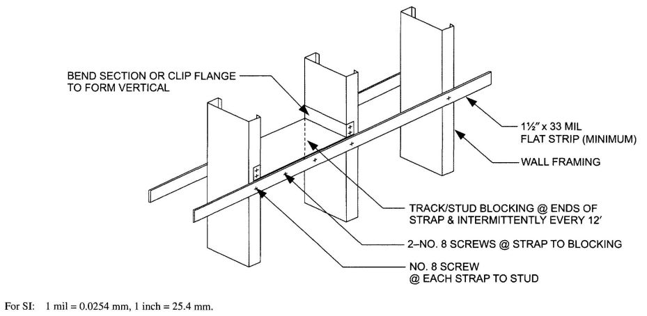
FIGURE R603.3.3(1)
STUD BRACING WITH STRAPPING ONLY
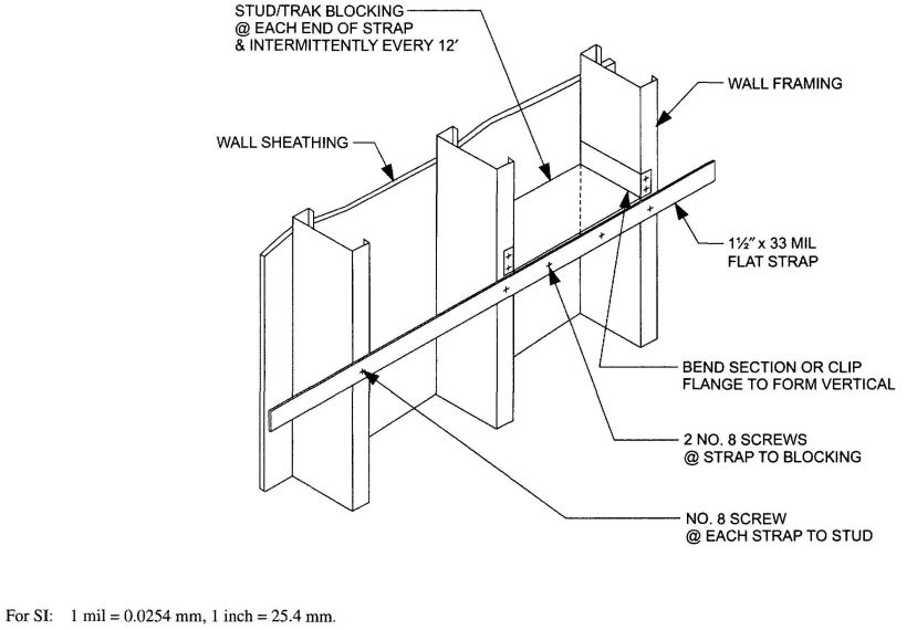
FIGURE R603.3.3(2)
STUD BRACING WITH STRAPPING AND SHEATHING MATERIAL
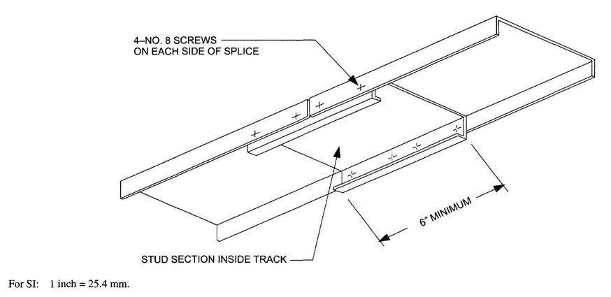
FIGURE R603.3.5 TRACK SPLICE
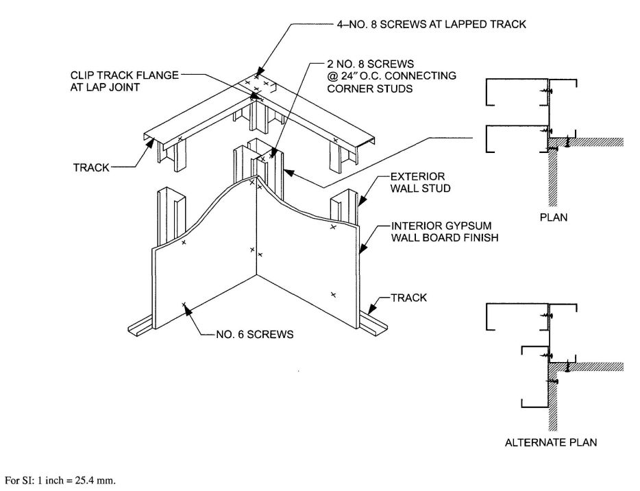
FIGURE R603.4 CORNER FRAMING
281| WIND SPEED | MEMBER SIZE | STUD SPACING (inches) | MINIMUM STUD THICKNESS (Mils) | |||
|---|---|---|---|---|---|---|
| Exp. B | Exp. C | 8-foot studs | 9-foot studs | 10-foot studs | ||
| For SI: 1 inch = 25.4, 1 foot = 304.8 mm, 1 mil = 0.0254 mm, 1 mile per hour =0.447 m/s, 1 pound per square foot = 0.0479 kPa, 1 ksi = 6.895 MPa. | ||||||
| a. Deflection criterion L/240. | ||||||
| b. Design load assumptions: | ||||||
| Ground snow load is 70 psf. | ||||||
| Roof and ceiling dead load is 12 psf. | ||||||
| Floor dead load is 10 psf. | ||||||
| Floor live load is 40 psf. | ||||||
| Attic dead load is 10 psf. | ||||||
| c. Building width is in the direction of horizontal framing members supported by the wall studs. | ||||||
| 85 mph | — | 350S162 | 16 | 33 | 33 | 33 |
| 24 | 33 | 33 | 33 | |||
| 550S162 | 16 | 33 | 33 | 33 | ||
| 24 | 33 | 33 | 33 | |||
| 90 mph | — | 350S162 | 16 | 33 | 33 | 33 |
| 24 | 33 | 33 | 33 | |||
| 550S162 | 16 | 33 | 33 | 33 | ||
| 24 | 33 | 33 | 33 | |||
| 100 mph | 85 mph | 350S162 | 16 | 33 | 33 | 33 |
| 24 | 33 | 33 | 33 | |||
| 550S162 | 16 | 33 | 33 | 33 | ||
| 24 | 33 | 33 | 33 | |||
| 110 mph | 90 mph | 350S162 | 16 | 33 | 33 | 33 |
| 24 | 33 | 33 | 33 | |||
| 550S162 | 16 | 33 | 33 | 33 | ||
| 24 | 33 | 33 | 43 | |||
| — | 100 mph | 350S162 | 16 | 33 | 33 | 33 |
| 24 | 33 | 33 | 54 | |||
| 550S162 | 16 | 33 | 33 | 33 | ||
| 24 | 33 | 33 | 33 | |||
| — | 110 mph | 350S162 | 16 | 33 | 43 | 43 |
| 24 | 43 | 54 | 54 | |||
| 550S162 | 16 | 33 | 33 | 33 | ||
| 24 | 33 | 33 | 43 | |||
| WIND SPEED | MEMBER SIZE | STUD SPACING (inches) | MINIMUM STUD THICKNESS (Mils) | |||
|---|---|---|---|---|---|---|
| Exp. B | Exp. C | 8-foot studs | 9-foot studs | 10-foot studs | ||
| For SI: 1 inch = 25.4, 1 foot = 304.8 mm, 1 mil = 0.0254 mm, 1 mile per hour = 0.447 m/s, 1 pound per square foot = 0.0479 kPa, 1 ksi = 6.895 MPa. | ||||||
| a. Deflection criterion L/240 | ||||||
| b. Design load assumptions: | ||||||
| Ground snow load is 70 psf. | ||||||
| Roof and ceiling dead load is 12 psf. | ||||||
| Floor dead load is 10 psf. | ||||||
| Floor live load is 40 psf. | ||||||
| Attic dead load is 10 psf. | ||||||
| c. Building width is in the direction of horizontal framing members supported by the wall studs. | ||||||
| 85 mph | — | 350S162 | 16 | 33 | 33 | 33 |
| 24 | 33 | 33 | 33 | |||
| 550S162 | 16 | 33 | 33 | 33 | ||
| 24 | 33 | 33 | 33 | |||
| 90 mph | — | 350S162 | 16 | 33 | 33 | 33 |
| 24 | 33 | 33 | 33 | |||
| 550S162 | 24 | 33 | 33 | 33 | ||
| 24 | 33 | 33 | 33 | |||
| 100 mph | 85 mph | 350S162 | 16 | 33 | 33 | 33 |
| 24 | 33 | 33 | 33 | |||
| 550S162 | 16 | 33 | 33 | 33 | ||
| 24 | 33 | 33 | 33 | |||
| 110 mph | 90 mph | 350S162 | 16 | 33 | 33 | 33 |
| 24 | 33 | 33 | 43 | |||
| 550S162 | 16 | 33 | 33 | 33 | ||
| 24 | 33 | 33 | 33 | |||
| — | 100 mph | 350S162 | 16 | 33 | 33 | 33 |
| 24 | 33 | 33 | 43 | |||
| 550S162 | 16 | 33 | 33 | 33 | ||
| 24 | 33 | 33 | 33 | |||
| — | 110 mph | 350S162 | 16 | 33 | 33 | 33 |
| 24 | 33 | 43 | 54 | |||
| 550S162 | 16 | 33 | 33 | 33 | ||
| 24 | 33 | 33 | 33 | |||
| WIND SPEED | MEMBER SIZE | STUD SPACING (inches) | MINIMUM STUD THICKNESS (Mils) | ||||||
|---|---|---|---|---|---|---|---|---|---|
| Exp. B | Exp. C | Stud Height, h (feet) | |||||||
| 10<h≤12 | 12<h≤14 | 14<h≤16 | 16<h≤18 | 18<h≤20 | 20<h≤22 | ||||
| For SI: 1 inch = 25.4, 1 foot = 304.8 mm, 1 mil = 0.0254 mm, 1 mile per hour = 0.447 m/s, 1 pound per square foot = 0.0479 kPa, 1 ksi = 6.895 MPa. | |||||||||
| a. Deflection criterion L/240. | |||||||||
| b. Design load assumptions: | |||||||||
| Ground snow load is 70 psf. | |||||||||
| Roof and ceiling dead load is 12 psf. | |||||||||
| Floor dead load is 10 psf. | |||||||||
| Floor live load is 40 psf. | |||||||||
| Attic dead load is 10 psf. | |||||||||
| c. Building width is in the direction of horizontal framing members supported by the wall studs. | |||||||||
| 85 mph | — | 350S162 | 16 | 33 | 43 | 54 | 97 | — | — |
| 24 | 43 | 54 | 97 | — | — | — | |||
| 550S162 | 16 | 33 | 33 | 33 | 43 | 43 | 54 | ||
| 24 | 33 | 33 | 43 | 54 | 68 | 97 | |||
| 90 mph | — | 350S162 | 16 | 33 | 43 | 68 | 97 | — | — |
| 24 | 43 | 68 | 97 | — | — | — | |||
| 550S1625 | 16 | 33 | 33 | 33 | 43 | 54 | 54 | ||
| 24 | 33 | 33 | 43 | 54 | 68 | 97 | |||
| 100 mph | 85 mph | 350S162 | 16 | 43 | 54 | 97 | — | — | — |
| 24 | 54 | 97 | — | — | — | — | |||
| 550S162 | 16 | 33 | 33 | 43 | 54 | 54 | 68 | ||
| 24 | 33 | 43 | 54 | 68 | 97 | 97 | |||
| 110 mph | 90 mph | 350S162 | 16 | 43 | 68 | — | — | — | — |
| 24 | 68 | — | — | — | — | — | |||
| 550S162 | 16 | 33 | 43 | 43 | 54 | 68 | 97 | ||
| 24 | 43 | 54 | 68 | 97 | 97 | — | |||
| — | 100 mph | 350S162 | 16 | 54 | 97 | — | — | — | — |
| 24 | 97 | — | — | — | — | — | |||
| 550S162 | 16 | 33 | 43 | 54 | 68 | 97 | — | ||
| 24 | 43 | 68 | 97 | 97 | — | — | |||
| — | 110 mph | 350S162 | 16 | 68 | 97 | — | — | — | — |
| 24 | 97 | — | — | — | — | — | |||
| 550S162 | 16 | 43 | 54 | 68 | 97 | 97 | — | ||
| 24 | 54 | 68 | 97 | — | — | — | |||
| WIND SPEED | MEMBER SIZE | STUD SPACING (inches) | MINIMUM STUD THICKNESS (Mils) | ||||||
|---|---|---|---|---|---|---|---|---|---|
| Exp. B | Exp. C | Stud Height, h (feet) | |||||||
| 10<h≤12 | 12<h≤14 | 14<h≤16 | 16<h≤18 | 18<h≤20 | 20<h≤22 | ||||
| For SI: 1 inch = 25.4, 1 foot = 304.8 mm, 1 mil = 0.0254 mm, 1 mile per hour = 0.447 m/s, 1 pound per square foot = 0.0479 kPa, 1 ksi = 6.895 MPa. | |||||||||
| a. Deflection criterion L/240. | |||||||||
| b. Design load assumptions: | |||||||||
| Ground snow load is 70 psf. | |||||||||
| Roof and ceiling dead load is 12 psf. | |||||||||
| Floor dead load is 10 psf. | |||||||||
| Floor live load is 40 psf. | |||||||||
| Floor live load is 40 psf. | |||||||||
| c. Building width is in the direction of horizontal framing members supported by the wall studs. | |||||||||
| 85 mph | — | 350S162 | 16 | 33 | 43 | 54 | 97 | — | — |
| 24 | 33 | 54 | 97 | — | — | — | |||
| 550S162 | 16 | 33 | 33 | 33 | 33 | 43 | 54 | ||
| 24 | 33 | 33 | 33 | 43 | 54 | 97 | |||
| 90 mph | — | 350S162 | 16 | 33 | 43 | 68 | 97 | — | — |
| 24 | 43 | 68 | 97 | — | — | — | |||
| 550S162 | 16 | 33 | 33 | 33 | 33 | 43 | 54 | ||
| 24 | 33 | 33 | 43 | 43 | 68 | 97 | |||
| 100 mph | 85 mph | 350S162 | 16 | 33 | 54 | 97 | — | — | — |
| 24 | 54 | 97 | — | — | — | — | |||
| 550S162 | 16 | 33 | 33 | 33 | 43 | 54 | 68 | ||
| 24 | 33 | 33 | 43 | 54 | 97 | 97 | |||
| 110 mph | 90 mph | 350S162 | 16 | 43 | 68 | — | — | — | — |
| 24 | 68 | — | — | — | — | — | |||
| 550S162 | 16 | 33 | 33 | 43 | 54 | 68 | 97 | ||
| 24 | 33 | 43 | 54 | 68 | 97 | — | |||
| — | 100 mph | 350S162 | 16 | 54 | 97 | — | — | — | — |
| 24 | 97 | — | — | — | — | — | |||
| 550S162 | 16 | 33 | 33 | 43 | 54 | 97 | — | ||
| 24 | 43 | 54 | 54 | 97 | — | — | |||
| — | 110 mph | 350S162 | 16 | 54 | 97 | — | — | — | — |
| 24 | 97 | — | — | — | — | — | |||
| 550S162 | 16 | 33 | 43 | 54 | 68 | 97 | — | ||
| 24 | 43 | 54 | 68 | 97 | — | — | |||
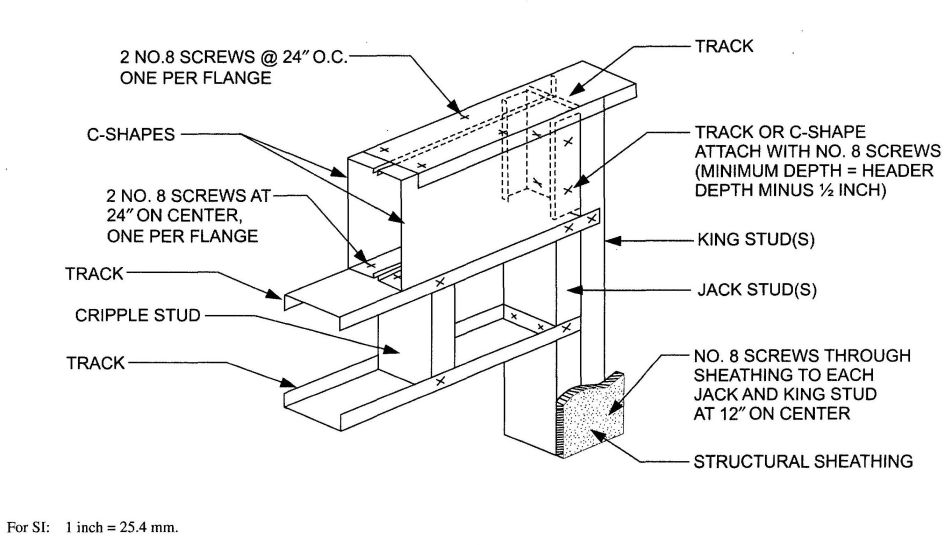
FIGURE R603.6(1)
BOX BEAM HEADER
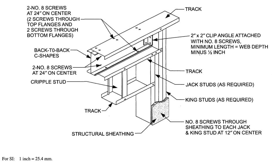
FIGURE 601.6(2)
BACK-TO-BACK HEADER
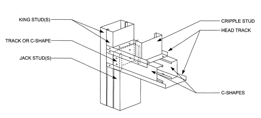
FIGURE R603.6.1(1)
BOX BEAM HEADER IN GABLE ENDWALL
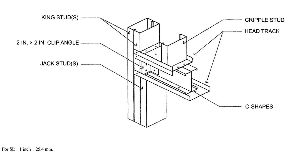
FIGURE R603.6.1(2)
BACK-TO-BACK HEADER IN GABLE ENDWALL
| MEMBER DESIGNATION | GROUND SNOW LOAD(20 psf) | GROUND SNOW LOAD(30 psf) | ||||||||
|---|---|---|---|---|---|---|---|---|---|---|
| Building widthc (feet) | Building widthc (feet) | |||||||||
| 24 | 28 | 32 | 36 | 40 | 24 | 28 | 32 | 36 | 40 | |
| For SI: 1 inch = 25.4 mm, 1 foot=304.8 mm, 1 pound per square foot=0.0479kpa, 1 pound per square inch = 6.895 kPa. | ||||||||||
| a. Deflection criterion: L/360 for live loads, L/240 for total loads. | ||||||||||
| b. Design load assumptions: | ||||||||||
| Roof/Ceiling dead load is 12 psf. | ||||||||||
| Attic dead load is 10 psf. | ||||||||||
| c. Building width is in the direction of horizontal framing members supported by the header | ||||||||||
| 2-350S162-33 | 3′;-3″ | 2′;-8″ | 2′;-2″ | — | — | 2′;-8″ | 2′;-2″ | — | — | — |
| 2-350S162-43 | 4′;-2″ | 3′;-9″ | 3′;-4″ | 2′;-11″ | 2′;-7″ | 3′;-9″ | 3′;-4″ | 2′;-11″ | 2′;-7″ | 2′;-2″ |
| 2-350S162-54 | 5′;-0″ | 4′;-6″ | 4′;-1″ | 3′;-8″ | 3′;-4″ | 4′;-6″ | 4′;-1″ | 3′;-8″ | 3′;-3″ | 3′;-0″ |
| 2-350S162-68 | 5′;-7″ | 5′;-1″ | 4′;-7″ | 4′;-3″ | 3′;-10″ | 5′;-1″ | 4′;-7″ | 4′;-2″ | 3′;-10″ | 3′;5″ |
| 2-350S162-97 | 7′;-1″ | 6′;-6″ | 6′;-1″ | 5′;-8″ | 5′;-3″ | 6′;-7″ | 6′;-1″ | 5′;-7″ | 5′;-3″ | 4′;-11″ |
| 2-550S162-33 | 4′;-8″ | 4′;-0″ | 3′;-6″ | 3′;-0″ | 2′;-6″ | 4′;-1″ | 3′;-6″ | 3′;-0″ | 2′;-6″ | — |
| 2-550S162-43 | 6′;-0″ | 5′;-4″ | 4′;-10″ | 4′;-4″ | 3′;-11″ | 5′;-5″ | 4′;-10″ | 4′;-4″ | 3′;-10″ | 3′;-5″ |
| 2-550S162-54 | 7′;-0″ | 6′;-4″ | 5′;-9″ | 5′;-4″ | 4′;-10″ | 6′;-5″ | 5′;-9″ | 5′;-3″ | 4′;-10″ | 4′;-5″ |
| 2-550S162-68 | 8′;-0″ | 7′;-4″ | 6′;-9″ | 6′;-3″ | 5′;-10″ | 7′;-5″ | 6′;-9″ | 6′;-3″ | 5′;-9″ | 5′;-4″ |
| 2-550S162-97 | 9′;-11″ | 9′;-2″ | 8′;-6″ | 8′;-0″ | 7′;-6″ | 9′;-3″ | 8′;-6″ | 8′;-0″ | 7′;-5″ | 7′;-0″ |
| 2-800S162-33 | 4′;-5″ | 3′;-11″ | 3′;-5″ | 3′;-1″ | 2′;-10″10 | 3′;-11″ | 3′;-6″ | 3′;-1″ | 2′;-9″ | 2′;-3″ |
| 2-800S162-43 | 7′;-3″ | 6′;-7″ | 5′;-11″ | 5′;-10″ | 4′;-10″ | 6′;-7″ | 5′;-11″ | 5′;-4″ | 4′;-9″ | 4′;-3″ |
| 2-800S162-54 | 8′;-10″ | 8′;-0″ | 7′;-4″ | 6′;-9″ | 6′;-2″ | 8′;-1″ | 7′;-4″ | 6′;-8″ | 6′;-1″ | 5′;-7″ |
| 2-800S162-68 | 10′;-5″ | 9′;-7″ | 8′;-10″ | 8′;-2″ | 7′;-7″ | 9′;-8″ | 8′;-10″ | 8′;-1″ | 7′;-6″ | 7′;-0″ |
| 2-800S162-97 | 13′;-1″ | 12′;-1″ | 11′;-3″ | 10′;-7″ | 10′;-0″ | 12′;-2″ | 11′;-4″ | 10′;-6″ | 10′;-0″ | 9′;-4″ |
| 2-1000S162-43 | 7′;-10″ | 6′;-10″ | 6′;-1″ | 5′;-6″ | 5′;-0″ | 6′;-11″ | 6′;-1″ | 5′;-5″ | 4′;-11″ | 4′;-6″ |
| 2-1000S162-54 | 10′;-0″ | 9′;-1″ | 8′;-3″ | 7′;-7″ | 7′;-0″ | 9′;-2″ | 8′;-4″ | 7′;-7″ | 6′;-11″ | 6′;-4″ |
| 2-1000S162-68 | 11′;-11″ | 10′;-11″ | 10′;-1″ | 9′;-4″ | 8′;-8″ | 11′;-0″ | 10′;-1″ | 9′;-3″ | 8′;-7″ | 8′;-0″ |
| 2-1000S162-97 | 15′;-3″ | 14′;-3″ | 13′;-5″ | 12′;-6″ | 11′;-10″ | 14′;-4″ | 13′;-5″ | 12′;-6″ | 11′;-9″ | 11′;-0″ |
| 2-1200S162-54 | 11′;-1″ | 10′;-0″ | 9′;-2″ | 8′;-5″ | 7′;-9″ | 10′;-1″ | 9′;-2″ | 8′;-4″ | 7′;-7″ | 7′;-0″ |
| 2-1200S162-68 | 13′;-3″ | 12′;-1″ | 11′;-2″ | 10′;-4″ | 9′;-7″ | 12′;-3″ | 11′;-2″ | 10′;-3″ | 9′;-6″ | 8′;-10″ |
| 2-1200S162-97 | 16′;-8″ | 15′;-7″ | 14′;-8″ | 13′;-11″ | 13′;-3″ | 15′;-8″ | 14′;-8″ | 13′;-11″ | 13′;-2″ | 12′;-6″ |
| MEMBER DESIGNATION | GROUND SNOW LOAD (20 psf) | GROUND SNOW LOAD (30 psf) | |||||||||||||
|---|---|---|---|---|---|---|---|---|---|---|---|---|---|---|---|
| Building widthc (feet) | Building widthc (feet) | ||||||||||||||
| 24 | 28 | 32 | 36 | 40 | 24 | 28 | 32 | 36 | 40 | ||||||
| For SI: 1 inch = 25.4 mm, 1 foot = 304.8 mm, 1 pound per square foot=0.0479 kPa, 1 pound per square inch = 6.895 kPa. | |||||||||||||||
| a. Deflection criterion: L/360 for live loads, L/240 for total loads. | |||||||||||||||
| b. Design load assumptions: | |||||||||||||||
| Roof/Ceiling dcad load is 12 psf. | |||||||||||||||
| Attic dead load is 10 psf. | |||||||||||||||
| c. Building width is in the direction of horizontal framing members supported by the header | |||||||||||||||
| 2-350S162-33 | 4′;-4″ | 3′;-11″ | 3′;-6″ | 3′;-2″ | 2′;-10″ | 3′;-11″ | 3′;-6″ | 3′;-1″ | 2′;-9″ | 2′;-5″ | |||||
| 2-350S162-43 | 5′;-6″ | 5′;-0″ | 4′;-7″ | 4′;-2″ | 3′;-10″ | 5′;-0″ | 4′;-7″ | 4′;-2″ | 3′;-10″ | 3′;-6″ | |||||
| 2-350S162-54 | 6′;-2″ | 5′;-10″ | 5′;-8″ | 5′;-3″ | 4′;-10″ | 5′;-11″ | 5′;-8″ | 5′;-2″ | 4′;-10″ | 4′;-6″ | |||||
| 2-350S162-68 | 6′;-7″ | 6′;-3″ | 6′;-0″ | 5′;-10″ | 5′;-8″ | 6′;-4″ | 6′;-1″ | 5′;-10″ | 5′;-8″ | 5′;-6″ | |||||
| 2-350S162-97 | 7′;-3″ | 6′;-1″ | 6′;-8″ | 6′;-5″ | 6′;-3″ | 7′;-0″ | 6′;-8″ | 6′;-5″ | 6′;-3″ | 6′;-0″ | |||||
| 2-550S162-33 | 6′;-2″ | 5′;-6″ | 5′;-0″ | 4′;-7″ | 4′;-2″ | 5′;-7″ | 5′;-0″ | 4′;-6″ | 4′;-1″ | 3′;-8″ | |||||
| 2-550S162-43 | 7′;-9″ | 7′;-2″ | 6′;-7″ | 6′;-1″ | 5′;-8″ | 7′;-3″ | 6′;-7″ | 6′;-1″ | 5′;-7″ | 5′;-2″ | |||||
| 2-550S162-54 | 8′;-9″ | 8′;-5″ | 8′;-1″ | 7′;-9″ | 7′;-3″ | 8′;-6″ | 8′;-1″ | 7′;-8″ | 7′;-2″ | 6′;-8″ | |||||
| 2-550S162-68 | 9′;-5″ | 9′;-0″ | 8′;-8″ | 8′;-4″ | 8′;-1″ | 9′;-1″ | 8′;-8″ | 8′;-4″ | 8′;-1″ | 7′;-10″ | |||||
| 2-550S162-97 | 10′;-5″ | 10′;-0″ | 9′;-7″ | 9′;-3″ | 9′;-0″ | 10′;-0″ | 9′;-7″ | 9′;-3″ | 8′;-11″ | 8′;-8″ | |||||
| 2-800S162-33 | 4′;-5″ | 3′;-11″ | 3′;-5″ | 3′;-1″ | 2′;-10″ | 3′;-11″ | 3′;-6″ | 3′;-1″ | 2′;-9″ | 2′;-6″ | |||||
| 2-800S162-43 | 9′;-1″ | 8′;-5″ | 7′;-8″ | 6′;-11″ | 6′;-3″ | 8′;-6″ | 7′;-8″ | 6′;-10″ | 6′;-2″ | 5′;-8″ | |||||
| 2-800S162-54 | 10′;-10″ | 10′;-2″ | 9′;-7″ | 9′;-0″ | 8′;-5″ | 10′;-2″ | 9′;-7″ | 8′;-11″ | 8′;-4″ | 7′;-9″ | |||||
| 2-800S162-68 | 12′;-8″ | 11′;-10″ | 11′;-2″ | 10′;-7″ | 10′;-1″ | 11′;-11″ | 11′;-2″ | 10′;-7″ | 10′;-0″ | 9′;-6″ | |||||
| 2-800S162-97 | 14′;-2″ | 13′;-6″ | 13′;-0″ | 12′;-7″ | 12′;-2″ | 13′;-8″ | 13′;-1″ | 12′;-7″ | 12′;-2″ | 11′;-9″ | |||||
| 2-1000S162-43 | 7′;-10 | 6′;-10″ | 6′;-1″ | 5′;-6″ | 5′;-0″ | 6′;-11″ | 6′;-1″ | 5′;-5″ | 4′;-11″ | 4′;-6″ | |||||
| 2-1000S162-54 | 12′;-3″ | 11′;-5″ | 10″-9′; | 10′;-2″ | 9′;-6″ | 11′;-6″ | 10′;-9″ | 10′;-1″ | 9′;-5″ | 8′;-9″ | |||||
| 2-1000S162-68 | 14′;-5″ | 13′;-5″ | 12′;-8″ | 12′;-0″ | 11′;-6″ | 13′;-6″ | 12′;-8″ | 12′;-0″ | 11′;-5″ | 10′;-10″ | |||||
| 2-1000S162-97 | 17′;-1″ | 16′;-4″ | 15′;-8″ | 14′;-11″ | 14′;-3″ | 16′;-5″ | 15′;-9″ | 14′;-10″ | 14′;-1″ | 13′;-6″ | |||||
| 2-1200S162-54 | 12′;-11″ | 11′;-3″ | 10′;-0″ | 9′;-0″ | 8′;-2″ | 11′;-5″ | 10′;-0″ | 9′;-0″ | 8′;-1″ | 7′;-4″ | |||||
| 2-1200S162-68 | 15′;-11″ | 14′;-10″ | 14′;-10″ | 13′;-4″ | 12′;-8″ | 15′;-0″ | 14′;-0″ | 13′;-3″ | 12′;-7″ | 11′;-11″ | |||||
| 2-1200S162-97 | 19′;-11″ | 18′;-7″ | 17′;-6″ | 16′;-8″ | 15′;-10″ | 18′;-9″ | 17′;-7″ | 16′;-7″ | 15′;-9″ | 15′;-0″ | |||||
| MEMBER DESIGNATION | GROUND SNOW LOAD (20 psf) | GROUND SNOW LOAD (30 psf) | ||||||||
|---|---|---|---|---|---|---|---|---|---|---|
| Building widthc (feet) | Building widthc (feet) | |||||||||
| 24 | 28 | 32 | 36 | 40 | 24 | 28 | 32 | 36 | 40 | |
| For SI: 1 inch = 25.4 mm, 1 foot = 304.8 mm, 1 pound per square foot=0.0479 kPa. 1 pound per square inch = 6.895 kPa. | ||||||||||
| a. Deflection criterion: L/360 for live loads, L/240 for total loads. | ||||||||||
| b. Design load assumptions: | ||||||||||
| Roof/Ceiling dead load is 12 psf. | ||||||||||
| Attic dead load is 10 psf. | ||||||||||
| c. Building width is in the direction of horizontal framing members supported by the header | ||||||||||
| 2-350S162-33 | — | — | — | — | — | — | — | — | — | — |
| 2-350S162-43 | 2′;-4″ | — | — | — | — | — | — | — | — | — |
| 2-350S162-54 | 3′;-1″ | 2′;-8″ | 2′;-3″ | — | — | 2′;-1″ | — | — | — | — |
| 2-350S162-68 | 3′;-7″ | 3′;-2″ | 2′;-8″ | 2′;-3″ | — | 2′;-6″ | — | — | — | — |
| 2-350S162-97 | 5′;-1″ | 4′;-7″ | 4′;-3″ | 3′;-11″ | 3′;-7″ | 4′;-1″ | 3′;-8″ | 3′;-4″ | 3′;-0″ | 2′;-8″ |
| 2-550S162-33 | 2′;-2″ | — | — | — | — | — | — | — | — | — |
| 2-550S162-43 | 3′;-8″ | 3′;-1″ | 2′;-6″ | — | — | 2′;-3″ | — | — | — | — |
| 2-550S162-54 | 4″-7′; | 4′;-0″ | 3′;-6″ | 3″0″ | 2′;-6″ | 3′;-3″ | 2′;-8″ | 2′;-1″ | — | — |
| 2-550S162-68 | 5′;-6″ | 4′;-11″ | 4′;-5″ | 3′;-11″ | 3′;-6″ | 4′;-3″ | 3′;-8″ | 3′;-1″ | 2′;-7″ | 2′;-1″ |
| 2-550S162-97 | 7′;-3″ | 6′;-7″ | 6′;-1″ | 5′;-8″ | 5′;-3″ | 5′;-11″ | 5′;-4″ | 4′;-11″ | 4′;-6″ | 4′;-1″ |
| 2-800S162-33 | 2-7 | — | — | — | — | — | — | — | — | — |
| 2-800S162-43 | 4′;-6″ | 3′;-9″ | 3′;-1″ | 2′;-5″ | — | 2′;-10″ | — | — | — | — |
| 2-800S162-54 | 5′;-10″ | 5′;-1″ | 4′;-6″ | 3′;-11″ | 3′;-4″ | 4′;-3″ | 3′;-6″ | 2′;-9″ | — | — |
| 2-800S162-68 | 7′;-2″ | 6′;-6″ | 5′;-10″ | 5′;-3″ | 4′;-8″ | 5′;-7″ | 4′;-10″ | 4′;-2″ | 3′;-7″ | 2′;-11″ |
| 2-800S162-97 | 9′;-7″ | 8′;-9″ | 8′;-2″ | 7′;-7″ | 7′;-0″ | 7′;-11″ | 7′;-2″ | 6′;-7″ | 6′;-0″ | 5′;-7″ |
| 2-1000S162-43 | 4′;-8″ | 4′;-1″ | 3′;-6″ | 2′;-9″ | — | 3′;-3″ | 2′;-2″ | — | — | — |
| 2-1000S162-54 | 6′;-7″ | 5′;-10″ | 5′;-1″ | 4′;-5″ | 3′;-9″ | 4′;-10″ | 4′;-0″ | 3′;-2″ | 2′;-3″ | — |
| 2-1000S162-68 | 8′;-3″ | 7′;-5″ | 6′;-8″ | 6′;-0″ | 5′;-5″ | 6′;-5″ | 5′;-7″ | 4′;-9″ | 4′;-1″ | 3′;-5″ |
| 2-1000S162-97 | 11′;-4″ | 10″-5′; | 9″-8′; | 9″-0″ | 8′;-5″ | 9′;-5″ | 8′;-6″ | 7′;-10″ | 7′;-2″ | 6′;-7″ |
| 2-1200S162-54 | 7′;-3″ | 6′;-5″ | 5′;-7″ | 4′;-10″ | 4′;-2″ | 5′;-4″ | 4′;-4″ | 3′;-5″ | 2′;-5″ | — |
| 2-1200S162-68 | 9′;-2″ | 8′;-2″ | 7′;-5″ | 6′;-8″ | 6′;-0″ | 7′;-1″ | 6′;-2″ | 5′;-4″ | 4′;-6″ | 3′;-9″ |
| 2-1200S162-97 | 12′;-10″ | 11′;-9″ | 10′;-11″ | 10′;-2″ | 9′;-6″ | 10′;-7″ | 9′;-8″ | 8′;-10″ | 8′;-2″ | 7′;-6″ |
| MEMBER DESIGNATION | GROUND SNOW LOAD (50 psf) | GROUND SNOW LOAD (70 psf) | ||||||||
|---|---|---|---|---|---|---|---|---|---|---|
| Building widthc (feet) | Building widthc (feet) | |||||||||
| 24 | 28 | 32 | 36 | 40 | 24 | 28 | 32 | 36 | 40 | |
| For SI: 1 inch = 25.4 mm, 1 foot = 304.8 mm, 1 pound per square foot = 0.0479 kPa, 1 pound per square inch = 6.895 kPa. | ||||||||||
| a. Deflection criterion: L/360 for live loads, L/240 for total loads. | ||||||||||
| b. Design load assumptions: | ||||||||||
| Roof/Ceiling dead load is 12 psf. | ||||||||||
| Attic dead load is 10 psf. | ||||||||||
| c. Building width is in the direction of horizontal framing members supported by the header. | ||||||||||
| 2-350S162-33 | 2′;-7″ | 2′;-2″ | — | — | — | — | — | — | — | — |
| 2-350S162-43 | 3′;-8″ | 3′;-3″ | 2′;-10″ | 2′;-6″ | 2′;-1″ | 2′;-8″ | 2′;-3″ | — | — | — |
| 2-350S162-54 | 4′;-8″ | 4′;-2″ | 3′;-9″ | 3′;-5″ | 3′;-1″ | 3′;-7″ | 3′;-2″ | 2′;-9″ | 2′;-5″ | 2′;-0″ |
| 2-350S162-68 | 5′;-7″ | 5′;-2″ | 4′;-9″ | 4′;-4″ | 3′;-11″ | 4′;-7″ | 4′;-1″ | 3′;-7″ | 3′;-2″ | 2′;-10″ |
| 2-350S162-97 | 6′;-2″ | 5′;-11″ | 5′;-8″ | 5′;-6″ | 5′;-4″ | 5′;-8″ | 5′;-5″ | 5′;-3″ | 4′;-11″ | 4′;-7″ |
| 2-550S162-33 | 3′;-11″ | 3′;-4″ | 2′;-10″ | 2′;-4″ | — | 2′;-7″ | — | — | — | — |
| 2-550S162-43 | 5′;-4″ | 4′;-10″ | 4′;-4″ | 3′;-10″ | 3′;-5″ | 4′;-2″ | 3′;-7″ | 3′;-1″ | 2′;-7″ | 2′;-1″ |
| 2-550S162-54 | 6′;-11″ | 6′;-3″ | 5′;-9″ | 5′;-3″ | 4′;-9″ | 5′;-6″ | 4′;-11″ | 4′;-5″ | 3′;-11″ | 3′;-5″ |
| 2-550S162-68 | 8′;-0″ | 7′;-6″ | 6′;-11″ | 6′;-5″ | 5′;-11″ | 6′;-9″ | 6′;-1″ | 5′;-6″ | 5′;-0″ | 4′;-7″ |
| 2-550S162-97 | 8′;-11″ | 8′;-6″ | 8′;-2″ | 7′;-11″ | 7′;-8″ | 8′;-1″ | 7′;-9″ | 7′;-6″ | 7′;-1″ | 6′;-7″ |
| 2-800S162-33 | 2′;-8″ | 2′;-4″ | 2′;-1″ | 1′;-11″ | 1′;-9″ | 2′;-0″ | 1′;-9″ | — | — | — |
| 2-800S162-43 | 5′;-10″ | 5′;-2″ | 4′;-7″ | 4′;-2″ | 3′;-10″ | 4′;-5″ | 3′;-11″ | 3′;-6″ | 3′;-0″ | 2′;-6″ |
| 2-800S162-54 | 8′;-0″ | 7′;-3″ | 6′;-8″ | 6′;-1″ | 5′;-7″ | 6′;-5″ | 5′;-9″ | 5′;-1″ | 4′;-7″ | 4′;-0″ |
| 2-800S162-68 | 9′;-9″ | 9′;-0″ | 8′;-3″ | 7′;-8″ | 7′;-1″ | 8′;-0″ | 7′;-3″ | 6′;-7″ | 6′;-0″ | 5′;-6″ |
| 2-800S162-97 | 12′;-1″ | 11′;-7″ | 11′;-2″ | 10′;-8″ | 10′;-2″ | 11′;-0″ | 10′;-4″ | 9′;-9″ | 9′;-2″ | 8′;-7″ |
| 2-1000S162-43 | 4′;-8″ | 4′;-1″ | 3′;-8″ | 3′;-4″ | 3′;-0″ | 3′;-6″ | 3′;-1″ | 2′;-9″ | 2′;-6″ | 2′;-3″ |
| 2-1000S162-54 | 9′;-1″ | 8′;-2″ | 7′;-3″ | 6′;-7″ | 6′;-0″ | 7′;-0″ | 6′;-2″ | 5′;-6″ | 5′;-0″ | 4′;-6″ |
| 2-1000S162-68 | 11′;-1″ | 10′;-2″ | 9′;-5″ | 8′;-8″ | 8′;-1″ | 9′;-1″ | 8′;-3″ | 7′;-6″ | 6′;-10″ | 6′;-3″ |
| 2-1000S162-97 | 13′;-9″ | 12′;-11″ | 12′;-2″ | 11′;-7″ | 11′;-1″ | 11′;-11″ | 11′;-3″ | 10′;-7″ | 9′;-11″ | 9′;-4″ |
| 2-1200S162-54 | 7′;-8″ | 6′;-9″ | 6′;-1″ | 5′;-6″ | 5′;-0″ | 5′;-10″ | 5′;-1″ | 4′;-7″ | 4′;-1″ | 3′;-9″ |
| 2-1200S162-68 | 12′;-3″ | 11′;-3″ | 10′;-4″ | 9′;-7″ | 8′;-11″ | 10′;-1″ | 9′;-1″ | 8′;-3″ | 7′;-6″ | 6′;-10″ |
| 2-1200S162-97 | 15′;-4″ | 14′;-5″ | 13′;-7″ | 12′;-11″ | 12′;-4″ | 13′;-4″ | 12′;-6″ | 11′;-10″ | 11′;-1″ | 10′;-5″ |
| MEMBER DESIGNATION | GROUND SNOW LOAD (50 psf) | GROUND SNOW LOAD (70 psf) | ||||||||
|---|---|---|---|---|---|---|---|---|---|---|
| Building widthc (feet) | Building widthc (feet) | |||||||||
| 24 | 28 | 32 | 36 | 40 | 24 | 28 | 32 | 36 | 40 | |
| For SI: 1 inch = 25.4 mm, 1 foot = 304.8 mm, 1 pound per square foot = 0.0479kPa, 1 pound per square inch = 6.895 kPa. | ||||||||||
| a. Deflection criterion: L/360 for live loads, L/240 for total loads. | ||||||||||
| b. Design load assumptions: | ||||||||||
| Second floor dead load is 10 psf. | ||||||||||
| Roof/Ceiling dead load is 12 psf. | ||||||||||
| Second floor live load is 30 psf. | ||||||||||
| Attic dead load is 10 psf. | ||||||||||
| c. Building width is in the direction of horizontal framing members supported by the header. | ||||||||||
| 2-350S162-33 | — | — | — | — | — | — | — | — | — | — |
| 2-350S162-43 | 2′;-2″ | — | — | — | — | 2′;-1″ | — | — | — | — |
| 2-350S162-54 | 2′;-11″ | 2′;-5″ | — | — | — | 2′;-10″ | 2′;-4″ | — | — | — |
| 2-350S162-68 | 3′;-8″ | 3′;-2″ | 2′;-9″ | 2′;-4″ | — | 3′;-7″ | 3′;-1″ | 2′;-8″ | 2′;-3″ | — |
| 2-350S162-97 | 4′;-11″ | 4′;-5″ | 4′;-2″ | 3′;-8″ | 3′;-5″ | 4′;-10″ | 4′;-5″ | 4′;-0″ | 3′;-8″ | 3′;-4″ |
| 2-550S162-33 | — | — | — | — | — | — | — | — | — | — |
| 2-550S162-43 | 3′;-5″ | 2′;-9″ | 2′;-1″ | — | — | 3′;-3″ | 2′;-7″ | — | — | — |
| 2-550S162-54 | 4′;-4″ | 3′;-9″ | 3′;-2″ | 2′;-7″ | 2′;-1″ | 4′;-3″ | 3′;-7″ | 3′;-1″ | 2′;-6″ | — |
| 2-550S162-68 | 5′;-3″ | 4′;-8″ | 4′;-1″ | 3′;-7″ | 3′;-2″ | 5′;-2″ | 4′;-7″ | 4′;-0″ | 3′;-6″ | 3′;-1″ |
| 2-550S162-97 | 7′;-0″ | 6′;-5″ | 5′;-10″ | 5′;-5″ | 5′;-0″ | 6′;-11″ | 6′;-4″ | 5′;-9″ | 5′;-4″ | 4′;-11″ |
| 2-800S162-33 | 2′;-1″ | — | — | — | — | — | — | — | — | — |
| 2-800S162-43 | 4′;-2″ | 3′;-4″ | 2′;-7″ | — | — | 4′;-0″ | 3′;-3″ | 2′;-5″ | — | — |
| 2-800S162-54 | 5′;-6″ | 4′;-9″ | 4′;-1″ | 3′;-5″ | 2′;-9″ | 5′;-5″ | 4′;-8″ | 3′;-11″ | 3′;-3″ | 2′;-8″ |
| 2-800S162-68 | 6′;-11″ | 6′;-2″ | 5′;-5″ | 4′;-10″ | 4′;-3″ | 6′;-9″ | 6′;-0″ | 5′;-4″ | 4′;-8″ | 4′;-1″ |
| 2-800S162-97 | 9′;-4″ | 8′;-6″ | 7′;-10″ | 7′;-3″ | 6′;-8″ | 9′;-2″ | 8′;-4″ | 7′;-8″ | 7′;-1″ | 6′;-7″ |
| 2-1000S162-43 | 4′;-4″ | 3′;-9″ | 2′;-11″ | — | — | 4′;-3″ | 3′;-8″ | 2′;-9″ | — | — |
| 2-1000S162-54 | 6′;-3″ | 5′;-5″ | 4′;-7″ | 3′;-11″ | 3′;-2″ | 6′;-1″ | 5′;-3″ | 4′;-6″ | 3′;-9″ | 3′;-0″ |
| 2-1000S162-68 | 7′;-11″ | 7′;-0″ | 6′;-3″ | 5′;-6″ | 4′;-10″ | 7′;-9″ | 6′;-10″ | 6′;-1″ | 5′;-4″ | 4′;-9″ |
| 2-1000S162-97 | 11′;-0″ | 10′;-1″ | 9′;-3″ | 8′;-7″ | 8′;-0″ | 10′;-11″ | 9′;-11″ | 9′;-2″ | 8′;-5″ | 7′;-10″ |
| 2-1200S162-54 | 6′;-11″ | 5′;-11″ | 5′;-1″ | 4′;-3″ | 3′;-5″ | 6′;-9″ | 5′;-9″ | 4′;-11″ | 4′;-1″ | 3′;-3″ |
| 2-1200S162-68 | 8′;-9″ | 7′;-9″ | 6′;-11″ | 6′;-1″ | 5′;-4″ | 8′;-7″ | 7′;-7″ | 6′;-9″ | 5′;-11″ | 5′;-3″ |
| 2-1200S162-97 | 12′;-4″ | 11′;-5″ | 10′;-6″ | 9′;-8″ | 9′;-0″ | 12′;-3″ | 11′;-3″ | 10′;-4″ | 9′;-6″ | 8′;-10″ |
| MEMBER DESIGNATION | GROUND SNOW LOAD (50 psf) | GROUND SNOW LOAD (70 psf) | ||||||||
|---|---|---|---|---|---|---|---|---|---|---|
| Building widthc (feet) | Building widthc (feet) | |||||||||
| 24 | 28 | 32 | 36 | 40 | 24 | 28 | 32 | 36 | 40 | |
| For SI: 1 inch = 25.4 mm, 1 foot = 304.8 mm, 1 pound per square foot = 0.0479kPa, 1 pound per square inch = 6.895kPa. | ||||||||||
| a. Deflection criterion: L/360 for live loads, L/240 for total loads. | ||||||||||
| b. Design load assumptions: | ||||||||||
| Second floor dead load is 10 psf. | ||||||||||
| Roof/ceiling dead load is 12 psf. | ||||||||||
| Second floor live load is 30 psf. | ||||||||||
| Attic live load is 10 psf. | ||||||||||
| c. Building width is in the direction of horizontal framing members supported by the header | ||||||||||
| 2-350S162-33 | 2′;-4″ | — | — | — | — | 2′;-3″ | — | — | — | — |
| 2-350S162-43 | 3′;-4″ | 2′;-11″ | 2′;-6″ | 2′;-1″ | — | 3′;-3″ | 2′;-10″ | 2′;-5″ | 2′;-0″ | — |
| 2-350S162-54 | 4′;-4″ | 3′;-10″ | 3′;-5″ | 3′;-1″ | 2′;-9″ | 4′;-3″ | 2′;-9″ | 3′;-4″ | 3′;-0″ | 2′;-8″ |
| 2-350S162-68 | 5′;-0″ | 4′;-9″ | 4′;-7″ | 4′;-2″ | 3′;-9″ | 4′;-11″ | 4′;-8″ | 4′;-6″ | 4′;-1″ | 3′;-9″ |
| 2-350S162-97 | 5′;-6″ | 5′;-3″ | 5′;-1″ | 4′;-11″ | 2′;-9″ | 5′;-5″ | 5′;-2″ | 5′;-0″ | 4′;-10″ | 4′;-8″ |
| 2-550S162-33 | 3′;-6″ | 2′;-11″ | 2′;-4″ | — | — | 3′;-5″ | 2′;-10″ | 2′;-3″ | — | — |
| 2-550S162-43 | 5′;-0″ | 4′;-5″ | 3′;-11″ | 3′;-5″ | 3′;-0″ | 4′;-11″ | 4′;-4″ | 3′;-10″ | 3′;-4″ | 2′;-11″ |
| 2-550S162-54 | 6′;-6″ | 5′;-10″ | 5′;-3″ | 4′;-9″ | 4′;-4″ | 6′;-4″ | 5′;-9″ | 5′;-2″ | 4′;-8″ | 4′;-3″ |
| 2-550S162-68 | 7′;-2″ | 6′;-10″ | 6′;-5″ | 5′;-11″ | 5′;-6″ | 7′;-0″ | 6′;-9″ | 6′;-4″ | 5′;-10″ | 5′;-4″ |
| 2-550S162-97 | 7′;-11″ | 7′;-7″ | 7′;-3″ | 7′;-0″ | 6′;-10″ | 7′;-9″ | 7′;-5″ | 7′;-2″ | 6′;-11″ | 6′;-9″ |
| 2-800S162-33 | 2′;-5″ | 2′;-2″ | 1′;-11″ | 1′;-9″ | — | 2′;-5″ | 2′;-1″ | 1′;-10″ | 1′;-8″ | — |
| 2-800S162-43 | 5′;-5″ | 4′;-9″ | 4′;-3″ | 3′;-9″ | 3′;-5″ | 5′;-3″ | 4′;-8″ | 4′;-1″ | 3′;-9″ | 3′;-5″ |
| 2-800S162-54 | 7′;-6″ | 6′;-9″ | 6′;-2″ | 5′;-7″ | 5′;-0″ | 7′;-5″ | 6′;-8″ | 6′;-0″ | 5′;-5″ | 4′;-11″ |
| 2-800S162-68 | 9′;-3″ | 8′;-5″ | 7′;-8″ | 7′;-1″ | 6′;-6″ | 9′;-1″ | 8′;-3″ | 7′;-7″ | 7′;-0″ | 6′;-5″ |
| 2-800S162-97 | 10′;-9″ | 10′;-3″ | 9′;-11″ | 9′;-7″ | 9′;-3″ | 10′;-7″ | 10′;-1″ | 9′;-9″ | 9′;-5″ | 9′;-1″ |
| 2-1000S162-43 | 4′;-4″ | 3′;-9″ | 3′;-4″ | 3′;-0″ | 2′;-9″ | 4′;-3″ | 3′;-8″ | 3′;-3″ | 2′;-11″ | 2′;-8″ |
| 2-1000S162-54 | 8′;-6″ | 7′;-6″ | 6′;-8″ | 6′;-0″ | 5′;-5″ | 8′;-4″ | 7′;-4″ | 6′;-6″ | 5′;-10″ | 5′;-4″ |
| 2-1000S162-68 | 10′;-6″ | 9′;-7″ | 8′;-9″ | 8′;-0″ | 7′;-5″ | 10′;-4″ | 9′;-5″ | 8′;-7″ | 7′;-11″ | 7′;-3″ |
| 2-1000S162-97 | 12′;-11″ | 12′;-4″ | 11′;-8″ | 11′;-1″ | 10′;-6″ | 12′;-9″ | 12′;-2″ | 11′;-6″ | 10′;-11″ | 10′;-5″ |
| 2-1200S162-54 | 7′;-1″ | 6′;-2″ | 5′;-6″ | 5′;-0″ | 4′;-6″ | 6′;-11″ | 6′;-1″ | 5′;-5″ | 4′;-10″ | 4′;-5″ |
| 2-1200S162-68 | 11′;-7″ | 10′;-7″ | 9′;-8″ | 8′;-11″ | 8′;-2″ | 11′;-5″ | 10′;-5″ | 9′;-6″ | 8′;-9″ | 8′;-0″ |
| 2-1200S162-97 | 14′;-9″ | 13′;-9″ | 13′;-0″ | 12′;-4″ | 11′;-9″ | 14′;-7″ | 13′;-8″ | 12′;-10″ | 12′;-3″ | 11′;-8″ |
| MEMBER DESIGNATION | GROUND SNOW LOAD (50 psf) | GROUND SNOW LOAD (70 psf) | ||||||||
|---|---|---|---|---|---|---|---|---|---|---|
| Building widthc (feet) | Building widthc (feet) | |||||||||
| 24 | 28 | 32 | 36 | 40 | 24 | 28 | 32 | 36 | 40 | |
| For SI: 1 inch = 25.4 mm, 1 foot = 304.8 mm, 1 pound per square foot = 0.0479kPa, 1 pound per square inch = 6.895 kPa. | ||||||||||
| a. Deflection criterion: L/360 for live loads, L/240 for total loads. | ||||||||||
| b. Design load assumptions: | ||||||||||
| Second floor dead load is 10 psf. | ||||||||||
| Roof/ceiling dead load is 12 psf. | ||||||||||
| Second floor live load is 30 psf. | ||||||||||
| Attic live load is 10 psf. | ||||||||||
| c. Building width is in the direction of horizontal framing members supported by the header | ||||||||||
| 2-350S162-33 | — | — | — | — | — | — | — | — | — | — |
| 2-350S162-43 | — | — | — | — | — | — | — | — | — | — |
| 2-350S162-54 | — | — | — | — | — | — | — | — | — | — |
| 2-350S162-68 | 2′;-8″ | 2′;-3″ | — | — | — | — | — | — | — | — |
| 2-350S162-97 | 4′;-0″ | 3′;-7″ | 3′;-3″ | 2′;-11″ | 2′;-7″ | 3′;-4″ | 2′;-11″ | 2′;-6″ | 2′;-2″ | — |
| 2-550S162-33 | — | — | — | — | — | — | — | — | — | — |
| 2-550S162-43 | 2′;-0″ | — | — | — | — | — | — | — | — | — |
| 2-550S162-54 | 3′;-1″ | 2′;-6″ | — | — | — | — | — | — | — | — |
| 2-550S162-68 | 4′;-1″ | 3′;-6″ | 2′;-11″ | 2′;-5″ | — | 3′;-1″ | 2′;-5″ | — | — | — |
| 2-550S162-97 | 5′;-10″ | 5′;-3″ | 4′;-10″ | 4′;-5″ | 4′;-0″ | 4′;-11″ | 4′;-5″ | 3′;-11″ | 3′;-6″ | 3′;-2″ |
| 2-800S162-33 | — | — | — | — | — | — | — | — | — | — |
| 2-800S162-43 | 2′;-6″ | — | — | — | — | — | — | — | — | — |
| 2-800S162-54 | 4′;-0″ | 3′;-3″ | 2′;-6″ | — | — | 2′;-8″ | — | — | — | — |
| 2-800S162-68 | 5′;-5″ | 4′;-8″ | 4′;-0″ | 3′;-4″ | 2′;-8″ | 4′;-2″ | 3′;-4″ | 2′;-6″ | — | — |
| 2-800S162-97 | 7′;-9″ | 7′;-1″ | 6′;-6″ | 5′;-11″ | 5′;-5″ | 6′;-7″ | 5′;-11″ | 5′;-4″ | 4′;-10″ | 4′;-4″ |
| 2-1000S162-43 | 2′;-10″ | — | — | — | — | — | — | — | — | — |
| 2-1000S162-54 | 4′;-7″ | 3′;-8″ | 2′;-9″ | — | — | 3′;-0″ | — | — | — | — |
| 2-1000S162-68 | 6′;-2″ | 5′;-4″ | 4′;-7″ | 3′;-10″ | 3′;-1″ | 4′;-9″ | 3′;-10″ | 2′;-11″ | — | — |
| 2-1000S162-97 | 9′;-3″ | 8′;-5″ | 7′;-8″ | 7′;-1″ | 6′;-6″ | 7′;-10″ | 7′;-1″ | 6′;-5″ | 5′;-9″ | 5′;-2″ |
| 2-1200S162-54 | 5′;-0″ | 4′;-0″ | 3′;-1″ | — | — | 3′;-4″ | — | — | — | — |
| 2-1200S162-68 | 6′;-10″ | 5′;-11″ | 5′;-0″ | 4′;-3″ | 3′;-5″ | 5′;-3″ | 4′;-3″ | 3′;-2″ | — | — |
| 2-1200S162-97 | 10′;-5″ | 9′;-6″ | 8′;-8″ | 8′;-0″ | 7′;-4″ | 8′;-10″ | 8′;-0″ | 7′;-3″ | 6′;-6″ | 5′;-10″ |
| MEMBER DESIGNATION | GROUND SNOW LOAD (50 psf) | GROUND SNOW LOAD (70 psf) | ||||||||
|---|---|---|---|---|---|---|---|---|---|---|
| Building widthc (feet) | Building widthc (feet) | |||||||||
| 24 | 28 | 32 | 36 | 40 | 24 | 28 | 32 | 36 | 40 | |
| For SI: 1 inch = 25.4 mm, 1 foot = 304.8 mm, 1 pound per square foot = 0.0479kPa, 1 pound per square inch = 6.895 kPa. | ||||||||||
| a. Deflection criterion: L/360 for live loads, L/240 for total loads. | ||||||||||
| b. Design load assumptions: | ||||||||||
| Second floor dead load is 10 psf. | ||||||||||
| Roof/ceiling dead load is 12 psf. | ||||||||||
| Second floor live load is 30 psf. | ||||||||||
| Attic live load is 10 psf. | ||||||||||
| c. Building width is in the direction of horizontal framing members supported by the header. | ||||||||||
| 2-350S162-33 | — | — | — | — | — | — | — | — | — | — |
| 2-350S162-43 | 2′;-8″ | — | — | — | — | — | — | — | — | — |
| 2-350S162-54 | 3′;-5″ | 3′;-0″ | 2′;-7″ | 2′;-2″ | — | 2′;-8″ | 2′;-2″ | — | — | — |
| 2-350S162-68 | 4′;-6″ | 4′;-1″ | 3′;-8″ | 3′;-3″ | 2′;-11″ | 3′;-9″ | 3′;-3″ | 2′;-10″ | 2′;-5″ | 2′;-1″ |
| 2-350S162-97 | 5′;-1″ | 4′;-10″ | 4′;-8″ | 4′;-6″ | 4′;-5″ | 4′;-10″ | 4′;-7″ | 4′;-4″ | 4′;-0″ | 3′;-8″ |
| 2-550S162-33 | 2′;-4″ | — | — | — | — | — | — | — | — | — |
| 2-550S162-43 | 3′;-10″ | 3′;-4″ | 2′;-9″ | 2′;-3″ | — | 2′;-11″ | 2′;-3″ | — | — | — |
| 2-550S162-54 | 5′;-3″ | 3′;-8″ | 4′;-1″ | 3′;-8″ | 3′;-2″ | 4′;-3″ | 3′;-8″ | 3′;-1″ | 2′;-7″ | 2′;-0″ |
| 2-550S162-68 | 6′;-5″ | 5′;-10″ | 5′;-3″ | 4′;-9″ | 4′;-4″ | 5′;-5″ | 4′;-9″ | 4′;-3″ | 3′;-9″ | 3′;-4″ |
| 2-550S162-97 | 7′;-4″ | 7′;-0″ | 6′;-9″ | 6′;-6″ | 6′;-4″ | 6′;-11″ | 6′;-8″ | 6′;-3″ | 5′;-10″ | 5′;-5″ |
| 2-800S162-33 | 1′;-11″ | 1′;-8″ | — | — | — | — | — | — | — | — |
| 2-800S162-43 | 4′;-2″ | 3′;-8″ | 3′;-4″ | 2′;-9″ | 2′;-2″ | 3′;-5″ | 2′;-9″ | — | — | — |
| 2-800S162-54 | 6′;-1″ | 5′;-5″ | 4′;-10″ | 4′;-3″ | 3′;-9″ | 4′;-11″ | 4′;-3″ | 3′;-8″ | 3′;-0″ | 2′;-5″ |
| 2-800S162-68 | 7′;-8″ | 6′;-11″ | 6′;-3″ | 5′;-9″ | 5′;-2″ | 6′;-5″ | 5′;-9″ | 5′;-1″ | 4′;-6″ | 4′;-0″ |
| 2-800S162-97 | 9′;-11″ | 9′;-6″ | 9′;-2″ | 8′;-10″ | 8′;-3″ | 9′;-5″ | 8′;-10″ | 8′;-2″ | 7′;-7″ | 7′;-0″ |
| 2-1000S162-43 | 3′;-4″ | 2′;-11″ | 2′;-7″ | 2′;-5″ | 2′;-2″ | 2′;-8″ | 2′;-5″ | 2′;-2″ | — | — |
| 2-1000S162-54 | 6′;-7″ | 5′;-10″ | 5′;-3″ | 4′;-9″ | 4′;-3″ | 5′;-4″ | 4′;-9″ | 4′;-1″ | 3′;-5″ | 2′;-9″ |
| 2-1000S162-68 | 8′;-8″ | 7′;-10″ | 7′;-2″ | 6′;-6″ | 5′;-11″ | 7′;-4″ | 6′;-6″ | 5′;-9″ | 5′;-1″ | 4′;-6″ |
| 2-1000S162-97 | 11′;-7″ | 10′;-11″ | 10′;-3″ | 9′;-7″ | 9′;-0″ | 10′;-5″ | 9′;-7″ | 8′;-10″ | 8′;-2″ | 7′;-8″ |
| 2-1200S162-54 | 5′;-6″ | 4′;-10″ | 4′;-4″ | 3′;-11″ | 3′;-7″ | 4′;-5″ | 3′;-11″ | 3′;-6″ | 3′;-2″ | 2′;-11″ |
| 2-1200S162-68 | 9′;-7″ | 8′;-8″ | 7′;-11″ | 7′;-2″ | 6′;-6″ | 8′;-1″ | 7′;-2″ | 6′;-4″ | 5′;-8″ | 5′;-0″ |
| 2-1200S162-97 | 12′;-11″ | 12′;-2″ | 11′;-6″ | 10′;-8″ | 10′;-0″ | 11′;-8″ | 10′;-9″ | 9′;-11″ | 9′;-2″ | 8′;-6″ |
| MEMBER DESIGNATION | GROUND SNOW LOAD (50 psf) | GROUND SNOW LOAD (70 psf) | ||||||||
|---|---|---|---|---|---|---|---|---|---|---|
| Building widthc (feet) | Building widthc (feet) | |||||||||
| 24 | 28 | 32 | 36 | 40 | 24 | 28 | 32 | 36 | 40 | |
| For SI: 1 inch = 25.4 mm, 1 foot = 304.8 mm, 1 pound per square foot = 0.0479 kPa, 1 pound per square inch = 6.895 kPa. | ||||||||||
| a. Deflection criterion:L/360 for live loads, L/240 for total loads. | ||||||||||
| b. Design load assumptions: | ||||||||||
| Second floor dead load is 10 psf. | ||||||||||
| Roof/ceiling dead load is 12 psf. | ||||||||||
| Second floor live load is 40 psf. | ||||||||||
| Third floor live load is 30 psf. | ||||||||||
| Attie live load is 10 psf. | ||||||||||
| c. Building width is in the direction of horizontal framing members supported by the header | ||||||||||
| 2-350S162-33 | — | — | — | — | — | — | — | — | — | — |
| 2-350S162-43 | — | — | — | — | — | — | — | — | — | — |
| 2-350S162-54 | — | — | — | — | — | — | — | — | — | — |
| 2-350S162-68 | — | — | — | — | — | — | — | — | — | — |
| 2-350S162-97 | 3′;-1″ | 2′;-8″ | 2′;-3′; | — | — | 3′;-1″ | 2′;-7″ | 2′;-2″ | — | — |
| 2-550S162-33 | — | — | — | — | — | — | — | — | — | — |
| 2-550S162-43 | — | — | — | — | — | — | — | — | — | — |
| 2-550S162-54 | — | — | — | — | — | — | — | — | — | — |
| 2-550S162-68 | 2′;-9′; | — | — | — | — | 2′;-8′; | — | — | — | — |
| 2-550S162-97 | 4′;-8″ | 4′;-1″ | 3′;-7″ | 3′;-2″ | 2′;-9″ | 4′;-7″ | 4′;-0″ | 3′;-6″ | 3′;-1″ | 2′;-8″ |
| 2-800S162-33 | — | — | — | — | — | — | — | — | — | — |
| 2-800S162-68 | 3′;-8″ | 2′;-9″ | — | — | — | 3′;-7″ | 2′;-8″ | — | — | — |
| 2-800S162-97 | 6′;-3″ | 5′;-6″ | 4′;-11″ | 4′;-4″ | 3′;-9″ | 6′;-2″ | 5′;-5″ | 4′;-&10′; | 4′;-3″ | 3′;-9″ |
| 2-1000S162-43 | — | — | — | — | — | — | — | — | — | — |
| 2-1000S162-54 | 2′;-5″ | — | — | — | — | — | 2′;-3″ | — | — | — |
| 2-1000S162-68 | 4′;-3″ | 3′;-2″ | 2′;-&0Prime; | — | — | 4′;-2″ | 3′;-1″ | — | — | — |
| 2-1000S162-97 | 7′;-5″ | 6′;-7″ | 5′;-10″ | 5′;-2″ | 4′;-&7Prime; | 7′;-4″ | 6′;-6″ | 5′;-9″ | 5′;-1″ | 4′;-6″ |
| 2-1200S162-54 | 2′;-7″ | — | — | — | — | 2′;-6″ | — | — | — | — |
| 2-1200S162-68 | 4′;-7″ | 3′;-6′; | 2′;-6″ | — | — | 4′;-7″ | 3′;-5″ | 2′;-0″ | — | — |
| 2-1200S162-97 | 8′;-5″ | 7′;-5″ | 6′;-7″ | 5′;-10″ | 5′;-2″ | 8′;-3″ | 7′;-4″ | 6′;-6″ | 5′;-9″ | 5′;-1″ |
| MEMBER DESIGNATION | GROUND SNOW LOAD (20 psf) | GROUND SNOW LOAD (30 psf) | ||||||||
|---|---|---|---|---|---|---|---|---|---|---|
| Building widthc (feet) | Building widthc (feet) | |||||||||
| 24 | 28 | 32 | 36 | 40 | 24 | 28 | 32 | 36 | 40 | |
| For SI: 1 inch = 25.4 mm, 1 foot = 304.8 mm, 1 pound per square foot = 0.0479 kPa, 1 pound per square inch = 6.895 kPa. | ||||||||||
| a. Deflection criterion: L/360 for live loads,L/240 for total loads. | ||||||||||
| b. Design load assumptions: | ||||||||||
| Second floor dead load is 10 psf. | ||||||||||
| Roof/ceiling dead load is 12 psf. | ||||||||||
| Second floor live load is 40 psf. | ||||||||||
| Third floor live load is 30 psf. | ||||||||||
| Attic live load is 10 psf. | ||||||||||
| c. Building width is in the direction of horizontal framing members supported by the header. | ||||||||||
| 2-350S162-33 | — | — | — | — | — | — | — | — | — | — |
| 2-350S162-43 | — | — | — | — | — | — | — | — | — | — |
| 2-350S162-54 | 2′;-5″ | — | — | — | — | 2′;-4″ | — | — | — | — |
| 2-350S162-68 | 3′;-6″ | 3′;-0″ | 2′;-6″ | 2′;-1″ | — | 3′;-5″ | 2′;2-″11 | ′;2-″6 | ′;2-0″ | — |
| 2-350S162-97 | 4′;-9″ | 4′;-6″ | 4′;-1″ | 3′;-8″ | 3′;-4″ | 4′;-8″ | 4′;-5″ | 4′;-0″ | 3′;-8″ | 3′;-4″ |
| 2-550S162-33 | — | — | — | — | — | — | — | — | — | — |
| 2-550S162-43 | 2′;-7″ | — | — | — | — | 2′;-6″ | — | — | — | — |
| 2-550S162-54 | 3′;-11″ | 3′;-3″ | 2′;-8″ | 2′;-0″ | — | 3′;-10″ | 3′;-3″ | 2′;-7″ | — | — |
| 2-550S162-68 | 5′;-1″ | 4′;-5″ | 3′;-10″ | 3′;-3″ | 2′;-9″ | 5′;-0″ | 4′;-4″ | 3′;-9″ | 3′;-3″ | 2′;-9″ |
| 2-550S162-97 | 6′;-10″ | 6′;-5″ | 5′;-10″ | 5′;-5″ | 4′;-11″ | 6′;-9″ | 6′;-4″ | 5′;-10″ | 5′;-4″ | 4′;-11″ |
| 2-800S162-33 | — | — | — | — | — | — | — | — | — | — |
| 2-800S162-43 | 3′;-1″ | 2′;-3″ | — | — | — | 3′;-0″ | 2′;-2″ | — | — | — |
| 2-800S162-54 | 4′;-7″ | 3′;-10″ | 3′;-1″ | 2′;-5″ | — | 4′;-6″ | 3′;-9″ | 3′;-0″ | 2′;-4″ | — |
| 2-1000S162-68 | 6′;-0″ | 5′;-3″ | 4′;-7″ | 3′;-11″ | 3′;-4″ | 6′;-0″ | 5′;-2″ | 4′;-6″ | 3′;-11″ | 3′;-3″ |
| 2-1000S162-97 | 9′;-2″ | 8′;-4″ | 7′;-8″ | 7′;-0″ | 6′;-6″ | 9′;-1″ | 8′;-3″ | 7′;-7″ | 7′;-0″ | 6′;-5″ |
| 2-1000S162-43 | 2′;-6″ | 2′;-2″ | — | — | — | 2′;-6″ | 2′;-2″ | — | — | — |
| 2-1000S162-54 | 5′;-0″ | 4′;-4″ | 3′;-6″ | 2′;-9″ | — | 4′;-11″ | 4′;-3″ | 3′;-5″ | 2′;-7″ | — |
| 2-1000S162-68 | 6′;-10″ | 6′;-0″ | 5′;-3″ | 4′;-6″ | 3′;-10″ | 6′;-9″ | 5′;-11″ | 5′;-2″ | 4′;-5″ | 3′;-9″ |
| 2-1000S162-97 | 10′;-0″ | 9′;-1″ | 8′;-3″ | 7′;-8″ | 7′;-0″ | 9′;-10″ | 9′;-0″ | 8′;-3″ | 7′;-7″ | 7′;-0″ |
| 2-1200S162-54 | 4′;-2″ | 3′;-7″ | 3′;-3″ | 2′;-11″ | — | 4′;-1″ | 3′;-7″ | 3′;-2″ | 2′;-10″ | — |
| 2-1200S162-68 | 7′;-7″ | 6′;-7″ | 5′;-9″ | 5′;-0″ | 4′;-2″ | 7′;-6″ | 6′;-6″ | 5′;-8″ | 4′;-10″ | 4′;-1″ |
| 2-1200S162-97 | 11′;-2″ | 10′;-1″ | 9′;-3″ | 8′;-6″ | 7′;-10″ | 11′;-0″ | 10′;-0″ | 9′;-2″ | 9′;-2″ | 7′;-9″ |
| MEMBER DESIGNATION | GROUND SNOW LOAD (50 psf) | GROUND SNOW LOAD (70 psf) | ||||||||
|---|---|---|---|---|---|---|---|---|---|---|
| Building widthc (feet) | Building widthc (feet) | |||||||||
| 24 | 28 | 32 | 36 | 40 | 24 | 28 | 32 | 36 | 40 | |
| For SI: 1 inch = 25.4 mm, 1 foot = 304.8 mm, 1 pound per square foot = 0.0479 kPa, 1 pound per square = 6.895 kPa. | ||||||||||
| a. Deflection criterion: L/360 for live loads, L/240 for total loads. | ||||||||||
| b. Design load assumptions: | ||||||||||
| Second floor dead load is 10 psf. | ||||||||||
| Roof/ceiling dead load is 12 psf. | ||||||||||
| Second floor live load is 40 psf. | ||||||||||
| Third floor live load is 30 psf. | ||||||||||
| Attic live load is 10 psf. | ||||||||||
| c. Building width is in the direction of horizontal framing members supported by the header | ||||||||||
| 2-350S162-33 | — | — | — | — | — | — | — | — | — | — |
| 2-350S162-43 | — | — | — | — | — | — | — | — | — | — |
| 2-350S162-54 | — | — | — | — | — | — | — | — | — | — |
| 2-350S162-68 | — | — | — | — | — | — | — | — | — | — |
| 2-350S162-97 | 2′;-11″ | 2′;-5″ | 2′;-0″ | — | — | 2′;-7″ | 2′;-2″ | — | — | — |
| 2-550S162-33 | — | — | — | — | — | — | — | — | — | — |
| 2-550S162-43 | — | — | — | — | — | — | — | — | — | — |
| 2-550S162-54 | — | — | — | — | — | — | — | — | — | — |
| 2-550S162-68 | 2′;-5″ | — | — | — | — | — | — | — | — | — |
| 2-550S162-97 | 4′;-4″ | 3′;-10″ | 3′;-4″ | 2′;-10″ | 2′;-5″ | 4′;-0″ | 3′;-6″ | 3′;-1″ | 2′;-7″ | 2′;-2″ |
| 2-800S162-33 | — | — | — | — | — | — | — | — | — | — |
| 2-800S162-43 | — | — | — | — | — | — | — | — | — | — |
| 2-800S162-54 | — | — | — | — | — | — | — | — | — | — |
| 2-800S162-68 | 3′;-3″ | 2′;-3″ | — | — | — | 2′;-8″ | — | — | — | — |
| 2-800S162-97 | 5′;-11″ | 5′;-2″ | 4′;-6″ | 4′;-0″ | 3′;-5″ | 5′;-6″ | 4′;-10″ | 4′;-3″ | 3′;-8″ | 3′;-2″ |
| 2-1000S162-43 | — | — | — | — | — | — | — | — | — | — |
| 2-1000S162-54 | — | — | — | — | — | — | — | — | — | — |
| 2-1000S162-68 | 3′;-9″ | 2′;-7″ | — | — | — | 3′;-1″ | — | — | — | — |
| 2-1000S162-97 | 7′;-0″ | 6′;-2″ | 5′;-5″ | 4′;-9″ | 4′;-2″ | 6′;-6″ | 5′;-9″ | 5′;-1″ | 4′;-5″ | 3′;-10″ |
| 2-1200S162-54 | — | — | — | — | — | — | — | — | — | — |
| 2-1200S162-68 | 4′;-2″ | 2′;-10″ | — | — | — | 3′;-5″ | 2′;-0″ | — | — | — |
| 2-1200S162-97 | 7′;-11″ | 7′;-0″ | 6′;-2″ | 5′;-5″ | 4′;-8″ | 7′;-4″ | 6′;-6″ | 5′;-9″ | 5′;-0″ | 4′;-4″ |
| MEMBER DESIGNATION | GROUND SNOW LOAD (50 psf) | GROUND SNOW LOAD (70 psf) | ||||||||
|---|---|---|---|---|---|---|---|---|---|---|
| Building widthc(feet) | Building widthc(feet) | |||||||||
| 24 | 28 | 32 | 36 | 40 | 24 | 28 | 32 | 36 | 40 | |
| For SI: 1 inch = 25.4 mm, 1 foot = 304.8 mm, 1 pound per square foot = 0.0479kPa, 1 pound per square inch = 6.895 kPa. | ||||||||||
| a. Deflection oriterion:L/360 for live loads, L/240 for total loads. | ||||||||||
| b. Design load assumptions: | ||||||||||
| Second floor dead load is 10 psf. | ||||||||||
| Roof/ceiling dead load is 12 psf. | ||||||||||
| Second floor live load is 40 psf. | ||||||||||
| Third floor live load is 30 psf. | ||||||||||
| Attic live load is 10 psf. | ||||||||||
| c. Building width is in the direction of horizontal framing members supported by the header. | ||||||||||
| 2-350S162-33 | — | — | — | — | — | — | — | — | — | — |
| 2-350S162-43 | — | — | — | — | — | — | — | — | — | — |
| 2-350S162-54 | 2′;-2″ | — | — | — | — | — | — | — | — | — |
| 2-350S162-68 | 3′;-3″ | 2′;-9″ | 2′;-3″ | — | — | 2′;-11″ | 2′;-5″ | — | — | — |
| 2-350S162-97 | 4′;-6″ | 4′;-3″ | 3′;-10″ | 3′;-6″ | 3′;-2″ | 4′;-3″ | 4′;-0″ | 3′;-7″ | 3′;-3″ | 3′;-0″ |
| 2-550S162-33 | — | — | — | — | — | — | — | — | — | — |
| 2-550S162-43 | 2′;-3″ | — | — | — | — | — | — | — | — | — |
| 2-550S162-54 | 3′;-7″ | 2′;-11″ | 2′;-3″ | — | — | 3′;-3″ | 2′;-7″ | — | — | — |
| 2-550S162-68 | 4′;-9″ | 2′;-1″ | 3′;-6″ | 3′;-0″ | 2′;-5″ | 4′;-4″ | 3′;-9″ | 3′;-2″ | 2′;-8″ | 2′;-1″ |
| 2-550S162-97 | 6′;-5″ | 6′;-1″ | 5′;-7″ | 5′;-1″ | 4′;-8″ | 6′;-3″ | 5′;-10″ | 5′;-4″ | 4′;-10″ | 4′;-5″ |
| 2-800S162-33 | — | — | — | — | — | — | — | — | — | — |
| 2-800S162-43 | 2′;-8″ | — | — | — | — | 2′;-2″ | — | — | — | — |
| 2-800S162-54 | 4′;-3″ | 3′;-5″ | 2′;-8″ | — | — | 3′;-9″ | 3′;-0″ | 2′;-3″ | — | — |
| 2-800S162-68 | 5′;-8″ | 4′;-11″ | 4′;-2″ | 3′;-7″ | 2′;-11″ | 5′;-3″ | 4′;-6″ | 3′;-10″ | 3′;-3″ | 2′;-7″ |
| 2-800S162-97 | 8′;-9″ | 8′;-0″ | 7′;-3″ | 6′;-8″ | 6′;-2″ | 8′;-4″ | 7′;-7″ | 6′;-11″ | 6′;-4″ | 5′;-10″ |
| 2-1000S162-43 | 2′;-4″ | 2′;-0″ | — | — | — | 2′;-2″ | — | — | — | — |
| 2-1000S162-54 | 4′;-8″ | 3′;-11″ | 3′;-1″ | 2′;-2″ | — | 4′;-3″ | 3′;-5″ | 2′;-7″ | — | — |
| 2-1000S162-68 | 6′;-5″ | 5′;-7″ | 4′;-9″ | 4′;-1″ | 3′;-4″ | 5′;-11″ | 5′;-1″ | 4′;-5″ | 3′;-8″ | 2′;-11″ |
| 2-1000S162-97 | 9′;-6″ | 8′;-8″ | 7′;-11″ | 7′;-3″ | 6′;-8″ | 9′;-0″ | 8′;-3″ | 7′;-6″ | 6′;-11″ | 6′;-4″ |
| 2-1200S162-54 | 3′;-11″ | 3′;-5″ | 3′;-0″ | 2′;-4″ | — | 3′;-7″ | 3′;-2″ | 2′;-10″ | — | — |
| 2-1200S162-68 | 7′;-1″ | 6′;-2″ | 5′;-3″ | 4′;-6″ | 3′;-8″ | 6′;-6″ | 5′;-8″ | 4′;-10″ | 4′;-0″ | 3′;-3″ |
| 2-1200S162-97 | 10′;-8″ | 9′;-8″ | 8′;-10″ | 8′;-1″ | 7′;-5″ | 10′;-1″ | 9′;-2″ | 8′;-5″ | 7′;-9″ | 7′;-1″ |
| MEMBER DESIGNATION | GROUND SNOW LOAD (20 psf) | GROUND SNOW LOAD (30 psf) | ||||||||
|---|---|---|---|---|---|---|---|---|---|---|
| Building widthc(feet) | Building widthc(feet) | |||||||||
| 24 | 28 | 32 | 36 | 40 | 24 | 28 | 32 | 36 | 40 | |
| For SI: 1 inch = 25.4 mm, 1 foot = 304.8 mm, 1 pound per square foot = 0.0479 kPa, 1 pound per square = 6.895 kPa. | ||||||||||
| a. Deflection criterion:L/360 for live loads,L/240 for total loads. | ||||||||||
| b. Design load assumptions: | ||||||||||
| Second floor dead load is 12 psf. | ||||||||||
| Attic live load is 10 psf. | ||||||||||
| c. Building width is in the direction of horizontal framing members supported by header | ||||||||||
| 2-350S162-33 | 2′;-11″ | 2′;-4″ | — | — | — | 2′;-5″ | — | — | — | — |
| 2-350S162-43 | 4′;-8″ | 3′;-10″ | 3′;-5″ | 3′;-1″ | 2′;-9″ | 3′;-11″ | 3′;-5″ | 3′;-0″ | 2′;-8″ | 2′;-4″ |
| 2-350S162-54 | 5′;-3″ | 4′;-9″ | 4′;-4″ | 4′;-1″ | 3′;-8″ | 4′;-10″ | 4′;-4″ | 4′;-0″ | 3′;-8″ | 3′;-4″ |
| 2-350S162-68 | 6′;-1″ | 5′;-7″ | 5′;-2″ | 4′;-10″ | 4′;-6″ | 5′;-8″ | 5′;-3″ | 4′;-10″ | 4′;-6″ | 4′;-2″ |
| 2-350S162-97 | 7′;-3″ | 6′;-10″ | 6′;-5″ | 6′;-0″ | 5′;-8″ | 6′;-11″ | 6′;-5″ | 6′;-0″ | 5′;-8″ | 5′;-4″ |
| 2-550S162-33 | 4′;-5″ | 3′;-9″ | 3′;-1″ | 2′;-6″ | — | 3′;-9″ | 3′;-2″ | 2′;-6″ | — | — |
| 2-550S162-33 | 6′;-2″ | 5′;-7″ | 5′;-0″ | 4′;-7″ | 4′;-2″ | 5′;-7″ | 5′;-0″ | 4′;-6″ | 4′;-1″ | 3′;-8″ |
| 2-550S162-54 | 7′;-5″ | 6′;-9″ | 6′;-3″ | 5′;-9″ | 5′;-4″ | 6′;-10″ | 6′;-3″ | 5′;-9″ | 5′;-4″ | 4′;-11″ |
| 2-550S162-68 | 6′;-7″ | 7′;-11″ | 7′;-4″ | 6′;-10″ | 6′;-5″ | 8′;-0″ | 7′;-4″ | 6′;-10″ | 6′;-5″ | 6′;-0″ |
| 2-550S162-97 | 10′;-5″ | 9′;-8″ | 9′;-0″ | 8′;-6″ | 8′;-0″ | 9′;-9″ | 9′;-0″ | 8′;-6″ | 8′;-0″ | 7′;-7″ |
| 2-800S162-33 | 4′;-5″ | 3′;-11″ | 3′;-5″ | 3′;-1″ | 2′;-4″ | 3′;-11″ | 3′;-6″ | 3′;-0″ | 2′;-3″ | — |
| 2-800S162-43 | 7′;-7″ | 6′;-10″ | 6′;-2″ | 5′;-8″ | 5′;-2″ | 6′;-11″ | 6′;-2″ | 5′;-7″ | 5′;-1″ | 4′;-7″ |
| 2-800S162-54 | 9′;-3″ | 8′;-7″ | 7′;-11″ | 7′;-4″ | 6′;-10″ | 8′;-8″ | 7′;-11″ | 7′;-4″ | 6′;-9″ | 6′;-3″ |
| 2-800S162-68 | 10′;-7″ | 9′;-10″ | 9′;-4″ | 8′;-10″ | 8′;-5″ | 9′;-11″ | 9′;-4″ | 8′;-10″ | 8′;-4″ | 7′;-11″ |
| 2-800S162-97 | 13′;-9″ | 12′;-9″ | 12′;-0″ | 11′;-3″ | 10′;-8″ | 12′;-10″ | 12′;-0″ | 11′;-3″ | 10′;-7″ | 10′;-0″ |
| 2-1000S162-43 | 7′;-10″ | 6′;-10″ | 6′;-1″ | 5′;-6″ | 5′;-0″ | 6′;-11″ | 6′;-1″ | 5′;-5″ | 4′;-11″ | 4′;-6″ |
| 2-1000S162-54 | 10′;-5″ | 9′;-9″ | 9′;-0″ | 8′;-4″ | 7′;-9″ | 9′;-10″ | 9′;-0″ | 8′;-4″ | 7′;-9″ | 7′;-2″ |
| 2-1000S162-68 | 12′;-1″ | 11′;-3″ | 10′;-8″ | 10′;-1″ | 9′;-7″ | 11′;-4″ | 10′;-8″ | 10′;-1″ | 9′;-7″ | 9′;-1″ |
| 2-1000S162-97 | 15′;-3″ | 14′;-3″ | 13′;-5″ | 12′;-9″ | 12′;-2″ | 14′;-4″ | 13′;-5″ | 12′;-8″ | 12′;-1″ | 11′;-6″ |
| 2-1200S162-54 | 11′;-6″ | 10′;-9″ | 10′;-0″ | 9′;-0″ | 8′;-2″ | 10′;-10″ | 10′;-0″ | 9′;-0″ | 8′;-1″ | 7′;-4″ |
| 2-1200S162-68 | 13′;-4″ | 12′;-6″ | 11′;-9″ | 11′;-2″ | 10′;-8″ | 12′;-7″ | 11′;-10″ | 11′;-2″ | 10′;-7″ | 10′;-1″ |
| 2-1200S162-97 | 16′;-8″ | 15′;-7″ | 14′;-8″ | 13′;-11″ | 13′;-3″ | 15′;-8″ | 14′;-8″ | 13′;-11″ | 13′;-2″ | 12′;-7″ |
| MEMBER DESIGNATION | GROUND SNOW LOAD(20 psf) | GROUND SNOW LOAD (30 psf) | ||||||||
|---|---|---|---|---|---|---|---|---|---|---|
| Building widthc (feet) | Building widthc (feet) | |||||||||
| 24 | 28 | 32 | 36 | 40 | 24 | 28 | 32 | 36 | 40 | |
| For SI: 1 inch = 25.4 mm, 1 foot = 304.8 mm, 1 pound per square foot = 0.0479kPa, 1 pound per square inch = 6.895kPa. | ||||||||||
| a. Deflection criterion: L/360 for live loads, L/240 for total loads. | ||||||||||
| b. Design load assumptions: | ||||||||||
| Roof/ceiling dead load is 12 psf. | ||||||||||
| Attic live load is 10 psf. | ||||||||||
| c. Building width is in the direction of horizontal framing members supported by the header | ||||||||||
| 2-350S162-33 | 4′;-2″ | 3′;-8″ | 3′;-3″ | 2′;-10″ | 2′;-6″ | 3′;-8″ | 3′;-3″ | 2′;-10″ | 2′;-5″ | 2′;-1″ |
| 2-350S162-43 | 5′;-5″ | 5′;-0″ | 4′;-6″ | 4′;-2″ | 3′;-10″ | 5′;-0″ | 4′;-7″ | 4′;-2″ | 3′;-10″ | 3′;-6″ |
| 2-350S162-54 | 6′;-2″ | 5′;-10″ | 5′;-8″ | 5′;-4″ | 5′;-0″ | 5′;-11″ | 5′;-8″ | 5′;-4″ | 5′;-0″ | 4′;-8″ |
| 2-350S162-68 | 6′;-7″ | 6′;-3″ | 6′;-0″ | 5′;-10″ | 5′;-8″ | 6′;-4″ | 6′;-1″ | 5′;-10″ | 5′;-8″ | 5′;-6″ |
| 2-350S162-97 | 7′;-3″ | 6′;-11″ | 6′;-8″ | 6′;-5″ | 6′;-3″ | 7′;-0″ | 6′;-8″ | 6′;-5″ | 6′;-3″ | 6′;-0″ |
| 2-550S162-33 | 5′;-10″ | 5′;-3″ | 4′;-8″ | 4′;-3″ | 3′;-9″ | 5′;-3″ | 4′;-9″ | 4′;-2″ | 3′;-9″ | 3′;-3″ |
| 2-550S162-43 | 7′;-9″ | 7′;-2″ | 6′;-7″ | 6′;-1″ | 5′;-8″ | 7′;-3″ | 6′;-7″ | 6′;-1″ | 5′;-8″ | 5′;-3″ |
| 2-550S162-54 | 8′;-9″ | 8′;-5″ | 8′;-1″ | 7′;-9″ | 7′;-5″ | 8′;-6″ | 8′;-1″ | 7′;-9″ | 7′;-5″ | 6′;-11″ |
| 2-550S162-68 | 9′;-5″ | 9′;-0″ | 8′;-8″ | 8′;-4″ | 8′;-1″ | 9′;-1″ | 8′;-8″ | 8′;-4″ | 8′;-1″ | 7′;-10″ |
| 2-550S162-97 | 10′;-5″ | 10′;-0″ | 9′;-7″ | 9′;-3″ | 9′;-0″ | 10′;-0″ | 9′;-7″ | 9′;-3″ | 8′;-11″ | 8′;-8″ |
| 2-800S162-33 | 4′;-5″ | 3′;-11″ | 3′;-5″ | 3′;-1″ | 2′;-10″ | 3′;-11″ | 3′;-6″ | 3′;-1″ | 2′;-9″ | 2′;-6″ |
| 2-800S162-43 | 9′;-1″ | 8′;-5″ | 7′;-8″ | 6′;-11″ | 6′;-3″ | 8′;-6″ | 7′;-8″ | 6′;-10″ | 6′;-2″ | 5′;-8″ |
| 2-800S162-54 | 10′;-10″ | 10′;-2″ | 9′;-7″ | 9′;-1″ | 8′;-8″ | 10′;-2″ | 9′;-7″ | 9′;-0″ | 8′;-7″ | 8′;-1″ |
| 2-800S162-68 | 12′;-8″ | 11′;-10″ | 11′;-2″ | 10′;-7″ | 10′;-1″ | 11′;-11″ | 11′;-2″ | 10′;-7″ | 10′;-0″ | 9′;-7″ |
| 2-800S162-97 | 14′;-2″ | 13′;-6″ | 13′;-0″ | 12′;-7″ | 12′;-2″ | 13′;-8″ | 13′;-1″ | 12′;-7″ | 12′;-2″ | 11′;-9″ |
| 2-1000S162-43 | 7′;-10″ | 6′;-10″ | 6′;-1″ | 5′;-6″ | 5′;-0″ | 6′;-11″ | 6′;-1″ | 5′;-5″ | 4′;-11″ | 4′;-6″ |
| 2-1000S162-54 | 12′;-3″ | 11′;-5″ | 10′;-9″ | 10′;-3″ | 9′;-9″ | 11′;-6″ | 10′;-9″ | 10′;-2″ | 9′;-8″ | 8′;-11″ |
| 2-1000S162-68 | 14′;-5″ | 13′;-5″ | 12′;-8″ | 12′;-0″ | 11′;-6″ | 13′;-6″ | 12′;-8″ | 12′;-0″ | 11′;-5″ | 10′;-11″ |
| 2-1000S162-97 | 17′;-1″ | 16′;-4″ | 15′;-8″ | 14′;-11″ | 14′;-3″ | 16′;-5″ | 15′;-9″ | 14′;-10″ | 14′;-1″ | 13′;-6″ |
| 2-1200S162-54 | 12′;-11″ | 11′;-3″ | 10′;-0″ | 9′;-0″ | 8′;-2″ | 11′;-5″ | 10′;-0″ | 9′;-0″ | 8′;-1″ | 7′;-4″ |
| 2-1200S162-68 | 15′;-11″ | 14′;-10″ | 14′;-10″ | 13′;-4″ | 12′;-8″ | 15′;-0″ | 14′;-0″ | 13′;-3″ | 12′;-7″ | 12′;-0″ |
| 2-1200S162-97 | 19′;-11″ | 18′;-7″ | 17′;-6″ | 16′;-8″ | 15′;-10″ | 18′;-9″ | 17′;-7″ | 16′;-7″ | 15′;-9″ | 15′;-0″ |
| MEMBER DESIGNATION | GROUND SNOW LOAD(20 psf) | GROUND SNOW LOAD (30 psf) | ||||||||
|---|---|---|---|---|---|---|---|---|---|---|
| Building widthc (feet) | Building widthc (feet) | |||||||||
| 24 | 28 | 32 | 36 | 40 | 24 | 28 | 32 | 36 | 40 | |
| For SI: 1 inch = 25.4 mm, 1 foot = 304.8 mm, 1 pound per square foot = 0.0479kPa, 1 pound per square inch = 6.895kPa. | ||||||||||
| a. Deflection criterion: L/360 for live loads, L/240 for total loads. | ||||||||||
| b. Design load assumptions: | ||||||||||
| Roof/ceiling dead load is 12 psf. | ||||||||||
| Attic live load is 10 psf. | ||||||||||
| c. Building width is in the direction of horizontal framing members supported by the header | ||||||||||
| 2-350S162-33 | — | — | — | — | — | — | — | — | — | — |
| 2-350S162-43 | 2′;-6″ | — | — | — | — | — | — | — | — | — |
| 2-350S162-54 | 3′;-6″ | 3′;-1″ | 2′;-8″ | 2′;-4″ | 2′;-0″ | 2′;-7′; | 2′;-1″ | — | — | — |
| 2-350S162-68 | 4′;-4″ | 3′;-11″ | 3′;-7″ | 3′;-3″ | 2′;-11″ | 3′;-5″ | 3′;-0″ | 2′;-8″ | 2′;-4″ | 2′;-1″ |
| 2-350S162-97 | 5′;-5″ | 5′;-0″ | 4′;-8″ | 4′;-6″ | 4′;-1″ | 4′;-6″ | 4′;-2″ | 3′;-10″ | 3′;-6″ | 3′;-3″ |
| 2-550S162-33 | — | — | — | — | — | — | — | — | — | — |
| 2-550S162-43 | 3′;-10″ | 3′;-3″ | 2′;-9″ | 2′;-2″ | — | 2′;-6″ | — | — | — | — |
| 2-550S162-54 | 5′;-1″ | 4′;-7″ | 4′;-1″ | 3′;-8″ | 3′;-4″ | 3′;-11″ | 3′;-5″ | 2′;-11″ | 2′;-6″ | 2′;-0″ |
| 2-550S162-68 | 6′;-2″ | 5′;-8″ | 5′;-2″ | 4′;-9″ | 4′;-5″ | 5′;-0″ | 4′;-6″ | 4′;-1″ | 3′;-9″ | 3′;-4″ |
| 2-550S162-97 | 7′;-9″ | 7′;-2″ | 6′;-8″ | 6′;-3″ | 5′;-11″ | 6′;-6″ | 6′;-0″ | 5′;-7″ | 5′;-2″ | 4′;-10″ |
| 2-800S162-33 | — | — | — | — | — | — | — | — | — | — |
| 2-800S162-43 | 4′;-10″ | 4′;-1″ | 3′;-6″ | 2′;-11″ | 2′;-3″ | 3′;-3″ | 2′;-5″ | — | — | — |
| 2-800S162-54 | 6′;-6″ | 5′;-10″ | 5′;-3″ | 4′;-9″ | 4′;-4″ | 5′;-1″ | 4′;-6″ | 3′;-11″ | 3′;-4″ | 2′;-10″ |
| 2-800S162-68 | 8′;-1″ | 7′;-5″ | 6′;-10″ | 6′;-4″ | 5′;-11″ | 6′;-8″ | 6′;-1″ | 5′;-6″ | 5′;-0″ | 4′;-7″ |
| 2-800S162-97 | 10′;-3″ | 9′;-7″ | 8′;-11″ | 8′;-5″ | 7′;-11″ | 8′;-8″ | 8′;-0″ | 7′;-6″ | 7′;-0″ | 6′;-7″ |
| 2-1000S162-43 | 4′;-8″ | 4′;-1″ | 3′;-8″ | 3′;-4″ | 2′;-8″ | 3′;-6″ | 2′;-10″ | — | — | — |
| 2-1000S162-54 | 7′;-5″ | 6′;-8″ | 6′;-1″ | 5′;-6″ | 5′;-0″ | 5′;-10″ | 5′;-1″ | 4′;-6″ | 3′;-11″ | 3′;-4″ |
| 2-1000S162-68 | 9′;-4″ | 8′;-7″ | 7′;-11″ | 7′;-4″ | 6′;-10″ | 7′;-8″ | 7′;-0″ | 6′;-4″ | 5′;-10″ | 5′;-4″ |
| 2-1000S162-97 | 11′;-9″ | 11′;-0″ | 10′;-5″ | 9′;-11″ | 9′;-5″ | 10′;-3″ | 9′;-7″ | 8′;-11″ | 8′;-4″ | 7′;-10″ |
| 2-1200S162-54 | 7′;-8″ | 6′;-9″ | 6′;-1″ | 5′;-6″ | 5′;-0″ | 5′;-10″ | 5′;-1″ | 4′;-7″ | 4′;-1″ | 3′;-9″ |
| 2-1200S162-68 | 10′;-4″ | 9′;-6″ | 8′;-10″ | 8′;-2″ | 7′;-7″ | 8′;-7″ | 7′;-9″ | 7′;-1″ | 6′;-6″ | 6′;-0″ |
| 2-1200S162-97 | 12′;-10″ | 12′;-1″ | 11′;-5″ | 10′;-10″ | 10′;-4″ | 11′;-2″ | 10′;-6″ | 9′;-11″ | 9′;-5″ | 9′;-0″ |
| MEMBER DESIGNATION | GROUND SNOW LOAD (20 psf) | GROUND SNOW LOAD (30 psf) | ||||||||
|---|---|---|---|---|---|---|---|---|---|---|
| Building widthc (feet) | Building widthc (feet) | |||||||||
| 24 | 28 | 32 | 36 | 40 | 24 | 28 | 32 | 36 | 40 | |
| For SI: 1 inch = 25.4 mm, 1 foot = 304.8 mm, 1 pound per square foot = 0.0479kPa, 1 pound per square inch = 6.895 kPa. | ||||||||||
| a. Deflection criterion: L/360 for live loads, L/240 for total loads. | ||||||||||
| b. Design load assumptions: | ||||||||||
| Roof/ceiling dead load is 12 psf. | ||||||||||
| Attic live load is 10 psf. | ||||||||||
| c. Building width is in the direction of horizontal framing members supported by the header | ||||||||||
| 2-350S162-33 | 2′;-3″ | — | — | — | — | — | — | — | — | — |
| 2-350S162-43 | 3′;-8″ | 3′;-3″ | 2′;-10″ | 2′;-6″ | 2′;-2″ | 2′;-8″ | 2′;-3″ | — | — | — |
| 2-350S162-54 | 4′;-9″ | 4′;-4″ | 4′;-0″ | 3′;-8″ | 3′;-8″ | 3′;-10″ | 3′;-5″ | 3′;-1″ | 2′;-9″ | 2′;-5″ |
| 2-350S162-68 | 5′;-7″ | 5′;-4″ | 5′;-2″ | 4′;-11″ | 4′;-7″ | 5′;-1″ | 4′;-8″ | 4′;-3″ | 3′;-11″ | 3′;-8″ |
| 2-350S162-97 | 6′;-2″ | 5′;-11″ | 5′;-8″ | 5′;-6″ | 5′;-4″ | 5′;-8″ | 5′;-5″ | 5′;-3″ | 5′;-0″ | 4′;-11″ |
| 2-550S162-33 | 3′;-6″ | 2′;-10″ | 2′;-3″ | — | — | 2′;-0″ | — | — | — | — |
| 2-550S162-43 | 5′;-5″ | 4′;-10″ | 4′;-4″ | 3′;-11″ | 3′;-6″ | 4′;-2″ | 3′;-8″ | 3′;-2″ | 2′;-8″ | 2′;-3″ |
| 2-550S162-54 | 7′;-2″ | 6′;-6″ | 6′;-0″ | 5′;-7″ | 5′;-2″ | 5′;-10″ | 5′;-3″ | 4′;-10″ | 4′;-5″ | 4′;-0″ |
| 2-550S162-68 | 8′;-0″ | 7′;-8″ | 7′;-3″ | 6′;-11″ | 6′;-6″ | 7′;-2″ | 6′;-7″ | 6′;-1″ | 5′;-8″ | 5′;-4″ |
| 2-550S162-97 | 8′;-11″ | 8′;-6″ | 8′;-2″ | 7′;-11″ | 7′;-8″ | 8′;-1″ | 7′;-9″ | 7′;-6″ | 7′;-2″ | 6′;-11″ |
| 2-800S162-33 | 2′;-8″ | 2′;-4″ | 2′;-1″ | 1′;-11″ | — | 2′;-0″ | — | — | — | — |
| 2-800S162-43 | 5′;-10″ | 5′;-2″ | 4′;-7″ | 4′;-2″ | 3′;-10″ | 4′;-5″ | 3′;-11″ | 3′;-6″ | 3′;-2″ | 2′;-9″ |
| 2-800S162-54 | 8′;-4″ | 7′;-8″ | 7′;-1″ | 6′;-7″ | 6′;-1″ | 6′;-10″ | 6′;-3″ | 5′;-8″ | 5′;-2″ | 4′;-9″ |
| 2-800S162-68 | 9′;-9″ | 9′;-2″ | 8′;-8″ | 8′;-3″ | 7′;-10″ | 8′;-6″ | 7′;-11″ | 7′;-4″ | 6′;-10″ | 6′;-5″ |
| 2-800S162-97 | 12′;-1″ | 11′;-7″ | 11′;-2″ | 10′;-8″ | 10′;-2″ | 11′;-0″ | 10′;-4″ | 9′;-9″ | 9′;-3″ | 8′;-10″ |
| 2-1000S162-43 | 4′;-8″ | 4′;-1″ | 2′;-8″ | 3′;-4″ | 3′;-0″ | 3′;-6″ | 10′;-1″ | 2′;-9″ | 2′;-6″ | 2′;-3″ |
| 2-1000S162-54 | 9′;-3″ | 8′;-2″ | 7′;-3″ | 6′;-7″ | 6′;-0″ | 7′;-0″ | 6′;-2″ | 5′;-6″ | 5′;-0″ | 4′;-6″ |
| 2-1000S162-68 | 11′;-1″ | 10′;-5″ | 9′;-10″ | 9′;-4″ | 8′;-11″ | 9′;-8″ | 9′;-1″ | 8′;-5″ | 7′;-10″ | 7′;-4″ |
| 2-1000S162-97 | 13′;-9″ | 12′;-11″ | 12′;-2″ | 11′;-7″ | 11′;-1″ | 11′;-11″ | 11′;-3″ | 10′;-7″ | 10′;-1″ | 9′;-7″ |
| 2-1200S162-54 | 7′;-8″ | 6′;-9″ | 6′;-1″ | 5′;-6″ | 5′;-0″ | 5′;-10″ | 5′;-1″ | 4′;-7″ | 4′;-1″ | 3′;-9″ |
| 2-1200S162-68 | 12′;-3″ | 11′;-6″ | 10′;-11″ | 10′;-4″ | 9′;-11″ | 10′;-8″ | 10′;-0″ | 9′;-2″ | 8′;-4″ | 7′;-7″ |
| 2-1200S162-97 | 15′;-4″ | 14′;-5″ | 13′;-7″ | 12′;-11″ | 12′;-4″ | 13′;-4″ | 12′;-6″ | 11′;-10″ | 11′;-3″ | 10′;-9″ |
| MEMBER DESIGNATION | GROUND SNOW LOAD (20 psf) | GROUND SNOW LOAD (30 psf) | ||||||||
|---|---|---|---|---|---|---|---|---|---|---|
| Building widthc (feet) | Building widthc (feet) | |||||||||
| 24 | 28 | 32 | 36 | 40 | 24 | 28 | 32 | 36 | 40 | |
| For SI: 1 inch = 25.4 mm, 1 foot = 304.8 mm, 1 pound per square foot = 0.0479kPa, 1 pound per square inch = 6.895 kPa. | ||||||||||
| a. Deflection criterition: L/360 for live loads, L/240 for total loads. | ||||||||||
| b. Design load assumptions: | ||||||||||
| Second floor dead load is 10 psf. | ||||||||||
| Roof/ceiling dead load is 12 psf. | ||||||||||
| Second floor live load is 30 psf. | ||||||||||
| Attic live load is 10 psf. | ||||||||||
| c. Building width is in the direction of horizontal framing members supported by the header | ||||||||||
| 2-350S162-33 | — | — | — | — | — | — | — | — | — | — |
| 2-350S162-43 | 2′;-2″ | — | — | — | — | 2′;-1″ | — | — | — | — |
| 2-350S162-54 | 3′;-3″ | 2′;-9″ | 2′;-5″ | 2′;-0″ | — | 3′;-2″ | 2′;-9″ | 2′;-4″ | — | — |
| 2-350S162-68 | 4′;-4″ | 3′;-8″ | 3′;-3″ | 2′;-11″ | 2′;-8″ | 4′;-0″ | 3′;-7″ | 3′;-2″ | 2′;-11″ | 2′;-7″ |
| 2-350S162-97 | 5′;-2″ | 4′;-9″ | 4′;-4″ | 4′;-1″ | 3′;-9″ | 5′;-1″ | 4′;-8″ | 4′;-4″ | 4′;-0″ | 3′;-9″ |
| 2-550S162-33 | — | — | — | — | — | — | — | — | — | — |
| 2-550S162-43 | 3′;-6″ | 2′;-10″ | 2′;-3″ | — | — | 3′;-5″ | 2′;-9″ | 2′;-2″ | — | — |
| 2-550S162-54 | 4′;-9″ | 4′;-2″ | 3′;-9″ | 3′;-3″ | 2′;-10″ | 4′;-8″ | 4′;-1″ | 3′;-8″ | 3′;-2″ | 2′;-9″ |
| 2-550S162-68 | 5′;-10″ | 5′;-3″ | 4′;-10″ | 4′;-5″ | 4′;-1″ | 5′;-9″ | 5′;-3″ | 4′;-9″ | 4′;-4″ | 4′;-0″ |
| 2-550S162-97 | 7′;-4″ | 6′;-9″ | 6′;-4″ | 5′;-11″ | 5′;-6″ | 7′;-3″ | 6′;-9″ | 6′;-3″ | 5′;-10″ | 5′;-5″ |
| 2-800S162-33 | — | — | — | — | — | — | — | — | — | — |
| 2-800S162-43 | 4′;-4″ | 3′;-8″ | 2′;-11″ | 2′;-3″ | — | 4′;-3″ | 3′;-6″ | 2′;-10″ | 2′;-1″ | — |
| 2-800S162-54 | 6′;-1″ | 5′;-5″ | 4′;-10″ | 4′;-4″ | 3′;-10″ | 6′;-0″ | 5′;-4″ | 4′;-9″ | 4′;-3″ | 3′;-9″ |
| 2-800S162-68 | 7′;-8″ | 7′;-0″ | 6′;-5″ | 5′;-11″ | 5′;-5″ | 7′;-7″ | 6′;-11″ | 6′;-4″ | 5′;-10″ | 5′;-4″ |
| 2-800S162-97 | 9′;-10″ | 9′;-1″ | 8′;-5″ | 7′;-11″ | 7′;-5″ | 9′;-8″ | 8′;-11″ | 8′;-4″ | 7′;-10″ | 7′;-4″ |
| 2-1000S162-43 | 4′;-4″ | 3′;-9″ | 3′;-4″ | 2′;-8″ | — | 4′;-3″ | 3′;-8″ | 3′;-3″ | 2′;-6″ | — |
| 2-1000S162-54 | 6′;-11″ | 6′;-2″ | 5′;-6″ | 5′;-0″ | 4′;-5″ | 6′;-10″ | 6′;-1″ | 5′;-5″ | 4′;-10″ | 4′;-4″ |
| 2-1000S162-68 | 8′;-10″ | 8′;-1″ | 7′;-5″ | 6′;-10″ | 6′;-4″ | 8′;-8″ | 7′;-11″ | 7′;-3″ | 6′;-8″ | 6′;-2″ |
| 2-1000S162-97 | 11′;-3″ | 10′;-7″ | 9′;-11″ | 9′;-5″ | 8′;-10″ | 11′;-2″ | 10′;-5″ | 9′;-10″ | 9′;-3″ | 8′;-9″ |
| 2-1200S162-54 | 7′;-1″ | 6′;-2″ | 5′;-6″ | 5′;-0″ | 4′;-6″ | 6′;-11″ | 6′;-1″ | 5′;-5″ | 4′;-10″ | 4′;-5″ |
| 2-1200S162-68 | 9′;-10″ | 9′;-0″ | 8′;-3″ | 7′;-7″ | 7′;-0″ | 9′;-8″ | 8′;-10″ | 8′;-111 | 7′;-6″ | 6′;-11″ |
| 2-1200S162-97 | 12′;-4″ | 11′;-7″ | 10′;-11″ | 10′;-4″ | 9′;-10″ | 12′;-3″ | 11′;-5″ | 10′;-9″ | 10′;-3″ | 9′;-9″ |
| MEMBER DESIGNATION | GROUND SNOW LOAD (20 psf) | GROUND SNOW LOAD (30 psf) | ||||||||
|---|---|---|---|---|---|---|---|---|---|---|
| Building widthc (feet) | Building widthc (feet) | |||||||||
| 24 | 28 | 32 | 36 | 40 | 24 | 28 | 32 | 36 | 40 | |
| For SI: 1 inch=25.4 mm, 1 foot=304.8 mm, 1 pound per square foot=0.0479kPa, 1 pound per square inch=6.895 kPa. | ||||||||||
| a. Deflection criterion: L/360 for live loads, L/240 for total loads. | ||||||||||
| b. Design load assumptions: | ||||||||||
| Second floor dead load is 10 psf. | ||||||||||
| Roof/ceiling dead load is 12 psf. | ||||||||||
| Second floor live load is 30 psf. | ||||||||||
| Attic live load is 10 psf. | ||||||||||
| c. Building width is in the direction of horizontal framing members supported by the header. | ||||||||||
| 2-350S162-33 | — | — | — | — | — | — | — | — | — | — |
| 2-350S162-43 | 3′;-4″ | 2′;-11″ | 2′;-6″ | 2′;-2″ | — | 3′;-3″ | 2′;-10″ | 2′;-5″ | 2′;-1″ | — |
| 2-350S162-54 | 4′;-6″ | 4′;-1″ | 3′;-8″ | 3′;-4″ | 3′;-0″ | 4′;-5″ | 4′;-0″ | 3′;-7″ | 3′;-3″ | 2′;-11″ |
| 2-350S162-68 | 5′;-0″ | 4′;-9″ | 4′;-7″ | 4′;-5″ | 4′;-3″ | 4′;-11″ | 4′;-8″ | 4′;-6″ | 4′;-4″ | 4′;-2″ |
| 2-350S162-97 | 5′;-6″ | 5′;-3″ | 5′;-1″ | 4′;-11″ | 4′;-9″ | 5′;-5″ | 5′;-2″ | 5′;-0″ | 4′;-10″ | 4′;-8″ |
| 2-550S162-33 | 3′;-1″ | 2′;-5″ | — | — | — | 3′;-0″ | 2′;-3″ | — | — | — |
| 2-550S162-43 | 5′;-1″ | 4′;-6″ | 4′;-0″ | 3′;-6″ | 3′;-1″ | 4′;-11″ | 4′;-5″ | 3′;-11″ | 3′;-5″ | 3′;-0″ |
| 2-550S162-54 | 6′;-8″ | 6′;-2″ | 5′;-7″ | 5′;-2″ | 4′;-9″ | 6′;-6″ | 6′;-0″ | 5′;-6″ | 5′;-1″ | 4′;-8″ |
| 2-550S162-68 | 7′;-2″ | 6′;-10″ | 6′;-7″ | 6′;-4″ | 6′;-1″ | 7′;-0″ | 6′;-9″ | 6′;-6″ | 6′;-3″ | 6′;-0″ |
| 2-550S162-97 | 7′;-11″ | 7′;-7″ | 7′;-3″ | 7′;-0″ | 6′;-10″ | 7′;-9″ | 7′;-5″ | 7′;-2″ | 6′;-11″ | 6′;-9″ |
| 2-800S162-33 | 2′;-5″ | 2′;-2″ | 1′;-11″ | — | — | 2′;-5″ | 2′;-1″ | 1′;-10″ | — | — |
| 2-800S162-43 | 5′;-5″ | 4′;-9″ | 4′;-3″ | 3′;-9″ | 3′;-5″ | 5′;-3″ | 4′;-8″ | 4′;-1″ | 3′;-9″ | 3′;-5″ |
| 2-800S162-54 | 7′;-11″ | 7′;-2″ | 6′;-7″ | 6′;-1″ | 5′;-7″ | 7′;-9″ | 7′;-1″ | 6′;-6″ | 6′;-0″ | 5′;-6″ |
| 2-800S162-68 | 9′;-5″ | 8′;-9″ | 8′;-3″ | 7′;-9″ | 7′;-4″ | 9′;-3″ | 8′;-8″ | 8′;-2″ | 7′;-8″ | 7′;-3″ |
| 2-800S162-97 | 10′;-9″ | 10′;-3″ | 9′;-11″ | 9′;-7″ | 9′;-3″ | 10′;-7″ | 10′;-1″ | 9′;-9″ | 9′;-5″ | 9′;-1″ |
| 2-800S162-43 | 4′;-4″ | 3′;-9″ | 3′;-4″ | 3′;-0″ | 2′;-9″ | 4′;-3″ | 3′;-8″ | 3′;-3″ | 2′;-11″ | 2′;-8″ |
| 2-1000S162-54 | 8′;-6″ | 7′;-5″ | 6′;-8″ | 6′;-0″ | 5′;-5″ | 8′;-4″ | 7′;-4″ | 6′;-6″ | 5′;-10″ | 5′;-4″ |
| 2-1000S162-68 | 10′;-8″ | 10′;-0″ | 9′;-5″ | 8′;-11″ | 8′;-4″ | 10′;-7″ | 9′;-10″ | 9′;-4″ | 8′;-9″ | 8′;-3″ |
| 2-1000S162-97 | 12′;-11″ | 12′;-4″ | 11′;-8″ | 11′;-1″ | 10′;-6″ | 12′;-9″ | 12′;-2″ | 11′;-6″ | 10′;-11″ | 10′;-5″ |
| 2-1200S162-54 | 7′;-1″ | 6′;-2″ | 5′;-6″ | 5′;-0″ | 4′;-6″ | 6′;-11″ | 6′;-1″ | 5′;-5″ | 4′;-10″ | 4′;-5″ |
| 2-1200S162-68 | 11′;-9″ | 11′;-0″ | 10′;-5″ | 9′;-10″ | 9′;-1″ | 11′;-8″ | 10′;-11″ | 10′;-3″ | 9′;-9″ | 8′;-11″ |
| 2-1200S162-97 | 14′;-9″ | 13′;-9″ | 13′;-0″ | 12′;-4″ | 11′;-9″ | 14′;-7″ | 13′;-8″ | 12′;-10″ | 12′;-3″ | 11′;-8″ |
| MEMBER DESIGNATION | GROUND SNOW LOAD (20 psf) | GROUND SNOW LOAD (30 psf) | ||||||||
|---|---|---|---|---|---|---|---|---|---|---|
| Building widthc (feet) | Building widthc (feet) | |||||||||
| 24 | 28 | 32 | 36 | 40 | 24 | 28 | 32 | 36 | 40 | |
| For SI: 1 inch = 25.4 mm, 1 foot = 304.8 mm, 1 pound per square foot = 0.0479kPa, 1 pound per square inch = 6.895 kPa. | ||||||||||
| a. Deflection criterion: L/360 for live loads, L/240 for total loads. | ||||||||||
| b. Design load assumptions: | ||||||||||
| Second floor dead load is 10 psf. | ||||||||||
| Roof/ceiling dead load is 12 psf. | ||||||||||
| Second floor live load is 30 psf. | ||||||||||
| Attic live load is 10 psf. | ||||||||||
| c. Building width is in the direction of horizontal framing members supported by the header | ||||||||||
| 2-350S162-33 | — | — | — | — | — | — | — | — | — | — |
| 2-350S162-43 | — | — | — | — | — | — | — | — | — | — |
| 2-350S162-54 | 2′;-4″ | — | — | — | — | — | — | — | — | — |
| 2-350S162-68 | 3′;-3″ | 2′;-10″ | 2′;-6″ | 2′;-2″ | — | 2′;-7″ | 2′;-2″ | — | — | — |
| 2-350S162-97 | 4″-4″ | 4′;-10″ | 3′;-8″ | 3′;-4″ | 3′;-1″ | 3′;-9″ | 3′;-4″ | 3′;-1″ | 2′;-9″ | 2′;-6″ |
| 2-550S162-33 | — | — | — | — | — | — | — | — | — | — |
| 2-550S162-43 | 2′;-2″ | — | — | — | — | — | — | — | — | — |
| 2-550S162-54 | 3′;-8″ | 3′;-2″ | 2′;-8″ | 2′;-3″ | — | 2′;-10″ | 2′;-3″ | — | — | — |
| 2-550S162-68 | 4′;-9″ | 4′;-4″ | 3′;-11″ | 3′;-6″ | 3′;-2″ | 4′;-0″ | 3′;-6″ | 3′;-1″ | 2′;-9″ | 2′;-4″ |
| 2-550S162-97 | 6′;-3″ | 5′;-9″ | 5′;-4″ | 5′;-0″ | 4′;-8″ | 5′;-6″ | 5′;-0″ | 4′;-7″ | 4′;-3″ | 3′;-11″ |
| 2-800S162-33 | — | — | — | — | — | — | — | — | — | — |
| 2-800S162-43 | 2′;-11″ | 2′;-0″ | — | — | — | — | — | — | — | — |
| 2-800S162-54 | 4′;-9″ | 4′;-2″ | 3′;-7″ | 3′;-1″ | 2′;-7″ | 3′;-9″ | 3′;-1″ | 2′;-5″ | — | — |
| 2-800S162-68 | 6′;-4″ | 5′;-9″ | 5′;-3″ | 4′;-9″ | 4′;-4″ | 5′;-4″ | 4′;-9″ | 4′;-3″ | 3′;-10″ | 3′;-4″ |
| 2-800S162-97 | 8′;-5″ | 7′;-9″ | 7′;-3″ | 6′;-9″ | 6′;-4″ | 7′;-4″ | 6′;-9″ | 6′;-3″ | 5′;-10″ | 5′;-5″ |
| 2-1000S162-43 | 3′;-4″ | 2′;-5″ | — | — | — | — | — | — | — | — |
| 2-1000S162-54 | 5′;-6″ | 4′;-10″ | 4′;-2″ | 3′;-7″ | 3′;-0″ | 4′;-4″ | 3′;-7″ | 2′;-11″ | 2′;-2″ | — |
| 2-1000S162-68 | 7′;-4″ | 6′;-8″ | 6′;-1″ | 5′;-7″ | 5′;-1″ | 6′;-3″ | 5′;-7″ | 5′;-0″ | 4′;-5″ | 4′;-0″ |
| 2-1000S162-97 | 9′;-11″ | 8′;-3″ | 8′;-7″ | 8′;-1″ | 7′;-7″ | 8′;-9″ | 8′;-1″ | 7′;-6″ | 7′;-0″ | 6′;-6″ |
| 2-1200S162-54 | 5′;-6″ | 4′;-10″ | 4′;-4″ | 3′;-11″ | 3′;-5″ | 4′;-5″ | 3′;-11″ | 3′;-3″ | 2′;-6″ | — |
| 2-1200S162-68 | 8′;-2″ | 7′;-5″ | 6′;-9″ | 6′;-3″ | 5′;-8″ | 6′;-11″ | 6′;-3″ | 5′;-7″ | 5′;-0″ | 4′;-6″ |
| 2-1200S162-97 | 10′;-10″ | 10′;-2″ | 9′;-8″ | 9′;-2″ | 8′;-7″ | 9′;-9″ | 9′;-2″ | 8′;-6″ | 7′;-11″ | 7′;-5″ |
| MEMBER DESIGNATION | GROUND SNOW LOAD (20 psf) | GROUND SNOW LOAD (30 psf) | ||||||||
|---|---|---|---|---|---|---|---|---|---|---|
| Building widthc (feet) | Building widthc (feet) | |||||||||
| 24 | 28 | 32 | 36 | 40 | 24 | 28 | 32 | 36 | 40 | |
| For SI: 1 inch = 25.4 mm, 1 foot = 304.8 mm, 1 pound per square foot = 0.0479kPa, 1 pound per square inch = 6.895 kPa. | ||||||||||
| a. Deflection criterion: L/360 for live loads, L/240 for total loads. | ||||||||||
| b. Design load assumptions: | ||||||||||
| Second floor dead load is 10 psf. | ||||||||||
| Roof/ceiling dead load is 12 psf. | ||||||||||
| Second floor live load is 30 psf. | ||||||||||
| Attic live load is 10 psf. | ||||||||||
| c. Building width is in the direction of horizontal framing members supported by the header | ||||||||||
| 2-350S162-33 | — | — | — | — | — | — | — | — | — | — |
| 2-350S162-43 | 2′;-6″ | 2′;-0″ | — | — | — | — | — | — | — | — |
| 2-350S162-54 | 3′;-8″ | 3′;-3″ | 2′;-11″ | 2′;-7″ | 2′;-3″ | 3′;-0″ | 2′;-7″ | 2′;-2″ | — | — |
| 2-350S162-68 | 4′;-7″ | 4′;-5″ | 4′;-1″ | 3′;-9″ | 3′;-6″ | 4′;-2″ | 3′;-9″ | 3′;-5″ | 3′;-1″ | 2′;-10″ |
| 2-350S162-97 | 5′;-1″ | 4′;-10″ | 4′;-8″ | 4′;-6″ | 4′;-5″ | 4′;-10″ | 4′;-7″ | 4′;-5″ | 4′;-3″ | 4′;-1″ |
| 2-550S162-33 | — | — | — | — | — | — | — | — | — | — |
| 2-550S162-43 | 3′;-11″ | 3′;-5″ | 2′;-11″ | 2′;-5″ | — | 3′;-0″ | 2′;-5″ | — | — | — |
| 2-550S162-54 | 5′;-7″ | 5′;-0″ | 4′;-7″ | 4′;-2″ | 3′;-9″ | 4′;-8″ | 4′;-2″ | 3′;-8″ | 3′;-3″ | 2′;-11″ |
| 2-550S162-68 | 6′;-7″ | 6′;-4″ | 5′;-11″ | 5′;-6″ | 5′;-1″ | 6′;-0″ | 5′;-6″ | 5′;-0″ | 4′;-7″ | 4′;-3″ |
| 2-550S162-97 | 7′;-4″ | 7′;-0″ | 6′;-9″ | 6′;-6″ | 6′;-4″ | 6′;-11″ | 6′;-8″ | 6′;-5″ | 6′;-2″ | 6′;-0″ |
| 2-800S162-33 | 1′;-11″ | — | — | — | — | — | — | — | — | — |
| 2-800S162-43 | 4′;-2″ | 3′;-8″ | 3′;-4″ | 3′;-0″ | 2′;-6″ | 3′;-5″ | 3′;-0″ | 2′;-4″ | — | — |
| 2-800S162-54 | 6′;-7″ | 5′;-11″ | 5′;-5″ | 4′;-11″ | 4′;-6″ | 5′;-6″ | 4′;-11″ | 4′;-5″ | 3′;-11″ | 3′;-6″ |
| 2-800S162-68 | 8′;-3″ | 7′;-8″ | 7′;-1″ | 6′;-8″ | 6′;-2″ | 7′;-3″ | 6′;-7″ | 6′;-1″ | 5′;-7″ | 5′;-2″ |
| 2-800S162-97 | 9′;-11″ | 9′;-6″ | 9′;-2″ | 8′;-10″ | 8′;-7″ | 9′;-5″ | 9′;-0″ | 8′;-7″ | 8′;-2″ | 7′;-9″ |
| 2-1000S162-43 | 3′;-4″ | 2′;-11″ | 2′;-7″ | 2′;-5″ | 2′;-2″ | 2′;-8″ | 2′;-5″ | 2′;-2″ | 1′;-11″ | — |
| 2-1000S162-54 | 6′;-7″ | 5′;-10″ | 5′;-3″ | 4′;-9″ | 4′;-4″ | 5′;-4″ | 4′;-9″ | 4′;-3″ | 3′;-10″ | 3′;-6″ |
| 2-1000S162-68 | 9′;-4″ | 8′;-9″ | 8′;-1″ | 7′;-7″ | 7′;-1″ | 8′;-3″ | 7′;-7″ | 6′;-11″ | 6′;-5″ | 5′;-11″ |
| 2-1000S162-97 | 11′;-7″ | 10′;-11″ | 10′;-4″ | 9′;-10″ | 9′;-5″ | 10′;-5″ | 9′;-10″ | 9′;-3″ | 8′;-10″ | 8′;-5″ |
| 2-1200S162-54 | 5′;-6″ | 4′;-10″ | 4′;-4″ | 3′;-11″ | 3′;-7″ | 4′;-5″ | 3′;-11″ | 3′;-6″ | 3′;-2″ | 2′;-11″ |
| 2-1200S162-68 | 10′;-4″ | 9′;-8″ | 8′;-8″ | 7′;-11″ | 7′;-2″ | 8′;-11″ | 7′;-11″ | 7′;-1″ | 6′;-5″ | 5′;-10″ |
| 2-1200S162-97 | 12′;-11″ | 12′;-2″ | 11′;-6″ | 11′;-0″ | 10′;-6″ | 11′;-8″ | 11′;-0″ | 10′;-5″ | 9′;-10″ | 9′;-5″ |
| MEMBER DESIGNATION | GROUND SNOW LOAD (20 psf) | GROUND SNOW LOAD (30 psf) | ||||||||
|---|---|---|---|---|---|---|---|---|---|---|
| Building widthc (feet) | Building widthc (feet) | |||||||||
| 24 | 28 | 32 | 36 | 40 | 24 | 28 | 32 | 36 | 40 | |
| For SI: 1 inch = 25.4 mm, 1 foot = 304.8 mm, 1 pound per square foot = 0.0479 kPa, 1 pound per square inch = 6.895 kPa. | ||||||||||
| a. Deflection criterion: L/360 for live loads, L/240 for total loads. | ||||||||||
| b. Design load assumptions: | ||||||||||
| Second floor dead load is 10 psf. | ||||||||||
| Roof/ceiling dead load is 12 psf. | ||||||||||
| Second floor live load is 30 psf. | ||||||||||
| Attic live load is 10 psf. | ||||||||||
| c. Building width is in the direction of horizontal framing members supported by the header. | ||||||||||
| 2-350S162-33 | — | — | — | — | — | — | — | — | — | — |
| 2-350S162-43 | — | — | — | — | — | — | — | — | — | — |
| 2-350S162-54 | — | — | — | — | — | — | — | — | — | — |
| 2-350S162-68 | 2′;-5″ | — | — | — | — | 2′;-4″ | — | — | — | — |
| 2-350S162-97 | 3′;-6″ | 3′;-2″ | 2′;-10″ | 2′;-6″ | 2′;-3″ | 3′;-6″ | 3′;-1″ | 2′;-9″ | 2′;-6″ | 2′;-3″ |
| 2-550S162-33 | — | — | — | — | — | — | — | — | — | — |
| 2-550S162-43 | — | — | — | — | — | — | — | — | — | — |
| 2-550S162-54 | 2′;-6″ | — | — | — | — | 2′;-5″ | — | — | — | — |
| 2-550S162-68 | 3′;-9″ | 3′;-3″ | 2′;-9″ | 2′;-4″ | — | 3′;-8″ | 3′;-2″ | 2′;-9″ | 2′;-4″ | — |
| 2-550S162-97 | 5′;-3″ | 4′;-9″ | 4′;-4″ | 3′;-11″ | 3′;-8″ | 5′;-2″ | 4′;-8″ | 4′;-3″ | 3′;-11″ | 3′;-7″ |
| 2-800S162-33 | — | — | — | — | — | — | — | — | — | — |
| 2-800S162-43 | — | — | — | — | — | — | — | — | — | — |
| 2-800S162-54 | 3′;-5″ | 2′;-8″ | — | — | — | 3′;-4″ | 2′;-7″ | — | — | — |
| 2-800S162-68 | 5′;-1″ | 4′;-5″ | 3′;-11″ | 3′;-4″ | 2′;-11″ | 5′;-0″ | 4′;-4″ | 3′;-10″ | 3′;-4″ | 2′;-10″ |
| 2-800S162-97 | 7′;-0″ | 6′;-5″ | 5′;-11″ | 5′;-5″ | 5′;-0″ | 7′;-0″ | 6′;-4″ | 5′;-10″ | 5′;-5″ | 5′;-0″ |
| 2-1000S162-43 | — | — | — | — | — | — | — | — | — | — |
| 2-1000S162-54 | 3′;-11″ | 3′;-1″ | 2′;-3″ | — | — | 3′;-10″ | 3′;-0″ | 2′;-2″ | — | — |
| 2-1000S162-68 | 5′;-10″ | 5′;-2″ | 4′;-6″ | 4′;-0″ | 3′;-5″ | 5′;-9″ | 5′;-1″ | 4′;-6″ | 3′;-11″ | 3′;-4″ |
| 2-1000S162-97 | 8′;-5″ | 7′;-8″ | 7′;-1″ | 6′;-6″ | 6′;-1″ | 8′;-4″ | 7′;-7″ | 7′;-0″ | 6′;-6″ | 6′;-0″ |
| 2-1200S162-54 | 4′;-2″ | 3′;-6″ | 2′;-7″ | — | — | 4′;-1″ | 3′;-5″ | 2′;-6″ | — | — |
| 2-1200S162-68 | 6′;-6″ | 5′;-9″ | 5′;-1″ | 4′;-6″ | 3′;-11″ | 6′;-6″ | 5′;-8″ | 5′;-0″ | 4′;-5″ | 3′;-10″ |
| 2-1200S162-97 | 9′;-5″ | 8′;-8″ | 8′;-0″ | 7′;-5″ | 6′;-11″ | 9′;-5″ | 8′;-7″ | 7′;-11″ | 7′;-4″ | 6′;-10″ |
| MEMBER DESIGNATION | GROUND SNOW LOAD (20 psf) | GROUND SNOW LOAD (30 psf) | ||||||||
|---|---|---|---|---|---|---|---|---|---|---|
| Building widthc (feet) | Building widthc (feet) | |||||||||
| 24 | 28 | 32 | 36 | 40 | 24 | 28 | 32 | 36 | 40 | |
| For SI: 1 inch = 25.4 mm, 1 foot = 304.8 mm, 1 pound per square foot = 0.0479 kPa, 1 pound per square inch = 6.895 kPa. | ||||||||||
| a. Deflection criterion: L/360 for live loads, L/240 for total loads. | ||||||||||
| b. Design load assumptions: | ||||||||||
| Second floor dead load is 10 psf. | ||||||||||
| Roof/ceiling dead load is 12 psf. | ||||||||||
| Second floor live load is 30 psf. | ||||||||||
| Attic live load is 10 psf. | ||||||||||
| c. Building width is in the direction of horizontal framing members supported by the header. | ||||||||||
| 2-350S162-33 | — | — | — | — | — | — | — | — | — | — |
| 2-350S162-43 | — | — | — | — | — | — | — | — | — | — |
| 2-350S162-54 | 2′;-9″ | 2′;-3″ | — | — | — | 2′;-8″ | 2′;-3″ | — | — | — |
| 2-350S162-68 | 3′;-11″ | 3′;-6″ | 3′;-2″ | 2′;-10″ | 2′;-6″ | 3′;-11″ | 3′;-6″ | 3′;-1″ | 2′;-9″ | 2′;-6″ |
| 2-350S162-97 | 4′;-9″ | 4′;-6″ | 4′;-4″ | 4′;-1″ | 3′;-10″ | 4′;-8″ | 4′;-6″ | 4′;-4″ | 4′;-1″ | 3′;-9″ |
| 2-550S162-33 | — | — | — | — | — | — | — | — | — | — |
| 2-550S162-43 | 2′;-9″ | 2′;-0″ | — | — | — | 2′;-8″ | — | — | — | — |
| 2-550S162-54 | 4′;-5″ | 3′;-10″ | 3′;-4″ | 2′;-11″ | 2′;-5″ | 4′;-4″ | 3′;-9″ | 3′;-3″ | 2′;-10″ | 2′;-5″ |
| 2-550S162-68 | 5′;-8″ | 5′;-2″ | 4′;-8″ | 4′;-3″ | 3′;-11″ | 5′;-8″ | 5′;-1″ | 4′;-8″ | 4′;-3″ | 3′;-10″ |
| 2-550S162-97 | 6′;-10″ | 6′;-6″ | 6′;-3″ | 6′;-0″ | 5′;-7″ | 6′;-9″ | 6′;-5″ | 6′;-3″ | 5′;-11″ | 5′;-6″ |
| 2-800S162-33 | — | — | — | — | — | — | — | — | — | — |
| 2-800S162-43 | 3′;-2″ | 2′;-7″ | — | — | — | 3′;-1″ | 2′;-6″ | — | — | — |
| 2-800S162-54 | 5′;-2″ | 4′;-7″ | 4′;-0″ | 3′;-6″ | 3′;-0″ | 5′;-2″ | 4′;-6″ | 3′;-11″ | 3′;-5″ | 2′;-11″ |
| 2-800S162-68 | 6′;-11″ | 6′;-3″ | 5′;-8″ | 5′;-2″ | 4′;-9″ | 6′;-10″ | 6′;-2″ | 5′;-7″ | 5′;-2″ | 4′;-8″ |
| 2-800S162-97 | 9′;-3″ | 8′;-8″ | 8′;-3″ | 7′;-9″ | 7′;-4″ | 9′;-2″ | 8′;-8″ | 8′;-2″ | 7′;-9″ | 7′;-4″ |
| 2-1000S162-43 | 2′;-6″ | 2′;-2″ | 2′;-0″ | — | — | 2′;-6″ | 2′;-2″ | 1′;-11″ | — | — |
| 2-1000S162-54 | 5′;-0″ | 4′;-4″ | 3′;-11″ | 3′;-6″ | 3′;-2″ | 4′;-11″ | 4′;-4″ | 3′;-10″ | 3′;-6″ | 3′;-2″ |
| 2-1000S162-68 | 7′;-10″ | 7′;-2″ | 6′;-6″ | 5′;-11″ | 5′;-6″ | 7′;-9″ | 7′;-1″ | 6′;-5″ | 5′;-11″ | 5′;-5″ |
| 2-1000S162-97 | 10′;-1″ | 9′;-5″ | 8′;-11″ | 8′;-6″ | 8′;-0″ | 10′;-0″ | 9′;-5″ | 8′;-10″ | 8′;-5″ | 7′;-11″ |
| 2-1200S162-54 | — | — | — | — | — | — | — | — | — | — |
| 2-1200S162-68 | 7′;-4″ | 6′;-8″ | 6′;-1″ | 5′;-6″ | 5′;-1″ | 7′;-3″ | 6′;-7″ | 6′;-0″ | 5′;-6″ | 5′;-0″ |
| 2-1200S162-97 | 9′;-5″ | 8′;-8″ | 8′;-1″ | 7′;-6″ | 7′;-1″ | 9′;-4″ | 8′;-8″ | 8′;-0″ | 7′;-6″ | 7′;-0″ |
| MEMBER DESIGNATION | GROUND SNOW LOAD (20 psf) | GROUND SNOW LOAD (30 psf) | ||||||||
|---|---|---|---|---|---|---|---|---|---|---|
| Building widthc (feet) | Building widthc (feet) | |||||||||
| 24 | 28 | 32 | 36 | 40 | 24 | 28 | 32 | 36 | 40 | |
| For SI: 1 inch = 25.4 mm, 1 foot = 304.8 mm, 1 pound per square foot = 0.0479 kPa, 1 pound per square inch = 6.895 kPa. | ||||||||||
| a. Deflection criterion: L/360 for live loads, L/240 for total loads. | ||||||||||
| b. Design load assumptions: | ||||||||||
| Second floor dead load is 10 psf. | ||||||||||
| Roof/ceiling dead load is 12 psf. | ||||||||||
| Second floor live load is 30 psf. | ||||||||||
| Attic live load is 10 psf. | ||||||||||
| c. Building width is in the direction of horizontal framing members supported by the header. | ||||||||||
| 2-350S162-33 | — | — | — | — | — | — | — | — | — | — |
| 2-350S162-43 | — | — | — | — | — | — | — | — | — | — |
| 2-350S162-54 | — | — | — | — | — | — | — | — | — | — |
| 2-350S162-68 | 2′;-2″ | — | — | — | — | — | — | — | — | — |
| 2-350S162-97 | 3′;-3″ | 3′;-0″ | 2′;-8″ | 2′;-4″ | 2′;-1″ | 3′;-1″ | 2′;-9″ | 2′;-6″ | 2′;-2″ | — |
| 2-550S162-33 | — | — | — | — | — | — | — | — | — | — |
| 2-550S162-43 | — | — | — | — | — | — | — | — | — | — |
| 2-550S162-54 | 2′;-2″ | — | — | — | — | — | — | — | — | — |
| 2-550S162-68 | 3′;-6″ | 3′;-0″ | 2′;-6″ | 2′;-1″ | — | 3′;-2″ | 2′;-9″ | 2′;-3″ | — | — |
| 2-550S162-97 | 5′;-0″ | 4′;-6″ | 4′;-1″ | 3′;-9″ | 3′;-5″ | 4′;-8″ | 4′;-3″ | 3′;-11″ | 3′;-7″ | 3′;-3″ |
| 2-800S162-33 | — | — | — | — | — | — | — | — | — | — |
| 2-800S162-43 | — | — | — | — | — | — | — | — | — | — |
| 2-800S162-54 | 3′;-0″ | 2′;-3″ | — | — | — | 2′;-7″ | — | — | — | — |
| 2-800S162-68 | 4′;-9″ | 4′;-2″ | 3′;-7″ | 3′;-1″ | 2′;-7″ | 4′;-5″ | 3′;-10″ | 3′;-3″ | 2′;-9″ | 2′;-3″ |
| 2-800S162-97 | 6′;-9″ | 6′;-1″ | 5′;-7″ | 5′;-2″ | 4′;-9″ | 6′;-4″ | 5′;-10″ | 5′;-4″ | 4′;-11″ | 4′;-7″ |
| 2-1000S162-43 | — | — | — | — | — | — | — | — | — | — |
| 2-1000S162-54 | 3′;-6″ | 2′;-8″ | — | — | — | 3′;-1″ | 2′;-2″ | — | — | — |
| 2-1000S162-68 | 5′;-6″ | 4′;-10″ | 4′;-2″ | 3′;-7″ | 3′;-1″ | 5′;-1″ | 4′;-6″ | 3′;-10″ | 3′;-4″ | 2′;-9″ |
| 2-1000S162-97 | 8′;-0″ | 7′;-4″ | 6′;-9″ | 6′;-3″ | 5′;-9″ | 7′;-7″ | 7′;-0″ | 6′;-5″ | 5′;-11″ | 5′;-6″ |
| 2-1200S162-54 | 3′;-11″ | 3′;-0″ | 2′;-0″ | — | — | 3′;-5″ | 2′;-6″ | — | — | — |
| 2-1200S162-68 | 6′;-2″ | 5′;-5″ | 4′;-9″ | 4′;-1″ | 3′;-6″ | 5′;-9″ | 5′;-0″ | 4′;-4″ | 3′;-9″ | 3′;-2″ |
| 2-1200S162-97 | 9′;-1″ | 8′;-4″ | 7′;-8″ | 7′;-1″ | 6′;-7″ | 8′;-8″ | 7′;-11″ | 7′;-4″ | 6′;-9″ | 6′;-3″ |
| MEMBER DESIGNATION | GROUND SNOW LOAD (20 psf) | GROUND SNOW LOAD (30 psf) | ||||||||
|---|---|---|---|---|---|---|---|---|---|---|
| Building widthc (feet) | Building widthc (feet) | |||||||||
| 24 | 28 | 32 | 36 | 40 | 24 | 28 | 32 | 36 | 40 | |
| For SI: 1 inch = 25.4 mm, 1 foot = 304.8 mm, 1 pound per square foot = 0.0479 kPa. 1 pound per square inch = 6.895 kPa. | ||||||||||
| a. Deflection criterion: L⁄360 for live loads, L⁄240 for total loads. | ||||||||||
| b. Design load assumptions: | ||||||||||
| Second floor dead load is 10 psf. | ||||||||||
| Roof/celling dead load is 12 psf. | ||||||||||
| Second floor live load is 40 psf. | ||||||||||
| Third floor live load is 30 psf. | ||||||||||
| Attic live load is 10 psf. | ||||||||||
| c. Building width is in the direction of horizontal framing members supported by the header. | ||||||||||
| 2-350S162-33 | — | — | — | — | — | — | — | — | — | — |
| 2-350S162-43 | — | — | — | — | — | — | — | — | — | — |
| 2-350S162-54 | 2′;-6″ | 2′;-1″ | — | — | — | 2′;-3″ | — | — | — | — |
| 2-350S162-68 | 3′;-9″ | 3′;-4″ | 2′;-11″ | 2′;-7″ | 2′;-4″ | 3′;-6″ | 3′;-1″ | 2′;-9″ | 2′;-5″ | 2′;-2″ |
| 2-350S162-97 | 4′;-6″ | 4′;-4″ | 4′;-2″ | 3′;-11″ | 3′;-8″ | 4′;-4″ | 4′;-2″ | 4′;-0″ | 3′;-9″ | 3′;-6″ |
| 2-550S162-33 | — | — | — | — | — | — | — | — | — | — |
| 2-550S162-43 | 2′;-5″ | — | — | — | — | — | — | — | — | — |
| 2-550S162-54 | 4′;-1″ | 3′;-7″ | 3′;-1″ | 2′;-7″ | 2′;-2″ | 3′;-10″ | 3′;-3″ | 2′;-10″ | 2′;-4″ | — |
| 2-550S162-68 | 5′;-5″ | 4′;-11″ | 4′;-5″ | 4′;-0″ | 3′;-8″ | 5′;-1″ | 4′;-7″ | 4′;-2″ | 3′;-10″ | 3′;-5″ |
| 2-550S162-97 | 5′;-5″ | 6′;-2″ | 5′;-11″ | 5′;-9″ | 5′;-4″ | 6′;-3″ | 6′;-0″ | 5′;-9″ | 5′;-6″ | 5′;-2″ |
| 2-800S162-33 | — | — | — | — | — | — | — | — | — | — |
| 2-800S162-43 | 2′;-11″ | 2′;-2″ | — | — | — | 2′;-6″ | — | — | — | — |
| 2-800S162-54 | 4′;-11″ | 4′;-3″ | 3′;-8″ | 3′;-2″ | 2′;-8″ | 4′;-6″ | 3′;-11″ | 3′;-5″ | 2′;-11″ | 2′;-4″ |
| 2-800S162-68 | 6′;-7″ | 5′;-11″ | 5′;-4″ | 4′;-11″ | 4′;-6″ | 6′;-2″ | 5′;-7″ | 5′;-1″ | 4′;-8″ | 4′;-3″ |
| 2-800S162-97 | 8′;-9″ | 8′;-5″ | 7′;-11″ | 7′;-6″ | 7′;-0″ | 8′;-5″ | 8′;-1″ | 7′;-9″ | 7′;-3″ | 6′;-10″ |
| 2-1000S162-43 | 2′;-4″ | 2′;-1″ | — | — | — | 2′;-2″ | 1′;-11″ | — | — | — |
| 2-1000S162-54 | 4′;-8″ | 4′;-1″ | 3′;-8″ | 3′;-3″ | 3′;-0″ | 4′;-4″ | 3′;-10″ | 3′;-5″ | 3′;-1″ | 2′;-9″ |
| 2-1000S162-68 | 7′;-6″ | 6′;-9″ | 6′;-2″ | 5′;-8″ | 5′;-2″ | 7′;-1″ | 6′;-5″ | 5′;-10″ | 5′;-4″ | 4′;-11″ |
| 2-1000S162-97 | 9′;-9″ | 9′;-2″ | 8′;-7″ | 8′;-2″ | 7′;-8″ | 9′;-5″ | 8′;-10″ | 8′;-5″ | 7′;-11″ | 7′;-5″ |
| 2-1200S162-54 | — | — | — | — | — | — | — | — | — | — |
| 2-1200S162-68 | 7′;-0″ | 6′;-4″ | 5′;-9″ | 5′;-3″ | 4′;-9″ | 6′;-7″ | 6′;-0″ | 5′;-5″ | 5′;-0″ | 4′;-6″ |
| 2-1200S162-97 | 9′;-1″ | 8′;-4″ | 7′;-9″ | 7′;-3″ | 6′;-9″ | 8′;-8″ | 8′;-0″ | 7′;-6″ | 7′;-0″ | 6′;-7″ |
| SIZE OF OPENING (feet-inches) | 24” O.C. STUD SPACING | 16” O.C. STUD SPACING | ||
|---|---|---|---|---|
| No. of jack studs | No. of king studs | No. of jack studs | No. of king studs | |
| For SI: 1 inch = 25.4 mm, 1 foot = 304.8 mm. | ||||
| Up to 3′;-6″ | 1 | 1 | 1 | 1 |
| > 3′;-6″ to 5′;-0″ | 1 | 2 | 1 | 2 |
| > 5′;-0″ to 5′;-6″ | 1 | 2 | 2 | 2 |
| > 5′;-6″ to 8′;-0″ | 1 | 2 | 2 | 2 |
| > 8′;-0″ to 10′;-6″ | 2 | 2 | 2 | 3 |
| > 10′;-6″ to 12′;-0″ | 2 | 2 | 3 | 3 |
| > 12′;-0″ to 13′;-0″ | 2 | 3 | 3 | 3 |
| > 13′;-0″ to 14′;-0″ | 2 | 3 | 3 | 4 |
| > 14′;-0″ to 16′;-0″ | 2 | 3 | 3 | 4 |
| > 16′;-0″ to 18′;-0″ | 3 | 3 | 4 | 4 |
| HEADER SPAN (feet) | BASIC WIND SPEED (mph), EXPOSURE | ||
|---|---|---|---|
| 85 B or Seismic Design Categories A, B, C, D0, D1 and D2 | 85 C or less than 110 B | Less than 110 C | |
| For SI: 1 inch = 25.4 mm, 1 foot = 304.8 mm, 1 mile per hour = 0.447 m/s, 1 pound = 4.448 N. | |||
| a. All screw sizes shown are minimum. | |||
| b. For headers located on the first floor of a two-story building or the first or second floor of a three-story building, the total number of screws is permitted to be reduced by 2 screws, but the total number of screws shall be no less than 4. | |||
| c. For roof slopes of 6:12 or greater, the required number of screws may be reduced by half, but the total number of screws shall be no less than four. | |||
| d. Screws can be replaced by an uplift connector which has a capacity of the number of screws multiplied by 164 pounds (e.g., 12-No. 8 screws can be replaced by an uplift connector whose capacity exceeds 12 x 164 pounds = 1,968 pounds). | |||
| ≤ 4′; | 4-No. 8 screws | 4-No. 8 screws | 6-No. 8 screws |
| > 4′; to 8′; | 4-No. 8 screws | 4-No. 8 screws | 8-No. 8 screws |
| > 8′; to 12′; | 4-No. 8 screws | 6-No. 8 screws | 10-No. 8 screws |
| > 12′; to 16′; | 4-No. 8 screws | 8-No. 8 screws | 12-No. 8 screws |
| BASIC WIND SPEED (mph) | ALLOWABLE HEAD AND SILL TRACK SPANa,b,c (ft-in.) | ||||||
|---|---|---|---|---|---|---|---|
| EXPOSURE | TRACK DESIGNATION | ||||||
| B | C | 350T125-33 | 350T125-43 | 350T125-54 | 550T125-33 | 550T125-43 | 550T125-54 |
| For SI: 1 inch = 25.4 mm, 1 foot = 304.8 mm, 1 mile per hour = 0.447 m/s. | |||||||
| a. Deflection limit L/240. | |||||||
| b. Head and sill track spans are based on components and cladding wind speeds and 48 inch tributary span. | |||||||
| c. For openings less than 4 feet in height that have both a head track and sill track, the above spans are permitted to be multiplied by 1.75. For openings less than or equal to 6 feet in height that have both a head track and a sill track, the above spans are permitted to be multiplied by a factor of 1.5. | |||||||
| 85 | — | 5′;-0″ | 5′;-7″ | 6′;-2″ | 5′;-10″ | 6′;-8″ | 7′;-0″ |
| 90 | — | 4′;-10″ | 5′;-5″ | 6′;-0″ | 5′;-8″ | 6′;-3″ | 6′;-10″ |
| 100 | 85 | 4′;-6″ | 5′;-1″ | 5′;-8″ | 5′;-4″ | 5′;-11″ | 6′;-5″ |
| 110 | 90 | 4′;-2″ | 4′;-9″ | 5′;-4″ | 5′;-1″ | 5′;-7″ | 6′;-1″ |
| 120 | 100 | 3′;-11″ | 4′;-6″ | 5′;-0″ | 4′;-10″ | 5′;-4″ | 5′;-10″ |
| 130 | 110 | 3′;-8″ | 4′;-2″ | 4′;-9″ | 4′;-1″ | 5′;-1″ | 5′;-7″ |
| 140 | 120 | 3′;-7″ | 4′;-1″ | 4′;-7″ | 3′;-6″ | 4′;-11″ | 5′;-5″ |
| 150 | 130 | 3′;-5″ | 3′;-10″ | 4′;-4″ | 2′;-11″ | 4′;-7″ | 5′;-2″ |
| — | 140 | 3′;-1″ | 3′;-6″ | 4′;-1″ | 2′;-3″ | 4′;-0″ | 4′;-10″ |
| — | 150 | 2′;-9″ | 3′;-4″ | 3′;-10″ | 2′;-0″ | 3′;-7″ | 4′;-7″ |
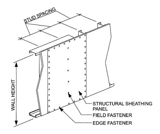
FIGURE R603.9
STRUCTURAL SHEATHING FASTENING PATTERN
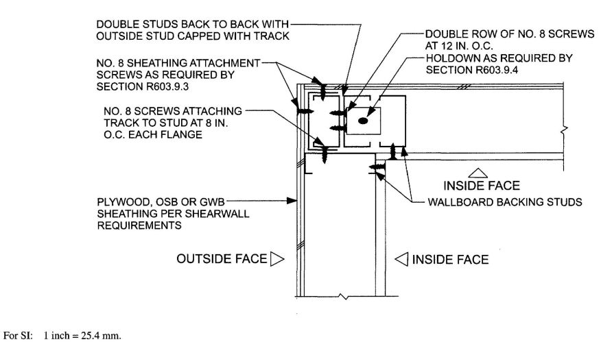
FIGURE R603.9.2
CORNER STUD HOLD DOWN DETAIL
| WALL SUPPORTING | ROOF SLOPE | BASIC WIND SPEED AND EXPOSURE (mph) |
|||||
|---|---|---|---|---|---|---|---|
| 85 B |
90 B |
100 B |
<110 B |
100 C | <110 C | ||
| 85 C | 90 C | ||||||
| For SI: 1 mile per hour = 0.447 m/s. | |||||||
| a. Linear interpolation is permitted. | |||||||
| b. For hip-roofed homes the minimum percentage of full height sheathing, based upon wind, is permitted to be multiplied by a factor of 0.95 for roof slopes not exceeding 7:12 and a factor of 0.9 for roof slopes greater than 7:12. | |||||||
| Roof and ceiling only (One story or top floor of two or three story building) |
3:12 | 8 | 9 | 9 | 12 | 16 | 20 |
| 6:12 | 12 | 13 | 15 | 20 | 26 | 35 | |
| 9:12 | 21 | 23 | 25 | 30 | 50 | 58 | |
| 12:12 | 30 | 33 | 35 | 40 | 66 | 75 | |
| One story, roof and ceiling (First floor of a two-story building or second floor of a three story building) |
3:12 | 24 | 27 | 30 | 35 | 50 | 66 |
| 6:12 | 25 | 28 | 30 | 40 | 58 | 74 | |
| 9:12 | 35 | 38 | 40 | 55 | 74 | 91 | |
| 12:12 | 40 | 45 | 50 | 65 | 100 | 115 | |
| Two story, roof and ceiling (First floor of a three story building) |
3:12 | 40 | 45 | 50 | 58 | 84 | 112 |
| 6:12 | 38 | 43 | 45 | 60 | 90 | 113 | |
| 9:12 | 49 | 53 | 55 | 80 | 98 | 124 | |
| 12:12 | 50 | 57 | 65 | 90 | 134 | 155 | |
| PLAN ASPECT RATION | LENGTH ADJUSTMENT FACTORS | |
|---|---|---|
| Short wall | Long wall | |
| 1:1 | 1.0 | 1.0 |
| 1.5:1 | 1.5 | 0.67 |
| 2:1 | 2.0 | 0.50 |
| 3:1 | 3.0 | 0.33 |
| 4:1 | 4.0 | 0.25 |
R604.1 Identification and grade. Wood structural panels shall conform to DOC PS 1 or DOC PS 2 or, when manufactured in Canada, CSA 0437 or CSA 0325. All panels shall be identified by a grade mark or certificate of inspection issued by an approvedagency.
R604.2 Allowable spans. The maximum allowable spans for wood structural panel wall sheathing shall not exceed the values set forth in Table R602.3(3).
R604.3 Installation. Wood structural panel wall sheathing shall be attached to framing in accordance with Table R602.3(1). Wood structural panels marked Exposure 1 or Exterior are considered water-repellent sheathing under the code.
R605.1 Identification and grade. Particleboard shall conform to ANSI A 208.1 and shall be so identified by a grade mark or certificate of inspection issued by an approved agency. Particleboard shall comply with the grades specified in Table R602.3(4).
R606.1 General. Masonry construction shall be designed and constructed in accordance with the provisions of this section or in accordance with the provisions of ACI 530/ASCE 5/TMS 402.
R606.1.1 Professional registration. Empirical design provisions of ACI 530/ASCE 5/TMS 402 Chapter 5 or the provisions of this section used to design mansory, project drawings, typical details and specifications shall not exempt construction documents from the requirement to be stamped by a California licensed architect or engineer. Notwithstanding other sections of law, the law establishing these provisions is found in Business and Professions Code Sections 5537.1 and 6737.1.
R606.2 Thickness of masonry. The nominal thickness of masonry walls shall conform to the requirements of Sections R606.2.1 through R606.2.4.
R606.2.1 Minimum thickness. The minimum thickness of masonry bearing walls more than one story high shall be 8 inches (203 mm). Solid masonry walls of one-story dwellings and garages shall not be less than 6 inches (152 mm) in thickness when not greater than 9 feet (2743 mm) in height, provided that when gable construction is used, an additional 6 feet (1829 mm) is permitted to the peak of the gable. Masonry walls shall be laterally supported in either the horizontal or vertical direction at intervals as required by Section R606.9.
R606.2.2 Rubble stone masonry wall. The minimum thickness of rough, random or coursed rubble stone masonry walls shall be 16 inches (406 mm).
R606.2.3 Change in thickness. Where walls of masonry of hollow units or masonry-bonded hollow walls are decreased in thickness, a course of solid masonry shall be constructed between the wall below and the thinner wall above, or special units or construction shall be used to transmit the loads from face shells or wythes above to those below.
R606.2.4 Parapet walls. Unreinforced solid masonry parapet walls shall not be less than 8 inches (203 mm) thick and their height shall not exceed four times their thickness. Unreinforced hollow unit masonry parapet walls shall be not less than 8 inches (203 mm) thick, and their height shall not exceed three times their thickness. Masonry parapet walls in areas subject to wind loads of 30 pounds per square foot (1.44 kPa) located in Seismic Design Category D0,, D1 or D2, or on townhouses in Seismic Design Category C shall be reinforced in accordance with Section R606.12.
R606.3 Corbeled masonry. Corbeled masonry shall be in accordance with Sections R606.3.1 through R606.3.3.
R606.3.1 Units.Solid masonry units or masonry units filled with mortar or grout shall be used for corbeling.
R606.3.2 Corbel projection. The maximum projection of one unit shall not exceed one-half the height of the unit or one-third the thickness at right angles to the wall. The maximum corbeled projection beyond the face of the wall shall not exceed:
R606.3.3 Corbeled masonry supporting floor or roof-framing members. When corbeled masonry is used to support floor or roof-framing members, the top course of the corbel shall be a header course or the top course bed joint shall have ties to the vertical wall.
R606.4 Support conditions. Bearing and support conditions shall be in accordance with Sections R606.4.1 and R606.4.2.
R606.4.1 Bearing on support.Each masonry wythe shall be supported by at least two-thirds of the wythe thickness.
R606.4.2 Support at foundation. Cavity wall or masonry veneer construction may be supported on an 8-inch (203 mm) foundation wall, provided the 8-inch (203 mm) wall is corbeled to the width of the wall system above with masonry constructed of solid masonry units or masonry units filled with mortar or grout. The total horizontal projection of the corbel shall not exceed 2 inches (51 mm) with individual corbels projecting not more than one-third the thickness of the unit or one-half the height of the unit. The hollow space behind the corbeled masonry shall be filled with mortar or grout.
R606.5 Allowable stresses. Allowable compressive stresses in masonry shall not exceed the values prescribed in Table R606.5. In determining the stresses in masonry, the effects of all loads and conditions of loading and the influence of all forces affecting the design and strength of the several parts shall be taken into account.
R606.5.1 Combined units. In walls or other structural members composed of different kinds or grades of units, materials or mortars, the maximum stress shall not exceed the allowable stress for the weakest of the combination of units, materials and mortars of which the member is composed. The net thickness of any facing unit that is used to resist stress shall not be less than 1.5 inches (38 mm).
R606.6 Piers. The unsupported height of masonry piers shall not exceed ten times their dimension. When structural clay tile or hollow concrete masonry units are used for isolated piers to support beams and girders, the cellular spaces shall be filled solidly with concrete or Type M or S mortar, except that unfilled hollow piers may be used if their unsupported height is not more than four times their least dimension. Where hollow masonry units are solidly filled with concrete or Type M, S or N mortor, the allowable compressive stress shall be permitted to be increased as provided in Table R606.5.
R606.6.1 Pier cap. Hollow piers shall be capped with 4 inches (102 mm) of solid masonry or concrete or shall have cavities of the top course filled with concrete or grout or other approved. methods.
R606.7 Chases. Chases and recesses in masonry walls shall not be deeper than one-third the wall thickness, and the maximum length of a horizontal chase or horizontal projection shall not exceed 4 feet (1219 mm), and shall have at least 8 inches (203 mm) of masonry in back of the chases and recesses and between adjacent chases or recesses and the jambs of openings. Chases and recesses in masonry walls shall be designed and constructed so as not to reduce the required strength or required fire resistance of the wall and in no case shall a chase or recess be permitted within the required area of a pier. Masonry directly above chases or recesses wider than 12 inches (305 mm) shall be supported on noncombustible lintels.
| CONSTRUCTION; COMPRESSIVE STRENGTH OF UNIT, GROSS AREA | ALLOWABLE COMPRESSIVE STRESSESaGROSS CROSS-SECTIONAL AREAb |
|
|---|---|---|
| Type M or S mortar |
Type N mortar |
|
| For SI: 1 pound per square inch = 6.895 kPa. | ||
| a. Linear interpolation shall be used for determining allowable stresses for masonry units having compressive strengths that are intermediate between those given in the table. | ||
| b. Gross cross-sectional area shall be calculated on the actual rather than nominal dimensions. | ||
| c. See Section R608. | ||
| d. Where floor and roof loads are carried upon one wythe, the gross cross-sectional area is that of the wythe under load; if both wythes are loaded, the gross cross-sectional area is that of the wall minus the area of the cavity between the wythes. Walls bonded with metal ties shall be considered as cavity walls unless the collar joints are filled with mortar or grout. | ||
| Solid masonry of brick and other solid units of clay or shale; |
||
| Sand-lime or concrete brick: | ||
| 8,000+ psi | 350 | 300 |
| 4,500 psi | 225 | 200 |
| 2,500 psi | 160 | 140 |
| 1,500 psi | 115 | 100 |
| Groutedc masonry, of clay or shale; | ||
| Sand-lime or concrete: | ||
| 4,500+ psi | 225 | 200 |
| 2,500 psi | 160 | 140 |
| 1,500 psi | 115 | 100 |
| Solid masonry of solid concrete masonry units: | ||
| 3,000+psi | 225 | 200 |
| 2,000 psi | 160 | 140 |
| 1,200 psi | 115 | 100 |
| Masonry of hollow load-bearing units: | ||
| 2,000+ psi | 140 | 120 |
| 1,500 psi | 115 | 100 |
| 1,000 psi | 75 | 70 |
| 700 psi | 60 | 55 |
| Hollow walls (cavity or masonry bondedd) solid units: | ||
| 2,500+psi | 160 | 140 |
| 1,500 psi | 115 | 100 |
| Hollow units | 75 | 70 |
| Stone ashlar masonry: | ||
| Granite | 720 | 640 |
| Limestone or marble | 450 | 400 |
| Sandstone or cast stone | 360 | 320 |
| Rubble stone masonry: | ||
| Coarse, rough or random | 120 | 100 |
R606.8 Stock bond. In unreinforced masonry where masonry units are laid in stack bond, longitudinal reinforcement consisting of not less than two continuous wires each with a minimum aggregate cross-sectional area of 0.017 square inch (11 mm2) shall be provided in horizontal bed joints spaced not more than 16 inches (406 mm) on center vertically.
R606.9 Lateral support. Masonry walls shall be laterally supported in either the horizontal or the vertical direction. The maximum spacing between lateral supports shall not exceed the distances in Table R606.9. Lateral support shall be provided by cross walls, pilasters, buttresses or structural frame members when the limiting distance is taken horizontally, or by floors or roofs when the limiting distance is taken vertically.
| CONSTRUCTION | MAXIMUM WALL LENGTH TO THICKNESS OR WALL HEIGHT TO THICKNESSa,b |
|---|---|
| For SI: 1 foot = 304.8 mm. | |
| a. Except for cavity walls and cantileverd walls, the thickness of a wall shall be its nominal thickness measured perpendicular to the face of the wall. For cavity walls, the thickness shall be determined as the sum of the nominal thicknesses of the individual wythes. For cantilever walls, except for parapets, the ratio of height to nominal thickness shall not exceed 6 for solid masonry, or 4 for hollow masonry. For parapets, see Section R606.2.4. | |
| b. An additional unsupported height of 6 feet is permitted for gable end walls. | |
| Bearing walls: | |
| Solid or solid grouted | 20 |
| All other | 18 |
| Nonbearing walls: | |
| Exterior | 18 |
| Interior | 36 |
R606.9.1 Horizontal lateral support. Lateral support in the horizontal direction provided by intersecting masonry wall shall be provided by one of the methods in Section R606.9.1.1 or Section R606.9.1.2.
R606.9.1.1 Bonding pattern. Fifty percent of the units at the intersection shall be laid in an overlapping masonry bonding pattern, with alternate units having a bearing of not less than 3 inches (76 mm) on the unit below.
R606.9.1.2 Metal reinforcement. Interior nonload-bearing walls shall be anchored at their intersections, at vertical intervals of not more than 16 inches (406 mm) with joint reinforcement of at least 9 Page [0.148 in (4 mm)], or ¼ inch (6 mm) galvanized mesh hardware cloth. Intersecting masonry walls, other than interior nonload bearing walls, shall be anchored at vertical intervals of not more than 8 inches (203 mm) with joint reinforcement of at least 9 gage and shall extend at least 30 inches (762 mm) in each direction at the intersection. Other metal ties, joint reinforcement or anchors, if used, shall be spaced to provide equivalent area of anchorage to that required by this section.
R606.9.2 Vertical lateral support. Vertical lateral support of masonry walls in Seismic Design Category A, B or C shall be provided in accordance with one of the methods in Section R606.9.2.1 or Section R606.9.2.2.
R606.9.2.1 Roof structures. Masonry walls shall be anchored to roof structures with metal strap anchors spaced in accordance with the manufacturer' instructions, ½ inch (13 mm) bolts spaced not more than 6 feet (1829 mm) on center, or other approved anchors. Anchors shall be embedded at least 16 inches (406 mm) into the masonry, or be hooked or welded to bond beam reinforcement placed not less than 6 inches (152 mm) from the top of the wall.
R606.9.2.2 Floor diaphragms. Masonry walls shall be anchored to floor diaphragm framing by metal strap anchors spaced in accordance with the manufacturer' instructions, ½ inch diameter (13 mm) bolts spaced at intervals not to exceed 6 feet (1829 mm) and installed as shown in Figure R606.11(1), or by other approved methods.
R606.10 Lintels. Masonry over openings shall be supported by steel lintels, reinforced concrete or masonry lintels or masonry arches, designed to support load imposed.
R606.11 Anchorage. Masonry walls shall be anchored to floor and roof systems in accordance with the details shown in Figure R606.11(1), R606.11(2) or R606.11(3). Footings may be considered as points of lateral support.
R606.12 Seismic requirements. The seismic requirements of this section shall apply to the design of masonry and the construction of masonry building elements located in Seismic Design Category D0D1 or D2. Townhouses in Seismic Design Category C shall comply with the requirements of Section R606.12.2. These requirements shall not apply to glass unit masonry conforming to Section R610 or masonry veneer conforming to Section R703.7.
R606.12.1 General. Masonry structures and masonry elements shall comply with the requirements of Section R606.12.2 through R606.12.4 based on the seismic design category established in Table R301.2(1). Masonry structures and masonry elements shall comply with the requirements of Section R606.12 and Figures R606.11(1), R606.11(2) and R606.11(3) or shall be designed in accordance with ACI 530/ASCE 5/TMS 402.
R606.12.1.1 Floor and roof diaphragm construction. Floor and roof diaphragms shall be constructed of wood structural panels attached to wood framing in accordance with Table R602.3(1) or to cold-formed steel floor framing in accordance with Table R505.3.1(2) or to cold-formed steel roof framing in accordance with Table R804.3. Additionally, sheathing panel edges perpendicular to framing members shall be backed by blocking, and sheathing shall be connected to the blocking with fasteners at the edge spacing. For Seismic Design Categories C, D0 D1 and D2. where the width-to-thickness dimension of the diaphragm exceeds 2-to-1, edge spacing of fasteners shall be 4 inches (102 mm) on center.
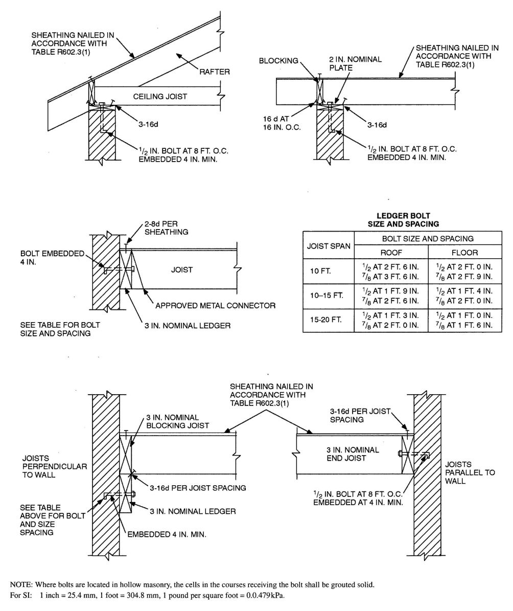
FIGURE R606.11(1)
ANCHORAGE REQUIREMENTS FOR MASONRY WALLS LOCATED IN SEISMIC DESIGN CATEGORY A, B OR C AND WHERE WIND LOADS ARE LESS THAN 30 PSF
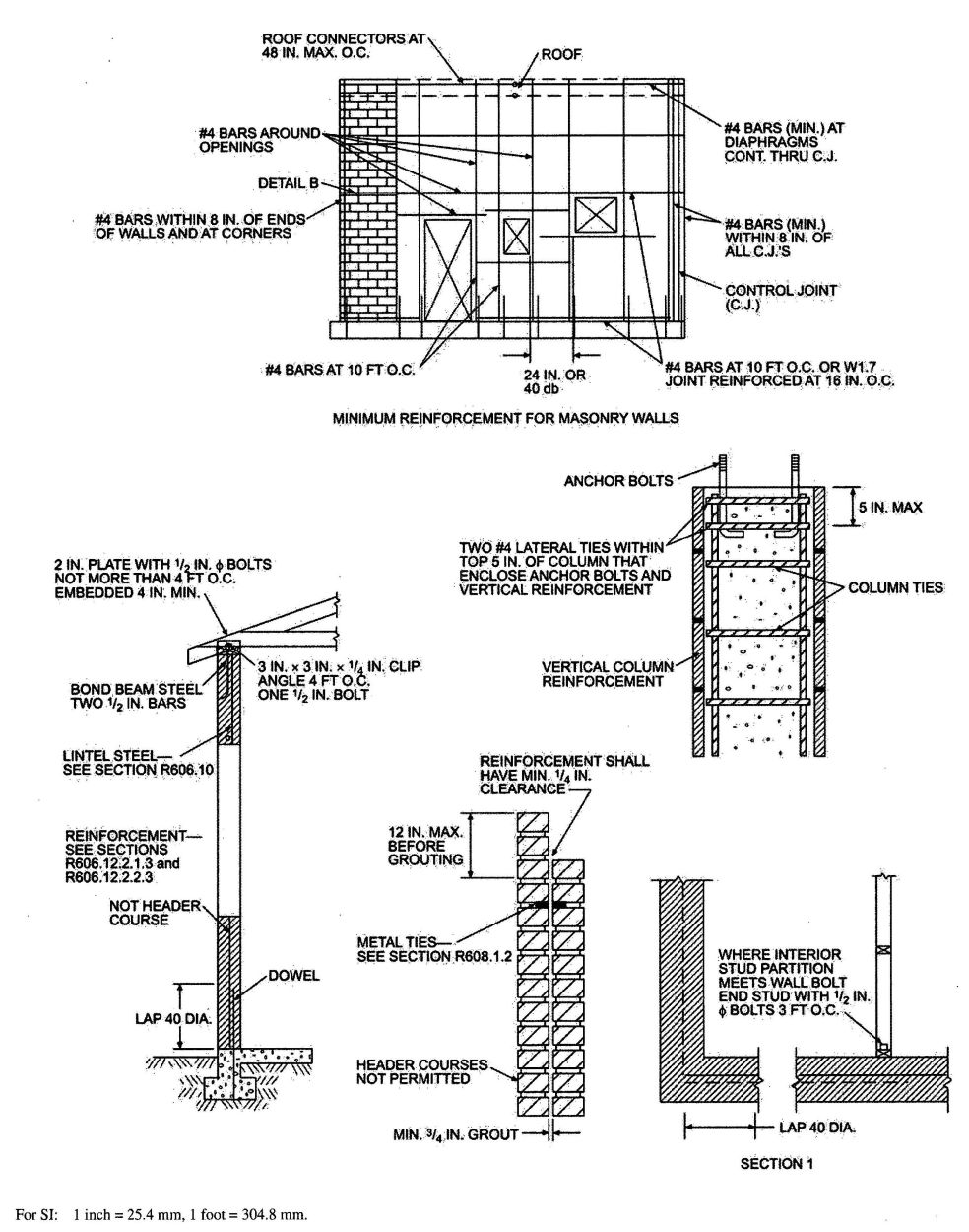
FIGURE R606.11(2)
REQUIREMENTS FOR REINFORCED GROUTED MASONRY CONSTRUCTION IN SEISMIC DESIGN CATEGORY C
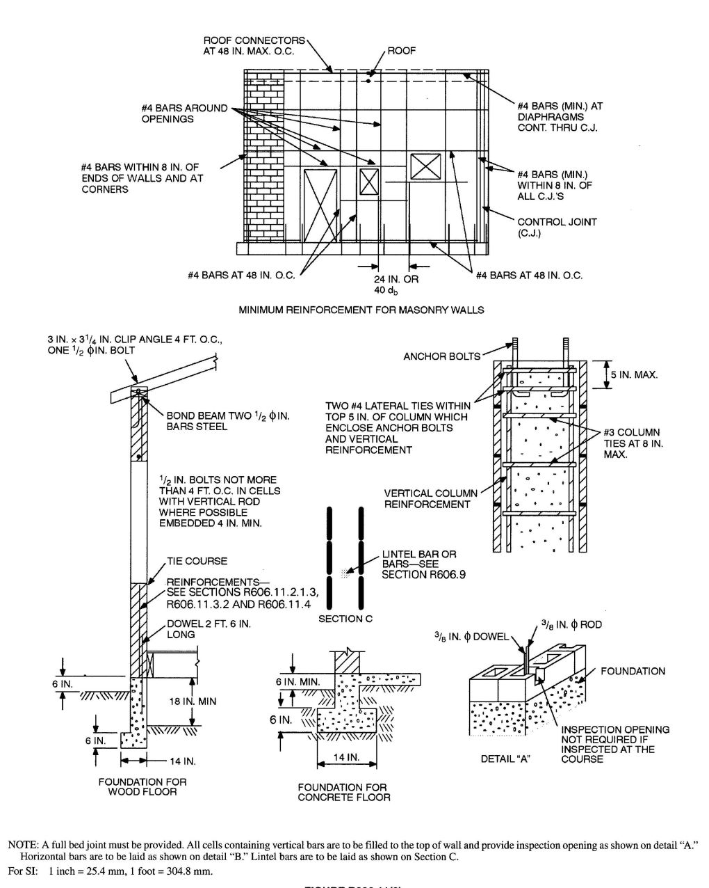
FIGURE R606.11 (3)
REQUIREMENTS FOR REINFORCED MASONRY CONSTRUCTION IN SEISMIC DESIGN CATEGORY D0, D1, OR D2
R606.12.2 Seismic Design Category C. Townhouses located in Seismic Design Category C shall comply with the requirements of this section.
R606.12.2.1 Minimum length of wall without openings. Table R606.12.2.1 shall be used to determine the minimum required solid wall length without openings at each masonry exterior wall. The provided percentage of solid wall length shall include only those wall segments that are 3 feet (914 mm) or longer. The maximum clear distance between wall segments included in determining the solid wall length shall not exceed 18 feet (5486 mm). Shear wall segments required to meet the minimum wall length shall be in accordance with Section R606.12.2.2.3.
R606.12.2.2 Design of elements not part of the lateral force-resisting system.
R606.12.2.2.1 Load-bearing frames or columns. Elements not part of the lateral-force-resisting system shall be analyzed to determine their effect on the response of the system. The frames or columns shall be adequate for vertical load carrying capacity and induced moment caused by the design story drift.
R606.12.2.2.2 Masonry partition walls. Masonry partition walls, masonry screen walls and other masonry elements that are not designed to resist vertical or lateral loads, other than those induced by their own weight, shall be isolated from the structure so that vertical and lateral forces are not imparted to these elements. Isolation joints and connectors between these elements and the structure shall be designed to accommodate the design story drift.
R606.12.2.2.3 Reinforcement requirements for masonry elements. Masonry elements listed in Section R606.12.2.2.2 shall be reinforced in either the horizontal or vertical direction as shown in Figure R606.11(2) and in accordance with the following:
R606.12.2.3 Design of elements part of the lateral-force-resisting system.
R606.12.2.3.1 Connections to masonry shear walls. Connectors shall be provided to transfer forces between masonry walls and horizontal elements in accordance with the requirements of Section 2.1.8 of ACI 530/ASCE 5/TMS 402. Connectors shall be designed to transfer horizontal design forces acting either perpendicular or parallel to the wall, but not less than 200 pounds per linear foot (2919 N/m) of wall. The maximum spacing between connectors shall be 4 feet (1219 mm). Such anchorage mechanisms shall not induce tension stresses perpendicular to grain in ledgers or nailers.
R606.12.2.3.2 Connections to masonry columns. Connectors shall be provided to transfer forces between masonry columns and horizontal elements in accordance with the requirements of Section 2.1.8 of ACI 530/ASCE 5/TMS 402. Where anchor bolts are used to connect horizontal elements to the tops of columns, the bolts shall be placed within lateral ties. Lateral ties shall enclose both the vertical bars in the column and the anchor bolts. There shall be a minimum of two No. 4 lateral ties provided in the top 5 inches (127 mm) of the column.
R606.12.2.3.3 Minimum reinforcement requirements for masonry shear walls. Vertical reinforcement of at least one No. 4 bar shall be provided at corners, within 16 inches (406 mm) of each side of
| SESIMIC DESIGN CATEGORY | MINIMUM SOLID WALL LENGTH (percent)a | ||
|---|---|---|---|
| One Story or Top Story or Two Story | Wall Supporting Light-framed Second Story and Roof | Wall Supporting Masonry Second Story and Roof | |
| NP = Not permitted, except with design in accordance with the California Building Code. | |||
| a. For all walls, the minimum required length of solid walls shall be based on the table percent multiplied by the dimension, parallel to the wall direction under consideration, of a rectangle inscribing the overall building plan. | |||
| Townhouses in C | 20 | 25 | 35 |
| D0 or D1 | 25 | NP | NP |
| D2 | 30 | NP | NP |
openings, within 8 inches (203 mm) of each side of movement joints, within 8 inches (203 mm) of the ends of walls, and at a maximum spacing of 10 feet (3048 mm).
Horizontal joint reinforcement shall consist of at least two wires of W1.7 spaced not more than 16 inches (406 mm); or bond beam reinforcement of at least one No. 4 bar spaced not more than 10 feet (3048 mm) shall be provided. Horizontal reinforcement shall also be provided at the bottom and top of wall openings and shall extend not less than 24 inches (610 mm) not less than 40 bar diameters past the opening; continuously at structurally connected roof and floor levels; and within 16 inches (406 mm) of the top of walls.
R606.12.3 Seismic Design Category D0 or D1. Structures in Seismic Design Category D0 or D1 shall comply with the requirements of Seismic Design Category C and the additional requirements of this section.
R606.12.3.1 Design requirements. Masonry elements other than those covered by Section R606.12.2.2.2 shall be designed in accordance with the requirements of Chapter 1 and Sections 2.1 and 2.3 of ACI 530/ASCE 5/TMS 402 and shall meet the minimum reinforcement requirements contained in Sections R606.12.3.2 and R606.12.3.2.1.
Exception: Masonry walls limited to one story in height and 9 feet (2743 mm) between lateral supports need not be designed provided they comply with the minimum reinforcement requirements of Sections R606.12.3.2 and R606.12.3.2.1.
R606.12.3.2 Minimum reinforcement requirements for masonry walls. Masonry walls other than those covered by Section R606.12.2.2.3 shall be reinforced in both the vertical and horizontal direction. The sum of the cross-sectional area of horizontal and vertical reinforcement shall be at least 0.002 times the gross cross-sectional area of the wall, and the minimum cross-sectional area in each direction shall be not less than 0.0007 times the gross cross-sectional area of the wall. Reinforcement shall be uniformly distributed. Table R606.12.3.2 shows the minimum reinforcing bar sizes required for varying thicknesses of masonry walls. The maximum spacing of reinforcement shall be 48 inches (1219 mm) provided that the walls are solid grouted and constructed of hollow open-end units, hollow units laid with full head joints or two wythes of solid units. The maximum spacing of reinforcement shall be 24 inches (610 mm) for all other masonry.
R606.12.3.2.1 Shear wall reinforcement requirements. The maximum spacing of vertical and horizontal reinforcement shall be the smaller of one-third the length of the shear wall, one-third the height of the shear wall, or 48 inches (1219 mm). The minimum cross-sectional area of vertical reinforcement shall be one-third of the required shear reinforcement. Shear reinforcement shall be anchored around vertical reinforcing bars with a standard hook.
R606.12.3.3 Minimum reinforcement for masonry columns. Lateral ties in masonry columns shall be spaced not more than 8 inches (203 mm) on center and shall be at least 3/8 inch (9.5 mm) diameter. Lateral ties shall be embedded in grout.
R606.12.3.4 Material restrictions. Type N mortar or masonry cement shall not be used as part of the lateral-force-resisting system.
R606.12.3.5 Lateral tie anchorage. Standard hooks for lateral tie anchorage shall be either a 135-degree (2.4 rad) standard hook or a 180-degree (3.2 rad) standard hook.
R606.12.4 Seismic Design Category D2. All structures in Seismic Design Category D2 shall comply with the requirements of Seismic Design Category D1 and to the additional requirements of this section.
R606.12.4.1 Design of elements not part of the lateral-force-resisting system. Stack bond masonry that is not part of the lateral-force-resisting system shall have a horizontal cross-sectional area of reinforcement of at least 0.0015 times the gross cross-sectional area of masonry. Table R606.12.4.1 shows minimum reinforcing bar sizes for masonry walls. The maximum spacing of horizontal reinforcement shall be 24 inches (610 mm). These elements shall be solidly grouted and shall be constructed of hollow open-end units or two wythes of solid units.
| NOMINAL WALL THICKNESS (inches) | MINIMUM SUM OF THE VERTICAL AND HORIZONTAL REINFORCEMENT AREASa (square inches per foot) | MINIMUM REINFORCEMENT AS DISTRIBUTED IN BOTH HORIZONTAL AND VERTICAL DIRECTIONSb (square inches per foot) | MINIMUM BAR SIZE FOR REINFORCEMENT SPACED AT 48 INCHES |
|---|---|---|---|
| For SI: 1 inch = 25.4 mm, 1 foot = 304.8 mm, 1 square inch per foot = 2064 mm2/m. | |||
| a. Based on the minimum reinforcing ratio of 0.002 times the gross cross-sectional area of the wall. | |||
| b. Based on the minimum reinforcing ratio each direction of 0.0007 times the gross cross-sectional area of the wall. | |||
| 6 | 0.135 | 0.047 | #4 |
| 8 | 0.183 | 0.064 | #5 |
| 10 | 0.231 | 0.081 | #6 |
| 12 | 0.279 | 0.098 | #6 |
| NOMINAL WALL THICKNESS (inches) | MINIMUM BAR SIZE SPACED AT 24 INCHES |
|---|---|
| For SI: 1 inch = 25.4 mm. | |
| 6 | #4 |
| 8 | #5 |
| 10 | #5 |
| 12 | #6 |
R606.12.4.2 Design of elements part of the lateral-force-resisting system. Stack bond masonry that is part of the lateral-force-resisting system shall have a horizontal cross-sectional area of reinforcement of at least 0.0025 times the gross cross-sectional area of masonry. Table R606.12.4.2 shows minimum reinforcing bar sizes for masonry walls. The maximum spacing of horizontal reinforcement shall be 16 inches (406 mm). These elements shall be solidly grouted and shall be constructed of hollow open-end units or two wythes of solid units.
| NOMINAL WALL THICKNESS (inches) | MINIMUM BAR SIZE SPACED AT 16 INCHES |
|---|---|
| For SI: 1 inch=25.4 mm. | |
| 6 | #4 |
| 8 | #5 |
| 10 | #5 |
| 12 | #6 |
R606.13 Protection for reinforcement. Bars shall be completely embedded in mortar or grout. Joint reinforcement embedded in horizontal mortar joints shall not have less than 5/8-inch (15.9 mm) mortar coverage from the exposed face. All other reinforcement shall have a minimum coverage of one bar diameter over all bars, but not less than ¾ inch (19 mm), except where exposed to weather or soil, in which case the minimum coverage shall be 2 inches (51 mm).
R606.14 Beam supports. Beams, girders or other concentrated loads supported by a wall or column shall have a bearing of at least 3 inches (76 mm) in length measured parallel to the beam upon solid masonry not less than 4 inches (102 mm) in thickness, or upon a metal bearing plate of adequate design and dimensions to distribute the load safely, or upon a continuous reinforced masonry member projecting not less than 4 inches (102 mm) from the face of the wall.
R606.14.1 Joist bearing. Joists shall have a bearing of not less than 1½ inches (38 mm), except as provided in Section R606.14, and shall be supported in accordance with Figure R606.11(1).
R606.15 Metal accessories. Joint reinforcement, anchors, ties and wire fabric shall conform to the following: ASTM A 82 for wire anchors and ties; ASTM A 36 for plate, headed and bent-bar anchors; ASTM A 510 for corrugated sheet metal anchors and ties; ASTM A 951 for joint reinforcement; ASTM B 227 for copper-clad steel wire ties; or ASTM A 167 for stainless steel hardware.
R606.15.1 Corrosion protection. Minimum corrosion protection of joint reinforcement, anchor ties and wire fabric for use in masonry wall construction shall conform to Table R606.15.1.
| MASONRY METAL ACCESSORY | STANDARD |
|---|---|
| Joint reinforcement, interior walls | ASTM A 641, Class 1 |
| Write ties or anchors in exterior walls completely embedded in mortar or grout | ASTM A 641, Class 3 |
| Write ties or anchors in exterior walls not completely embedded in mortar or grout | ASTM A 153, Class B-2 |
| Joint reinforcement in exterior walls or interior walls exposed to moist environment | ASTM A 153, Class B-2 |
| Sheet metal ties or anchors exposed to weather | ASTM A 153, Class B-2 |
| Sheet metal ties or anchors completely embedded in mortar or grout | ASTM A 653, Coating Designation G60 |
| Stainless steel hardware for any exposure | ASTM A 167, Type 304 |
R607.1 Mortar. Mortar for use in masonry construction shall comply with ASTM C 270. The type of mortar shall be in accordance with Sections R607.1.1, R607.1.2 and R607.1.3 and shall meet the proportion specifications of Table R607.1 or the property specifications of ASTM C 270.
R607.1.1 Foundation walls. Masonry foundation walls constructed as set forth in Tables R404.1.1(1) through R404.1.1(4) and mortar shall be Type M or S.
R607.1.2 Masonry in Seismic Design Categories A, B and C. Mortar for masonry serving as the lateral-force-resisting system in Seismic Design Categories A, B and C shall be Type M, S or N mortar.
R607.1.3 Masonry in Seismic Design Categories D0, D1 and D2. Mortar for masonry serving as the lateral-force-resisting system in Seismic Design Categories D0, D1 and D2 shall be Type M or S portland cement-lime or mortar cement mortar.
R607.2 Placing mortar and masonry units.
R607.2.1 Bed and head joints. Unless otherwise required or indicated on the project drawings, head and bed joints shall be 3/8 inch (10 mm) thick, except that the thickness of the bed joint of the starting course placed over foundations shall not be less than ¼inch (7 mm) and not more than ¾ inch (19 mm).
| PROPORTIONS BY VOLUME (cementitious materials) | ||||||||||
|---|---|---|---|---|---|---|---|---|---|---|
| MORTAR | TYPE | Portland cement or blended cement | Mortar cement | Masonry cement | Hydrated limec or lime putty | Aggregate ratio (measured in damp, loose conditions) | ||||
| M | S | N | M | S | N | |||||
| For SI: 1 cubic foot = 0.0283 m3, 1 pound = 0.454 kg. | ||||||||||
| a. For the purpose of these specifications, the weight of 1 cubic foot of the respective materials shall be considered to be as follows: | ||||||||||
| Portland Cement | 94 pounds | Masonry Cement | Weight printed on bag | |||||||
| Mortar Cement | Weight printed on bag | Hydrated Lime | 40 pounds | |||||||
| Lime Putty (Quicklime) | 80 pounds | Sand, damp and loose | 80 pounds of dry sand | |||||||
| b. Two air-entraining materials shall not be combined in mortar. | ||||||||||
| Cement-lime | M | 1 | — | — | — | — | — | — | ¼ | Not less than 2¼ and not more than 3 times the sum of separate volumes of lime, if used, and cement |
| S | 1 | — | — | — | — | — | — | over ¼ to ½ | ||
| N | 1 | — | — | — | — | — | — | over ½ to 1¼ | ||
| O | 1 | — | — | — | — | — | — | over 1¼ to 2½ | ||
| Mortar cement | M | 1 | — | — | 1 | — | — | — | — | |
| M | — | 1 | — | — | — | — | — | |||
| S | ½ | — | — | 1 | — | — | — | |||
| S | — | — | 1 | — | — | — | — | |||
| N | — | — | — | 1 | — | — | — | |||
| O | — | — | — | 1 | — | — | — | |||
| Masonry cement | M | 1 | — | — | 1 | — | ||||
| M | — | 1 | — | — | ||||||
| S | ½ | — | — | 1 | ||||||
| S | — | — | 1 | — | ||||||
| N | — | — | — | 1 | ||||||
| O | — | — | — | 1 | ||||||
R607.2.1.1 Mortar joint thickness tolerance. Mortar joint thickness for load-bearing masonry shall be within the following tolerances from the specified dimensions:
R607.2.2 Masonry unit placement. The mortar shall be sufficiently plastic and units shall be placed with sufficient pressure to extrude mortar from the joint and produce a tight joint. Deep furrowing of bed joints that produces voids shall not be permitted. Any units disturbed to the extent that initial bond is broken after initial placement shall be removed and relaid in fresh mortar. Surfaces to be in contact with mortar shall be clean and free of deleterious materials.
R607.2.2.1 Solid masonry. Solid masonry units shall be laid with full head and bed joints and all interior vertical joints that are designed to receive mortar shall be filled.
R607.2.2.2 Hollow masonry. For hollow masonry units, head and bed joints shall be filled solidly with mortar for a distance in from the face of the unit not less than the thickness of the face shell.
R607.3 Installation of wall ties. The installation of wall ties shall be as follows:
R608.1 General. The facing and backing of multiple wythe masonry walls shall be bonded in accordance with Section R608.1.1, R608.1.2 or R608.1.3. In cavity walls, neither the facing nor the backing shall be less than 3 inches (76 mm) nominal in thickness and the cavity shall not be more than 4 inches (102 mm) nominal in width. The backing shall be at least as thick as the facing.
Exception: Cavities shall be permitted to exceed the 4-inch (102 mm) nominal dimension provided the size and the spacing have been established by calculation.
R608.1.1 Bonding with masonry headers. Bonding with solid or hollow masonry headers shall comply with Sections R608.1.1.1 and R608.1.1.2.
R608.1.1.1 Solid units. Where the facing and backing (adjacent wythes) of solid masonry construction are bonded by means of masonry headers, no less than 4 percent of the wall surface of each face shall be composed of headers extending not less than 3 inches (76 mm) into the backing. The distance between adjacent full-length headers shall not exceed 24 inches (610 mm) either vertically or horizontally. In walls in which a single header does not extend through the wall, headers from the opposite sides shall overlap at least 3 inches (76 mm), or headers from opposite sides shall be covered with another
324header course overlapping the header below at least 3 inches (76 mm).
R608.1.1.2 Hollow units. Where two or more hollow units are used to make up the thickness of a wall, the stretcher courses shall be bonded at vertical intervals not exceeding 34 inches (864 mm) by lapping at least 3 inches (76 mm) over the unit below, or by lapping at vertical intervals not exceeding 17 inches (432 mm) with units that are at least 50 percent thicker than the units below.
R608.1.2 Bonding with wall ties or joint reinforcement. Bonding with wall ties or joint reinforcement shall comply with Sections R608.1.2.1 through R608.1.2.3.
R608.1.2.1 Bonding with wall ties. Bonding with wall ties, except as required by Section R610, where the facing and backing (adjacent wythes) of masonry walls are bonded with 3/16-inch-diameter (5 mm) wall ties embedded in the horizontal mortar joints, there shall be at least one metal tie for each 4.5 square feet (0.418 m2) of wall area. Ties in alternate courses shall be staggered. The maximum vertical distance between ties shall not exceed 24 inches (610 mm), and the maximum horizontal distance shall not exceed 36 inches (914 mm). Rods or ties bent to rectangular shape shall be used with hollow masonry units laid with the cells vertical. In other walls, the ends of ties shall be bent to 90-degree (0.79 rad) angles to provide hooks no less than 2 inches (51 mm) long. Additional bonding ties shall be provided at all openings, spaced not more than 3 feet (914 mm) apart around the perimeter and within 12 inches (305 mm) of the opening.
R608.1.2.2 Bonding with adjustable wall ties. Where the facing and backing (adjacent wythes) of masonry are bonded with adjustable wall ties, there shall be at least one tie for each 2.67 square feet (0.248 m2) of wall area. Neither the vertical nor the horizontal spacing of the adjustable wall ties shall exceed 24 inches (610 mm). The maximum vertical offset of bed joints from one wythe to the other shall be 1.25 inches (32 mm). The maximum clearance between connecting parts of the ties shall be 1/16 inch (2 mm). When pintle legs are used, ties shall have at least two 3/16-inch-diameter (5 mm) legs.
R608.1.2.3 Bonding with prefabricated joint reinforcement. Where the facing and backing (adjacent wythes) of masonry are bonded with prefabricated joint reinforcement, there shall be at least one cross wire serving as a tie for each 2.67 square feet (0.248 m2) of wall area. The vertical spacing of the joint reinforcement shall not exceed 16 inches (406 mm). Cross wires on prefabricated joint reinforcement shall not be smaller than No. 9 gage. The longitudinal wires shall be embedded in the mortar.
R608.1.3 Bonding with natural or cast stone. Bonding with natural and cast stone shall conform to Sections R608.1.3.1 and R608.1.3.2.
R608.1.3.1 Ashlar masonry. In ashlar masonry, bonder units, uniformly distributed, shall be provided to the extent of not less than 10 percent of the wall area. Such bonder units shall extend not less than 4 inches (102 mm) into the backing wall.
R608.1.3.2 Rubble stone masonry. Rubble stone masonry 24 inches (610 mm) or less in thickness shall have bonder units with a maximum spacing of 3 feet (914 mm) vertically and 3 feet (914 mm) horizontally, and if the masonry is of greater thickness than 24 inches (610 mm), shall have one bonder unit for each 6 square feet (0.557 m2) of wall surface on both sides.
R608.2 Masonry bonding pattern. Masonry laid in running and stack bond shall conform to Sections R608.2.1 and R608.2.2.
R608.2.1 Masonry laid in running bond. In each wythe of masonry laid in running bond, head joints in successive courses shall be offset by not less than one-fourth the unit length, or the masonry walls shall be reinforced longitudinally as required in Section R608.2.2.
R608.2.2 Masonry laid in stack bond. Where unit masonry is laid with less head joint offset than in Section R607.2.1, the minimum area of horizontal reinforcement placed in mortar bed joints or in bond beams spaced not more than 48 inches (1219 mm) apart, shall be 0.0007 times the vertical cross-sectional area of the wall.
R609.1 General. Grouted multiple-wythe masonry is a form of construction in which the space between the wythes is solidly filled with grout. It is not necessary for the cores of masonry units to be filled with grout. Grouted hollow unit masonry is a form of construction in which certain cells of hollow units are continuously filled with grout.
R609.1.1 Grout. Grout shall consist of cementitious material and aggregate in accordance with ASTM C 476 and the proportion specifications of Table R609.1.1 Type M or Type S mortar to which sufficient water has been added to produce pouring consistency can be used as grout.
R609.1.2 Grouting requirements. Maximum pour heights and the minimum dimensions of spaces provided for grout placement shall conform to Table R609.1.2. If the work is stopped for one hour or longer, the horizontal construction joints shall be formed by stopping all tiers at the same elevation and with the grout 1 inch (25 mm) below the top.
R609.1.3 Grout space (cleaning). Provision shall be made for cleaning grout space. Mortar projections that project more than 0.5 inch (13 mm) into grout space and any other foreign matter shall be removed from grout space prior to inspection and grouting.
R609.1.4 Grout placement. Grout shall be a plastic mix suitable for pumping without segregation of the constitutents and shall be mixed throughly. Grout shall be placed by pumping or by an approved alternate method and shall be placed before any initial set occurs and in no case more than 1½ hours after water has been added. Grouting shall be done in a continuous pour, in lifts not exceeding 5 feet (1524 mm). It shall be consolidated by puddling or mechanical
325vibrating during placing and reconsolidated after excess moisture has been absorbed but before plasticity is lost.
R609.1.4.1 Grount pumped through aluminum pipes. Grout shall not be pumped through aluminum pipes.
R609.1.5 Cleanouts. Where required by the building official, cleanouts shall be provided as specified in this section. The cleanouts shall be sealed before grouting and after inspection.
R609.1.5.1 Grouted multiple-wythe masonry. Cleanouts shall be provided at the bottom course of the exterior wythe at each pour of grout where such pour exceeds 5 feet (1524 mm) in height.
R609.1.5.2 Grouted hollow unit masonry. Cleanouts shall be provided at the bottom course of each cell to be grouted at each pour of grout, where such pour exceeds 4 feet (1219 mm) in height.
R609.2 Grouted multiple-wythe masonry. Grouted multiple-wythe masonry shall conform to all the requirements specified in Section R609.1 and the requirements of this section.
R609.2.1 Bonding of backup wythe. Where all interior vertical spaces are filled with grout in multiple-wythe construction, masonry headers shall not be permitted. Metal wall ties shall be used in accordance with Section R608.1.2 to prevent spreading of the wythes and to maintain the vertical alignment of the wall. Wall ties shall be installed in accordance with Section R608.1.2 when the backup wythe in multiple-wythe construction is fully grouted.
R609.2.2 Grout spaces. Fine grout shall be used when interior vertical space to receive grout does not exceed 2 inches (51 mm) in thickness. Interior vertical spaces exceeding 2 inches (51 mm) in thickness shall use coarse or fine grout.
R609.2.3 Grout barriers. Vertical grout barriers or dams shall be built of solid masonry across the grout space the entire height of the wall to control the flow of the grout horizontally. Grout barriers shall not be more than 25 feet (7620 mm) apart. The grouting of any section of a wall between control barriers shall be completed in one day with no interruptions greater than one hour.
R609.3 Reinforced grouted multiple-wythe masonry. Reinforced grouted multiple-wythe masonry shall conform to all the requirements specified in Sections R609.1 and R609.2 and the requirements of this section.
R609.3.1 Construction. The thickness of grout or mortar between masonry units and reinforcement shall not be less than ¼ inch (7 mm), except that ¼ inch (7 mm) bars may be laid in horizontal mortar joints at least ½ inch (13 mm) thick, and steel wire reinforcement may be laid in horizontal mortar joints at least twice the thickness of the wire diameter.
| TYPE | PORTLAND CEMENT OR BLENDED CEMENT SLAG CEMENT | HYDRATED LIME OR LIME PUTTY | AGGREGATE MEASURED IN A DAMP, LOOSE CONDITION | |
|---|---|---|---|---|
| Fine | Coarse | |||
| For SI: 1 inch = 25.4 mm, 1 foot = 304.8 mm. | ||||
| a. For grouting between masonry wythes. | ||||
| b. Grout space dimension is the clear dimension between any masonry protrusion and shall be increased by the horizontal projection of the diameters of the horizontal bars within the cross section of the grout space. | ||||
| c. Area of vertical reinforcement shall not exceed 6 percent of the area of the grout space. | ||||
| Fine | 1 | 0 to 1/10 | 2¼ to 3 times the sum of the volume of the cementitious materials | — |
| Coarse | 1 | 0 to 1/10 | 2¼ to 3 times the sum of the volume of the cementitious materials | 1 to 2 times the sum of the volumes of the cementitious materials |
| GROUT TYPE | GROUT POUR MAXIMUM HEIGHT (feet) | MINIMUM WIDTH OF GROUT SPACESa,b (inches) | MINIMUM GROUTb,c SPACE DIMENSIONS FOR GROUTING CELLS OF HOLLOW UNITS (inches x inches) |
|---|---|---|---|
| Fine | 1 | 0.75 | 1.5 X 2 |
| 5 | 2 | 2 X 3 | |
| 12 | 2.5 | 2.5 X 3 | |
| 24 | 3 | 3 X 3 | |
| Coarse | 1 | 1.5 | 1.5 X 3 |
| 5 | 2 | 2.5 X 3 | |
| 12 | 2.5 | 3 X 3 | |
| 24 | 3 | 3 X 4 |
R609.4 Reinforced hollow unit masonry. Reinforced hollow unit masonry shall conform to all the requirements of Section R609.1 and the requirements of this section.
R609.4.1 Construction. Requirements for construction shall be as follows:
R610.1 General. Panels of glass unit masonry located in load-bearing and nonload-bearing exterior and interior walls shall be constructed in accordance with this section.
R610.2 Materials. Hollow glass units shall be partially evacuated and have a minimum average glass face thickness of 3/16 inch (5 mm). The surface of units in contact with mortar shall be treated with a polyvinyl butyral coating or latex-based paint. The use of reclaimed units is prohibited.
R610.3 Units. Hollow or solid glass block units shall be standard or thin units.
R610.3.1 Standard units. The specified thickness of standard units shall be at least 3⁄78 inches (98 mm).
R610.3.2 Thin units. The specified thickness of thin units shall be at least 3⁄18 inches (79 mm) for hollow units and at least 3 inches (76 mm) for solid units.
R610.4 Isolated panels. Isolated panels of glass unit masonry shall conform to the requirements of this section.
R610.4.1 Exterior standard-unit panels. The maximum area of each individual standard-unit panel shall be 144 square feet (13.4 m2) when the design wind pressure is 20 psf (958 Pa). The maximum area of such panels subjected to design wind pressures other than 20 psf (958 Pa) shall be in accordance with Figure R610.4.1. The maximum panel dimension between structural supports shall be 25 feet (7620 mm) in width or 20 feet (6096 mm) in height.
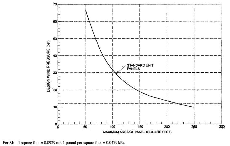
FIGURE R610.4.1
GLASS UNIT MASONRY DESIGN WIND LOAD RESISTANCE
R610.4.2 Exterior thin-unit panels. The maximum area of each individual thin-unit panel shall be 85 square feet (7.9 m2). The maximum dimension between structural supports shall be 15 feet (4572 mm) in width or 10 feet (3048 mm) in height. Thin units shall not be used in applications where the design wind pressure as stated in Table R301.2(1) exceeds 20 psf (958 Pa).
R610.4.3 Interior panels. The maximum area of each individual standard-unit panel shall be 250 square feet (23.2 m2). The maximum area of each thin-unit panel shall be 150 square feet (13.9 m2). The maximum dimension between structural supports shall be 25 feet (7620 mm) in width or 20 feet (6096 mm) in height.
R610.4.4 Curved panels. The width of curved panels shall conform to the requirements of Sections R610.4.1, R610.4.2 and R610.4.3, except additional structural supports shall be provided at locations where a curved section joins a straight section, and at inflection points in multicurved walls.
R610.5 Panel support. Glass unit masonry panels shall conform to the support requirements of this section.
R610.5.1 Deflection. The maximum total deflection of structural members that support glass unit masonry shall not exceed 1/600.
R610.5.2 Lateral support. Glass unit masonry panels shall be laterally supported along the top and sides of the panel. Lateral supports for glass unit masonry panels shall be designed to resist a minimum of 200 pounds per lineal feet (2918 N/m) of panel, or the actual applied loads, whichever is greater. Except for single unit panels, lateral support shall be provided by panel anchors along the top and sides spaced a maximum of 16 inches (406 mm) on center or by channel-type restraints. Single unit panels shall be supported by channel-type restraints.
Exceptions:
- Lateral support is not required at the top of panels that are one unit wide.
- Lateral support is not required at the sides of panels that are one unit high.
R610.5.2.1 Panel anchor restraints. Panel anchors shall be spaced a maximum of 16 inches (406 mm) on center in both jambs and across the head. Panel anchors shall be embedded a minimum of 12 inches (305 mm) and shall be provided with two fasteners so as to resist the loads specified in Section R610.5.2.
R610.5.2.2 Channel-type restraints. Glass unit masonry panels shall be recessed at least 1 inch (25 mm) within channels and chases. Channel-type restraints shall be oversized to accommodate expansion material in the opening, packing and sealant between the framing restraints, and the glass unit masonry perimeter units.
R610.6 Sills. Before bedding of glass units, the sill area shall be covered with a water base asphaltic emulsion coating. The coating shall be a minimum of 1/8 inch (3 mm) thick.
R610.7 Expansion joints. Glass unit masonry panels shall be provided with expansion joints along the top and sides at all structural supports. Expansion joints shall be a minimum of 3/8 inch (10 mm) in thickness and shall have sufficient thickness to accommodate displacements of the supporting structure. Expansion joints shall be entirely free of mortar and other debris and shall be filled with resilient material.
R610.8 Mortar. Glass unit masonry shall be laid with Type S or N mortar. Mortar shall not be retempered after initial set. Mortar unused within 1½ hours after initial mixing shall be discarded.
R610.9 Reinforcement. Glass unit masonry panels shall have horizontal joint reinforcement spaced a maximum of 16 inches (406 mm) on center located in the mortar bed joint. Horizontal joint reinforcement shall extend the entire length of the panel but shall not extend across expansion joints. Longitudinal wires shall be lapped a minimum of 6 inches (152 mm) at splices. Joint reinforcement shall be placed in the bed joint immediately below and above openings in the panel. The reinforcement shall have not less than two parallel longitudinal wires of size W1.7 or greater, and have welded cross wires of size W1.7 or greater.
R610.10 Placement. Glass units shall be placed so head and bed joints are filled solidly. Mortar shall not be furrowed. Head and bed joints of glass unit masonry shall be ¼ inch (6.4 mm) thick, except that vertical joint thickness of radial panels shall not be less than 1/8 inch (3 mm) or greater than 5/8 inch (16 mm). The bed joint thickness tolerance shall be minus 1/16 inch (1.6 mm) and plus 1/8 inch (3 mm). The head joint thickness tolerance shall be plus or minus 1/8 inch (3 mm).
R611.1 General. Exterior concrete walls shall be designed and constructed in accordance with the provisions of this section or in accordance with the provisions of PCA 100 or ACI 318. PCA 100, ACI 318 or the provisions of this section used to design concrete walls, project drawings, typical details and specifications shall not exempt construction documents from the requirement to be stamped by a California licensed architect or engineer. Notwithstanding other sections of law, the law establishing these provisions is found in Business and Professions Code Sections 5537.1 and 6737.1.
R611.1.1 Interior construction. These provisions are based on the assumption that interior walls and partitions, both load-bearing and nonload-bearing, floors and roof/ceiling assemblies are constructed of light-framed construction complying with the limitations of this code and the additional limitations of Section R611.2. Design and construction of light-framed assemblies shall be in accordance with the applicable provisions of this code. Where second-story exterior walls are of light-framed construction, they shall be designed and constructed as required by this code.
Aspects of concrete construction not specifically addressed by this code, including interior concrete walls, shall comply with ACI 318.
R611.1.2 Other concrete walls. Exterior concrete walls constructed in accordance with this code shall comply with the shapes and minimum concrete cross-sectional dimen-
328sions of Table R611.3. Other types of forming systems resulting in concrete walls not in compliance with this section shall be designed in accordance with ACI 318.
R611.2 Applicability limits. The provisions of this section shall apply to the construction of exterior concrete walls for buildings not greater than 60 feet (18 288 mm) in plan dimensions, floors with clear spans not greater than 32 feet (9754 mm) and roofs with clear spans not greater than 40 feet (12 192 mm). Buildings shall not exceed 35 feet (10 668 mm) in mean roof height or two stories in height above-grade. Floor/ceiling dead loads shall not exceed 10 pounds per square foot (479 Pa), roof/ceiling dead loads shall not exceed 15 pounds per square foot (718 Pa) and attic live loads shall not exceed 20 pounds per square foot (958 Pa). Roof overhangs shall not exceed 2 feet (610 mm) of horizontal projection beyond the exterior wall and the dead load of the overhangs shall not exceed 8 pounds per square foot (383 Pa).
Walls constructed in accordance with the provisions of this section shall be limited to buildings subjected to a maximum design wind speed of 130 miles per hour (58 m/s) Exposure B, 110 miles per hour (49 m/s) Exposure C and 100 miles per hour (45 m/s) Exposure D. Walls constructed in accordance with the provisions of this section shall be limited to detached one-and two-family dwellings and townhouses assigned to Seismic Design Category A or B, and detached one- and two-family dwellings assigned to Seismic Design Category C.
Buildings that are not within the scope of this section shall be designed in accordance with PCA 100 or ACI 318.
R611.3 Concrete wall systems. Concrete walls constructed in accordance with these provisions shall comply with the shapes and minimum concrete cross-sectional dimensions of Table R611.3.
R611.3.1 Flat wall systems. Flat concrete wall systems shall comply with Table R611.3 and Figure R611.3(1) and have a minimum nominal thickness of 4 inches (102 mm).
R611.3.2 Waffle-grid wall systems. Waffle-grid wall systems shall comply with Table R611.3 and Figure R611.3(2). and shall have a minimum nominal thickness of 6 inches (152 mm) for the horizontal and vertical concrete members (cores). The core and web dimensions shall comply with Table R611.3. The maximum weight of waffle-grid walls shall comply with Table R611.3.
R611.3.3 Screen-grid wall systems. Screen-grid wall systems shall comply with Table R611.3 and Figure R611.3(3) and shall have a minimum nominal thickness of 6 inches (152 mm) for the horizontal and vertical concrete members (cores). The core dimensions shall comply with Table R611.3. The maximum weight of screen-grid walls shall comply with Table R611.3.
R611.4 Stay-in-place forms. Stay-in-place concrete forms shall comply with this section.
R611.4.1 Surface burning characteristics. The flame spread index and smoke-developed index of forming material, other than foam plastic, left exposed on the interior shall comply with Section R302.9. The surface burning characteristics of foam plastic used in insulating concrete forms shall comply with Section R316.3.
| WALL TYPE AND NOMINAL THICKNESS | MAXIMUM WALL WEIGHTc (psf) | MINIMUM WIDTH, W, OF VERTICAL CORES (inches) | MINIMUM THICKNESS, T, OF VERTICAL CORES (inches) | MAXIMUM SPACING OF VERTICAL CORES (inches) | MAXIMUM SPACING OF HORIZONTAL CORES (inches) | MINIMUM WEB THICKNESS (inches) |
|---|---|---|---|---|---|---|
| For SI: 1 inch = 25.4 mm; 1 pound per square foot = 0.0479 kPa, 1 pound per cubic foot = 2402.77 kg/m3, 1 square inch = 645.16 mm2. | ||||||
| a. Width “W,” thickness “T,” spacing and web thickness, refer to Figures R611.3(2) and R611.3(3). | ||||||
| b. N/A indicates not applicable. | ||||||
| c. Wall weight is based on a unit weight of concrete of 150 pcf. For flat walls the weight is based on the nominal thickness. The tabulated values do not include any allowance for interior and exterior finishes. | ||||||
| d. Nominal wall thickness. The actual as-built thickness of a flat wall shall not be more than ½-inch less or more than ¼-inch more than the nominal dimension indicated. | ||||||
| e. Vertical core is assumed to be elliptical-shaped. Another shape core is permitted provided the minimum thickness is 5 inches, the moment of inertia, I, about the centerline of the wall (ignoring the web) is not less than 65 in4, and the area, A, is not less than 31.25 in2. The width used to calculate A and I shall not exceed 8 inches. | ||||||
| f. Vertical core is assumed to be circular. Another shape core is permitted provided the minimum thickness is 7 inches, the moment of inertia, I, about the centerline of the wall (ignoring the web) is not less than 200 in4, and the area, A, is not less than 49 in2. The width used to calculate A and I shall not exceed 8 inches. | ||||||
| g. Vertical core is assumed to be circular. Another shape core is permitted provided the minimum thickness is 5.5 inches, the moment of inertia, I, about the centerline of the wall is not less than 76 in4, and the area, A, is not less than 30.25 in2. The width used to calculate A and I shall not exceed 6.25 inches. | ||||||
| 4″ Flatd | 50 | N/A | N/A | N/A | N/A | N/A |
| 6″ Flatd | 75 | N/A | N/A | N/A | N/A | N/A |
| 8″ Flatd | 100 | N/A | N/A | N/A | N/A | N/A |
| 10″ Flatd | 125 | N/A | N/A | N/A | N/A | N/A |
| 6″ Waffle-grid | 56 | 8e | 5.5e | 12 | 16 | 2 |
| 8″ Waffle-grid | 76 | 8f | 8f | 12 | 16 | 2 |
| 6″ Screen-grid | 53 | 6.25g | 6.25g | 12 | 12 | N/A |
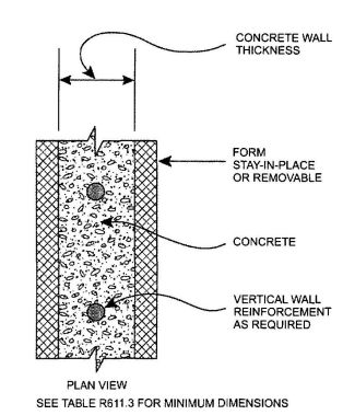
FIGURE R611.3(1)
FLAT WALL SYSTEM
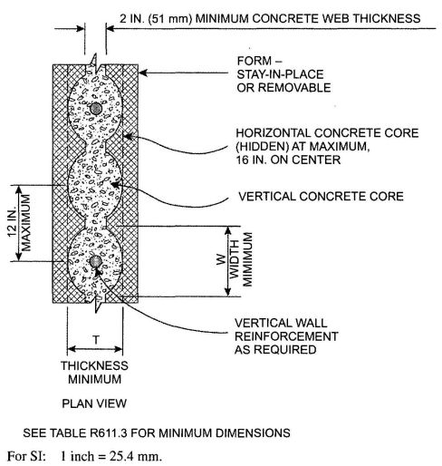
FIGURE R611.3(2)
WAFFLE-GRID WALL SYSTEM
R611.4.2 Interior covering. Stay-in-place forms constructed of rigid foam plastic shall be protected on the interior of the building as required by Section R316.4 and R702.3.4. Where gypsum board is used to protect the foam plastic, it shall be installed with a mechanical fastening system. Use of adhesives is permitted in addition to mechanical fasteners.
R611.4.3 Exterior wall covering. Stay-in-place forms constructed of rigid foam plastics shall be protected from sunlight and physical damage by the application of an approved exterior wall covering complying with this code. Exterior surfaces of other stay-in-place forming systems shall be protected in accordance with this code.
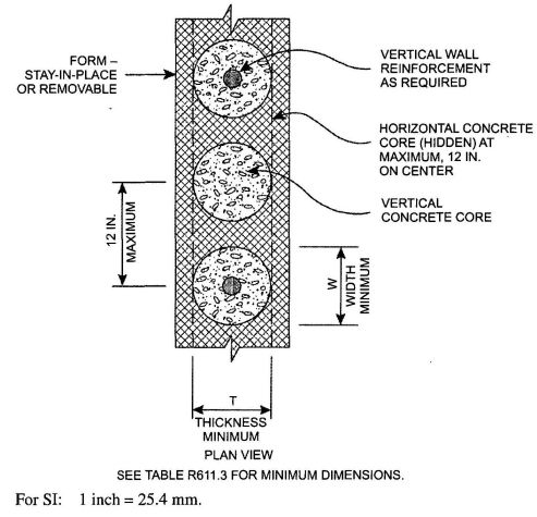
FIGURE R611.3(3)
SCREEN-GRID WALL SYSTEM
Requirements for installation of masonry veneer, stucco and other finishes on the exterior of concrete walls and other construction details not covered in this section shall comply with the requirements of this code.
R611.5 Materials. Materials used in the construction of concrete walls shall comply with this section.
R611.5.1 Concrete and materials for concrete. Materials used in concrete, and the concrete itself, shall conform to requirements of this section, or ACI 318.
R611.5.1.1 Concrete mixing and delivery. Mixing and delivery of concrete shall comply with ASTM C 94 or ASTM C 685.
R611.5.1.2 Maximum aggregate size. The nominal maximum size of coarse aggregate shall not exceed one-fifth the narrowest distance between sides of forms, or three-fourths the clear spacing between reinforcing bars or between a bar and the side of the form.
Exception: When approved, these limitations shall not apply where removable forms are used and workability and methods of consolidation permit concrete to be placed without honeycombs or voids.
R611.5.1.3 Proportioning and slump of concrete. Proportions of materials for concrete shall be established to provide workability and consistency to permit concrete to be worked readily into forms and around reinforcement under conditions of placement to be employed, without segregation or excessive bleeding. Slump of concrete placed in removable forms shall not exceed 6 inches (152 mm).
330Exception: When approved, the slump is permitted to exceed 6 inches (152 mm) for concrete mixtures that are resistant to segregation, and are in accordance with the form manufacturer’s recommendations.
Slump of concrete placed in stay-in-place forms shall exceed 6 inches (152 mm). Slump of concrete shall be determined in accordance with ASTM C 143.
R611.5.1.4 Compressive strength. The minimum specified compressive strength of concrete, fc, shall comply with Section R402.2 and shall be not less than 2,500 pounds per square inch (17.2 MPa) at 28 days.
R611.5.1.5 Consolidation of concrete. Concrete shall be consolidated by suitable means during placement and shall be worked around embedded items and reinforcement and into corners of forms. Where stay-in-place forms are used, concrete shall be consolidated by internal vibration.
Exception: When approved,self-consolidating concrete mixtures with slumps equal to or greater than 8 inches (203 mm) that are specifically designed for placement without internal vibration need not be internally vibrated.
R611.5.2 Steel reinforcement and anchor bolts.
R611.5.2.1 Steel reinforcement. Steel reinforcement shall comply with ASTM A 615, A 706, or A 996. ASTM A 996 bars produced from rail steel shall be Type R.
R611.5.2.2 Anchor bolts. Anchor bolts for use with connection details in accordance with Figures R611.9(1) through R611.9(12) shall be bolts with heads complying with ASTM A 307 or ASTM F 1554. ASTM A 307 bolts shall be Grade A (i.e., with heads). ASTM F 1554 bolts shall be Grade 36 minimum. Instead of bolts with heads, it is permissible to use rods with threads on both ends fabricated from steel complying with ASTM A 36. The threaded end of the rod to be embedded in the concrete shall be provided with a hex or square nut.
R611.5.2.3 Sheet steel angles and tension tie straps. Angles and tension tie straps for use with connection details in accordance with Figures R611.9(1) through R611.9(12) shall be fabricated from sheet steel complying with ASTM A 653 SS, ASTM A 792 SS, or ASTM A 875 SS. The steel shall be minimum Grade 33 unless a higher grade is required by the applicable figure.
R611.5.3 Form materials and form ties. Forms shall be made of wood, steel, aluminum, plastic, a composite of cement and foam insulation, a composite of cement and wood chips, or other approved material suitable for supporting and containing concrete. Forms shall provide sufficient strength to contain concrete during the concrete placement operation.
Form ties shall be steel, solid plastic, foam plastic, a composite of cement and wood chips, a composite of cement and foam plastic, or other suitable material capable of resisting the forces created by fluid pressure of fresh concrete.
R611.5.4 Reinforcement installation details.
R611.5.4.1 Support and cover. Reinforcement shall be secured in the proper location in the forms with tie wire or other bar support system such that displacement will not occur during the concrete placement operation. Steel reinforcement in concrete cast against the earth shall have a minimum cover of 3 inches (76 mm). Minimum cover for reinforcement in concrete cast in removable forms that will be exposed to the earth or weather shall be 1 ½ inches (38 mm) for No. 5 bars and smaller, and 2 inches (50 mm) for No. 6 bars and larger. For concrete cast in removable forms that will not be exposed to the earth or weather, and for concrete cast in stay-in-place forms, minimum cover shall be ¾ inch (19 mm). The minus tolerance for cover shall not exceed the smaller of one-third the required cover and 3/8 inch (10 mm). See Section R611.5.4.4 for cover requirements for hooks of bars developed in tension.
R611.5.4.2 Location of reinforcement in walls. For location of reinforcement in foundation walls and above-grade walls, see Sections R404.1.2.3.7.2 and R611.6.5, respectively.
R611.5.4.3 Lap splices. Vertical and horizontal wall reinforcement required by Sections R611.6 and R611.7 shall be the longest lengths practical. Where splices are necessary in reinforcement, the length of lap splices shall be in accordance with Table R611.5.4(1) and Figure R611.5.4 (1). The maximum gap between noncontact parallel bars at a lap splice shall not exceed the smaller of one-fifth the required lap length and 6 inches (152 mm). See Figure R611.5.4(1).
R611.5.4.4 Development of bars in tension. Where bars are required to be developed in tension by other provisions of this code, development lengths and cover for hooks and bar extensions shall comply with Table R611.5.4(1) and Figure R611.5.4 (2). The development lengths shown in Table R611.5.4(1) also apply to bundled bars in lintels installed in accordance with Section R611.8.2.2.
R611.5.4.5 Standard hooks. Where reinforcement is required by this code to terminate with a standard hook, the hook shall comply with Figure R611.5.4(3).
R611.5.4.6 Webs of waffle-grid walls. Reinforcement, including stirrups, shall not be placed in webs of waffle-grid walls, including lintels. Webs are permitted to have form ties.
R611.5.4.7 Alternate grade of reinforcement and spacing. Where tables in Sections R404.1.2 and R611.6 specify vertical wall reinforcement based on minimum bar size and maximum spacing, which are based on Grade 60 (420 MPa) steel reinforcement, different size bars and/or bars made from a different grade of steel are permitted provided an equivalent area of steel per linear foot of wall is provided. Use of Table R611.5.4(2) is permitted to determine the maximum bar spacing for different bar sizes than specified in the tables and/or bars made from a different grade of steel. Bars shall not be spaced less than one-half the wall thickness, or more than 48 inches (1219 mm) on center.
R611.5.5 Construction joints in walls. Construction joints shall be made and located to not impair the strength of the wall. Construction joints in plain concrete walls, including walls required to have not less than No. 4 bars at 48 inches
331(1219 mm) on center by Section R611.6, shall be located at points of lateral support, and a minimum of one No. 4 bar shall extend across the construction joint at a spacing not to exceed 24 inches (610 mm) on center. Construction joint reinforcement shall have a minimum of 12 inches (305 mm) embedment on both sides of the joint. Construction joints in reinforced concrete walls shall be located in the middle third of the span between lateral supports, or located and constructed as required for joints in plain concrete walls.
Exception: Vertical wall reinforcement required by this code is permitted to be used in lieu of construction joint reinforcement, provided the spacing does not exceed 24 inches (610 mm), or the combination of wall reinforcement and No. 4 bars described above does not exceed 24 inches (610 mm).
R611.6 Above-grade wall requirements.
R611.6.1 General. The minimum thickness of load-bearing and nonload-bearing above-grade walls and reinforcement shall be as set forth in the appropriate table in this section based on the type of wall form to be used. Where the wall or building is not within the limitations of Section R611.2, design is required by the tables in this section, or the wall is not within the scope of the tables in this section, the wall shall be designed in accordance with ACI 318.
| BAR SIZE NO. |
YIELD STRENGTH OF STEEL, fy - psi (MPa) | ||
|---|---|---|---|
| 40,000 (280) | 60,000 (420) | ||
| Splice length or tension development length (inches) |
|||
| For SI: 1 inch = 25.4 mm, 1 degree = 0.0175 rad. | |||
| Lap splice length–tension | 4 | 20 | 30 |
| 5 | 25 | 38 | |
| 6 | 30 | 45 | |
| Tension development length for straight bar | 4 | 15 | 23 |
| 5 | 19 | 28 | |
| 6 | 23 | 34 | |
Tension development length for:
| |||
| 4 | 6 | 9 | |
| 5 | 7 | 11 | |
| 6 | 8 | 13 | |
| Tension development length for bar with 90-degree or 180-degree standard hook having less cover than required above. |
4 | 8 | 12 |
| 5 | 10 | 15 | |
| 6 | 12 | 18 | |
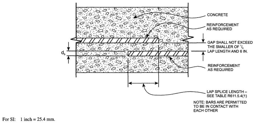
FIGURE R611.5.4(1)
LAP SPLICES
Above-grade concrete walls shall be constructed in accordance with this section and Figure R611.6(1), R611.6(2), R611.6(3), or R611.6(4). Above-grade concrete walls that are continuous with stem walls and not laterally supported by the slap-on-ground shall be designed and constructed in accordance with this section. Concrete walls shall be supported on continuous foundation walls or slabs-on-ground that are monolithic with the footing in accordance with Section R403. The minimum length of solid wall without openings shall be in accordance with Section R611.7. Reinforcement around openings, including lintels, shall be in accordance with Section R611.8. Lateral support for above-grade walls in the out-of-plane direction shall be provided by connections to the floor framing system, if applicable, and to ceiling and roof framing systems in accordance with Section R611.9. The wall thickness shall be equal to or greater than the thickness of the wall in the story above.
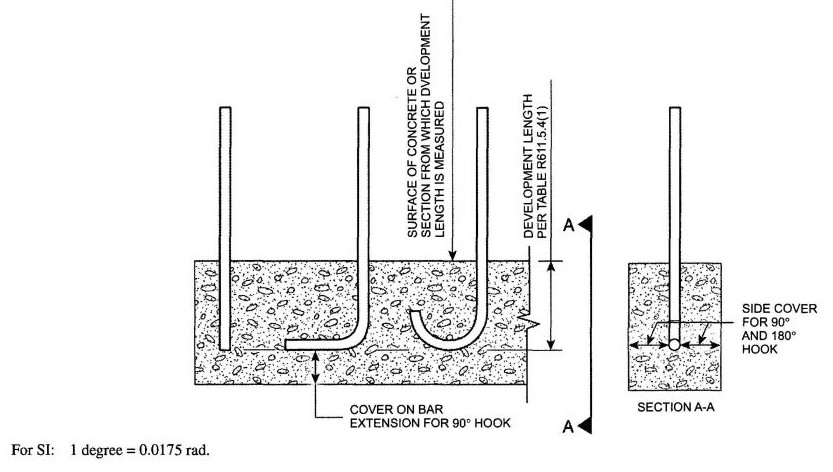
FIGURE R611.5.4(2)
DEVELOPMENT LENGTH AND COVER FOR HOOKS AND BAR EXTENSION
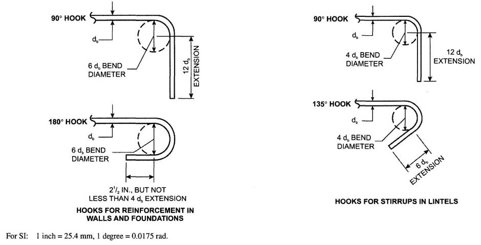
FIGURE R611.5.4(3)
STANDARD HOOKS
| BAR SPACING FROM APPLICABLE TABLE IN SECTION A611.6 (inches) |
BAR SIZE FROM APPLICABLE TABLE IN SECTION R611.6 (inches) | ||||||||||||||
|---|---|---|---|---|---|---|---|---|---|---|---|---|---|---|---|
| #4 | #5 | #6 | |||||||||||||
| Alternate bar size and/or alternate grade of steel desired | |||||||||||||||
| Grade 60 | Grade 40 | Grade 60 | Grade 40 | Grade 60 | Grade 40 | ||||||||||
| #5 | #6 | #4 | #5 | #6 | #4 | #6 | #4 | #5 | #6 | #4 | #5 | #4 | #5 | #6 | |
| Maximum spacing for alternate bar size and/or alternate grade of steel (inches) | |||||||||||||||
| For SI: 1 inch = 25.4 mm. | |||||||||||||||
| a. This table is for use with tables in Section R611.6 that specify the minimum bar size and maximum spacing of vertical wall reinforcement for foundation walls and above-grade walls. Reinforcement specified in tables in Section R611.6 is based on Grade 60 (420 MPa) steel reinforcement. | |||||||||||||||
| b. Bar spacing shall not exceed 48 inches on center and shall not be less than one-half the nominal wall thickness. | |||||||||||||||
| c. For Grade 50 (350 MPa) steel bars (ASTM A 996, Type R), use spacing for Grade 40 (280 MPa) bars or interpolate between Grade 40 (280 MPa) and Grade 60 (420 MPa). | |||||||||||||||
| 8 | 12 | 18 | 5 | 8 | 12 | 5 | 11 | 3 | 5 | 8 | 4 | 6 | 2 | 4 | 5 |
| 9 | 14 | 20 | 6 | 9 | 13 | 6 | 13 | 4 | 6 | 9 | 4 | 6 | 3 | 4 | 6 |
| 10 | 16 | 22 | 7 | 10 | 15 | 6 | 14 | 4 | 7 | 9 | 5 | 7 | 3 | 5 | 7 |
| 11 | 17 | 24 | 7 | 11 | 16 | 7 | 16 | 5 | 7 | 10 | 5 | 8 | 3 | 5 | 7 |
| 12 | 19 | 26 | 8 | 12 | 18 | 8 | 17 | 5 | 8 | 11 | 5 | 8 | 4 | 6 | 8 |
| 13 | 20 | 29 | 9 | 13 | 19 | 8 | 18 | 6 | 9 | 12 | 6 | 9 | 4 | 6 | 9 |
| 14 | 22 | 31 | 9 | 14 | 21 | 9 | 20 | 6 | 9 | 13 | 6 | 10 | 4 | 7 | 9 |
| 15 | 23 | 33 | 10 | 16 | 22 | 10 | 21 | 6 | 10 | 14 | 7 | 11 | 5 | 7 | 10 |
| 16 | 25 | 35 | 11 | 17 | 23 | 10 | 23 | 7 | 11 | 15 | 7 | 11 | 5 | 8 | 11 |
| 17 | 26 | 37 | 11 | 18 | 25 | 11 | 24 | 7 | 11 | 16 | 8 | 12 | 5 | 8 | 11 |
| 18 | 28 | 40 | 12 | 19 | 26 | 12 | 26 | 8 | 12 | 17 | 8 | 13 | 5 | 8 | 12 |
| 19 | 29 | 42 | 13 | 20 | 28 | 12 | 27 | 8 | 13 | 18 | 9 | 13 | 6 | 9 | 13 |
| 20 | 31 | 44 | 13 | 21 | 29 | 13 | 28 | 9 | 13 | 19 | 9 | 14 | 6 | 9 | 13 |
| 21 | 33 | 46 | 14 | 22 | 31 | 14 | 30 | 9 | 14 | 20 | 10 | 15 | 6 | 10 | 14 |
| 22 | 34 | 48 | 15 | 23 | 32 | 14 | 31 | 9 | 15 | 21 | 10 | 16 | 7 | 10 | 15 |
| 23 | 36 | 48 | 15 | 24 | 34 | 15 | 33 | 10 | 15 | 22 | 10 | 16 | 7 | 11 | 15 |
| 24 | 37 | 48 | 16 | 25 | 35 | 15 | 34 | 10 | 16 | 23 | 11 | 17 | 7 | 11 | 16 |
| 25 | 39 | 48 | 17 | 26 | 37 | 16 | 35 | 11 | 17 | 24 | 11 | 18 | 8 | 12 | 17 |
| 26 | 40 | 48 | 17 | 27 | 38 | 17 | 37 | 11 | 17 | 25 | 12 | 18 | 8 | 12 | 17 |
| 27 | 42 | 48 | 18 | 28 | 40 | 17 | 38 | 12 | 18 | 26 | 12 | 19 | 8 | 13 | 18 |
| 28 | 43 | 48 | 19 | 29 | 41 | 18 | 40 | 12 | 19 | 26 | 13 | 20 | 8 | 13 | 19 |
| 29 | 45 | 48 | 19 | 30 | 43 | 19 | 41 | 12 | 19 | 27 | 13 | 20 | 9 | 14 | 19 |
| 30 | 47 | 48 | 20 | 31 | 44 | 19 | 43 | 13 | 20 | 28 | 14 | 21 | 9 | 14 | 20 |
| 31 | 48 | 48 | 21 | 32 | 45 | 20 | 44 | 13 | 21 | 29 | 14 | 22 | 9 | 15 | 21 |
| 32 | 48 | 48 | 21 | 33 | 47 | 21 | 45 | 14 | 21 | 30 | 15 | 23 | 10 | 15 | 21 |
| 33 | 48 | 48 | 22 | 34 | 48 | 21 | 47 | 14 | 22 | 31 | 15 | 23 | 10 | 16 | 22 |
| 34 | 48 | 48 | 23 | 35 | 48 | 22 | 48 | 15 | 23 | 32 | 15 | 24 | 10 | 16 | 23 |
| 35 | 48 | 48 | 23 | 36 | 48 | 23 | 48 | 15 | 23 | 33 | 16 | 25 | 11 | 16 | 23 |
| 36 | 48 | 48 | 24 | 37 | 48 | 23 | 48 | 15 | 24 | 34 | 16 | 25 | 11 | 17 | 24 |
| 37 | 48 | 48 | 25 | 38 | 48 | 24 | 48 | 16 | 25 | 35 | 17 | 26 | 11 | 17 | 25 |
| 38 | 48 | 48 | 25 | 39 | 48 | 25 | 48 | 16 | 25 | 36 | 17 | 27 | 12 | 18 | 25 |
| 39 | 48 | 48 | 26 | 40 | 48 | 25 | 48 | 17 | 26 | 37 | 18 | 27 | 12 | 18 | 26 |
| 40 | 48 | 48 | 27 | 41 | 48 | 26 | 48 | 17 | 27 | 38 | 18 | 28 | 12 | 19 | 27 |
| 41 | 48 | 48 | 27 | 42 | 48 | 26 | 48 | 18 | 27 | 39 | 19 | 29 | 12 | 19 | 27 |
| 42 | 48 | 48 | 28 | 43 | 48 | 27 | 48 | 18 | 28 | 40 | 19 | 30 | 13 | 20 | 28 |
| 43 | 48 | 48 | 29 | 44 | 48 | 28 | 48 | 18 | 29 | 41 | 20 | 30 | 13 | 20 | 29 |
| 44 | 48 | 48 | 29 | 45 | 48 | 28 | 48 | 19 | 29 | 42 | 20 | 31 | 13 | 21 | 29 |
| 45 | 48 | 48 | 30 | 47 | 48 | 29 | 48 | 19 | 30 | 43 | 20 | 32 | 14 | 21 | 30 |
| 46 | 48 | 48 | 31 | 48 | 48 | 30 | 48 | 20 | 31 | 44 | 21 | 32 | 14 | 22 | 31 |
| 47 | 48 | 48 | 31 | 48 | 48 | 30 | 48 | 20 | 31 | 44 | 21 | 33 | 14 | 22 | 31 |
| 48 | 48 | 48 | 32 | 48 | 48 | 31 | 48 | 21 | 32 | 45 | 22 | 34 | 15 | 23 | 32 |
R611.6.2 Wall reinforcement for wind. Vertical wall reinforcement for resistance to out-of-plane wind forces shall be determined from Table R611.6(1), R611.6(2), R611.6(3) or R611.6(4). Also, see Sections R611.7.2.2.2 and R611.7.2.2.3. There shall be a vertical bar at all corners of exterior walls. Unless more horizontal reinforcement is required by Section R611.7.2.2.1, the minimum horizontal reinforcement shall be four No. 4 bars [Grade 40 (280 MPa)] placed as follows: top bar within 12 inches (305 mm) of the top of the wall, bottom bar within 12 inches (305 mm) of the finish floor, and one bar each at approximately one-third and two-thirds of the wall height.
R611.6.3 Continuity of wall reinforcement between stories. Vertical reinforcement required by this section shall be continuous between elements providing lateral support for the wall. Reinforcement in the wall of the storyabove shall be continuous with the reinforcement in the wall of the story below, or the foundation wall, if applicable. Lap splices, where required, shall comply with Section R611.5.4.3 and Figure R611.5.4(1). Where the above-grade wall is supported by a monolithic slab-on-ground and footing, dowel bars with a size and spacing to match the vertical above-grade concrete wall reinforcement shall be embedded in the monolithic slab-on-ground and footing the distance required to develop the dowel bar in tension in accordance with Section R611.5.4.4 and Figure R611.5.4(2) and lap-spliced with the above-grade wall reinforcement in accordance with Section R611.5.4.3 and Figure R611.5.4(1).
Exception: Where reinforcement in the wall above cannot be made continuous with the reinforcement in the wall below, the bottom of the reinforcement in the wall above shall be terminated in accordance with one of the following:
- Extend below the top of the floor the distance required to develop the bar in tension in accordance with Section R611.5.4.4 and Figure R611.5.4(2).
- Lap-spliced in accordance with Section R611.5.4.3 and Figure R611.5.4(1) with a dowel bar that extends into the wall below the distance required to develop the bar in tension in accordance with Section R611.5.4.4 and Figure R611.5.4(2).
Where a construction joint in the wall is located below the level of the floor and less than the distance required to develop the bar in tension, the distance required to develop the bar in tension shall be measured from the top of the concrete below the joint. See Section R611.5.5.
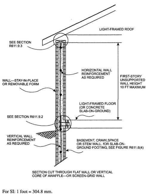
FIGURE R611.6(1)
ABOVE-GRADE CONCRETE WALL CONSTRUCTION ONE
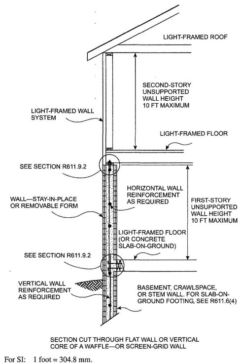
FIGURE R611.6(2)
ABOVE-GRADE CONCRETE WALL CONSTRUCTION
CONCRETE FIRST-STORY AND
LIGHT-FRAMED SECOND-STORY
R611.6.4 Termination of reinforcement. Where indicated in items 1 through 3 below, vertical wall reinforcement in the top-most story with concrete walls shall be terminated with a 90-degree (1.57 rad) standard hook complying with Section R611.5.4.5 and Figure R611.5.4(3).
The bar extension of the hook shall be oriented parallel to the horizontal wall reinforcement and be within 4 inches (102 mm) of the top of the wall.
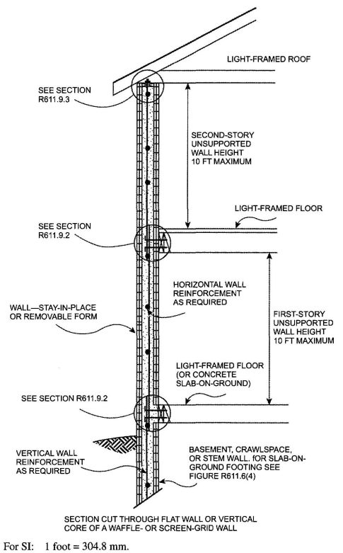
FIGURE R611.6(3)
ABOVE-GRADE CONCRETE WALL CONSTRUCTION TWO-STORY
Horizontal reinforcement shall be continuous around the building corners by bending one of the bars and lap-splicing it with the bar in the other wall in accordance with Section R611.5.4.3 and Figure R611.5.4(1).
Exception: In lieu of bending horizontal reinforcement at corners, separate bent reinforcing bars shall be permitted provided that the bent bar is lap-spliced with the horizontal reinforcement in both walls in accordance with Section R611.5.4.3 and Figure R611.5.4(1).
In required solid wall segments where the reduction factor for design strength, R3 is based on the wall having horizontal and vertical shear reinforcement in accordance with Section R611.7.2.2.1. horizontal wall reinforcement shall be terminated with a standard hook complying with Section R611.5.4.5 and Figure R611.5.4(3) or in a lap-splice, except at corners where the reinforcement shall be continuous as required above.
R611.6.5 Location of reinforcement in wall. Except for vertical reinforcement at the ends of required solid wall segments, which shall be located as required by Section R611.7.2.2, the location of the vertical reinforcement shall not vary from the center of the wall by more than the greater of 10 percent of the wall thickness and 3/8-inch (10 mm). Horizontal and vertical reinforcement shall be located to provide not less than the minimum cover required by Section R611.5.4.1.
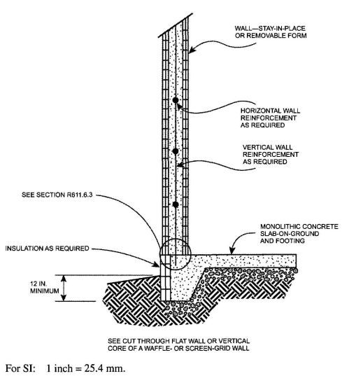
FIGURE R611.6(4)
ABOVE-GRADE CONCRETE WALL SUPPORTED ON MONOLITHIC SLAB-ON GROUND FOOTING
| MAXIMUM WIND SPEED (mph) | MAXIMUM UNSUPPORTED WALL HEIGHT PER STORY (feet) | MINIMUM VERTICAL REINFORCEMENT—BAR SIZE AND SPACING (inches)f,g | |||||||||
|---|---|---|---|---|---|---|---|---|---|---|---|
| Nominalh wall thickness (inches) | |||||||||||
| Exposure Category | 4 | 6 | 8 | 10 | |||||||
| B | C | D | Top1 | Side1 | Top1 | Side1 | Top1 | Side1 | Top1 | Side1 | |
| For SI:1 inch= 25.4 mm; 1 foot = 304.8 mm; 1 mile per hour = 0.447 m/s, 1 pound per square inch = 1.895kPa. | |||||||||||
| a. Table is based on ASCE 7 components and cladding wind pressures for an enclosed building a using a mean root height of 35 ft, interior wall area 4, an effective wind area of 10 ft2 and topographpic factor, Kzv and importance factor, I, equal to 1.0. | |||||||||||
| b. Table is based on concrete with a minimum specified compressive strength of 2,500 psi. | |||||||||||
| c. See Section R611.6.5 for location of reinforcement in wall. | |||||||||||
| d. Deflection criterion is L/240, where L is the unsupported height of the wall in inches. | |||||||||||
| e. Interpolation is not permitted. | |||||||||||
| f. Where No. 4 reinforcing bars at a spacing of 48 inches are specified in the table, use of bars with a minimum yield strength of 40,000 psi or 60,000 psi is permitted. | |||||||||||
| g. Other than for No. 4 bars spacing at 48 inches are specified in the table, use of bars with a minimum yield strength of 60,000 psi. Vertical reinforcement with a yield strength of less than 60,000 psi and/or bars of a different size than specified in the table are permitted in accordance with Section R611.5.4.7 and Table R611.5.4(2). | |||||||||||
| h. See Table R611.3 for tolerances on nominal thicknesses. | |||||||||||
| i. Top means gravity load from roof and/or floor construction bears on top of wall. Side means gravity load from floor construction is transferred to wall from a wood ledger or cold-formed steel track bolted to side of wall. Where floor framing members span parallel to the wall, use of the top bearing condition is permitted. | |||||||||||
| 85 | — | — | 8 | 4@48 | 4@48 | 4@48 | 4@48 | 4@48 | 4@48 | 4@48 | 4@48 |
| 9 | 4@48 | 4@43 | 4@48 | 4@48 | 4@48 | 4@48 | 4@48 | 4@48 | |||
| 10 | 4@47 | 4@36 | 4@48 | 4@48 | 4@48 | 4@48 | 4@48 | 4@48 | |||
| 90 | — | — | 8 | 4@48 | 4@47 | 4@48 | 4@48 | 4@48 | 4@48 | 4@48 | 4@48 |
| 9 | 4@48 | 4@39 | 4@48 | 4@48 | 4@48 | 4@48 | 4@48 | 4@48 | |||
| 10 | 4@42 | 4@48 | 4@48 | 4@48 | 4@48 | 4@48 | 4@48 | 4@48 | |||
| 100 | 85 | — | 8 | 4@48 | 4@40 | 4@48 | 4@48 | 4@48 | 4@48 | 4@48 | 4@48 |
| 9 | 4@42 | 4@34 | 4@48 | 4@48 | 4@48 | 4@48 | 4@48 | 4@48 | |||
| 10 | 4@34 | 4@34 | 4@34 | 4@48 | 4@48 | 4@48 | 4@48 | 4@48 | |||
| 110 | 90 | 85 | 8 | 4@44 | 4@34 | 4@48 | 4@48 | 4@48 | 4@48 | 4@48 | 4@48 |
| 9 | 4@34 | 4@34 | 4@48 | 4@48 | 4@48 | 4@48 | 4@48 | 4@48 | |||
| 10 | 4@34 | 4@31 | 4@48 | 4@37 | 4@48 | 4@48 | 4@48 | 4@48 | |||
| 120 | 100 | 90 | 8 | 4@36 | 4@34 | 4@48 | 4@48 | 4@48 | 4@48 | 4@48 | 4@48 |
| 9 | 4@34 | 4@32 | 4@34 | 4@32 | 4@48 | 4@38 | 4@48 | 4@48 | |||
| 10 | 4@30 | 4@27 | 4@48 | 5@48 | 4@48 | 4@48 | 4@48 | 4@48 | |||
| 130 | 110 | 100 | 8 | 4@34 | 4@34 | 4@48 | 4@48 | 4@48 | 4@48 | 4@48 | 4@48 |
| 9 | 4@32 | 4@28 | 4@48 | 4@33 | 4@48 | 4@48 | 4@48 | 4@48 | |||
| 10 | 4@26 | 4@23 | 4@48 | 5@43 | 4@48 | 4@48 | 4@48 | 4@48 | |||
| MAXIMUM WIND SPEED(mph) | MAXIMUM UNSUPPORTED WALL HEIGHT PER STORY (feet) | MINIMUM VERTICAL REINFORCEMENT—BAR SIZE AND SPACING (inches)f,g | |||||
|---|---|---|---|---|---|---|---|
| Nominalh wall thickness (inches) | |||||||
| Exposure Category | 6 | 8 | |||||
| B | C | D | Top1 | Side1 | Top1 | Side1 | |
| For SI: 1 inch = 25.4 mm: 1 foot = 304.8 mm, 1 mile per hour = 0.447 m/s, 1 pound per square inch = 6.895kPa. | |||||||
| a. Table is based on ASCE 7 components and cladding wind pressures for an enclosed building using a mean roof height of 35 ft (10668 mm), interior wall area 4, an effective wind area of 10 ft (0.9 m2) and topographic factor, Kzvand importance factor, 1, equal to 1.0. | |||||||
| b. Table is based on concrete with a minimum specified compressive strength of 2,500 psi (17.2 MPa). | |||||||
| c. See Section R611.6.5 for location of reinforcement in wall. | |||||||
| d. Deflection criterion is L/240, where L is the unsupported height of the wall in inches. | |||||||
| e. Interpolation is not permitted. | |||||||
| f. Where No. 4 reinforcing bars spaced at a spacing of 48 inches are specified in the table, use of bars with a minimum yield strength of 40,000 psi or 60,000 psi is permitted. | |||||||
| g. Other than for No. 4 bars spaced at 48 inches on center, table values are based on reinforcing bars with a minimum yield strength of 60,000 psi. Minimum spacings shown are the values calculated for the specified bar size. Where the bar used is Grade 60 (420 MPa) and the size specified in the table, the actual spacing in the wall shall not exceed a whole-number exceed a whole-number multiple of 12 inches (i.e., 12,24,36 and 48) that is less than or equal to the tabulated area spacing. Vertical reinforcement with a yield strength of less than 60,000 psi and/or bars of a different size than specified in the table are permitted in accordance with Section R611.5.4.7 and Table R11.5.4(2). | |||||||
| h. See Table R611.3 for minimum core dimensions and maximum spacing of horizontal and vertical cores. | |||||||
| i. Top means gravity load from roof and/or floor construction bears on top of wall. Side means gravity load from floor construction is transferred to wall from a wood ledger or cold-formed steel track bolted to side of wall. Where floor framing members span parallel to the wall, the top bearing condition is a permitted to be used. | |||||||
| 85 | — | — | 8 | 4@48 | 4@36,5@48 | 4@48 | 4@48 |
| 9 | 4@48 | 4@30,5@47 | 4@48 | 4@45 | |||
| 10 | 4@48 | 4@26,5@40 | 4@48 | 4@39 | |||
| 90 | — | — | 8 | 4@48 | 4@33,5@48 | 4@48 | 4@48 |
| 9 | 4@48 | 4@28,5@43 | 4@48 | 4@42 | |||
| 10 | 4@31,5@48 | 4@24,5@37 | 4@48 | 4@36 | |||
| 100 | 85 | — | 8 | 4@48 | 4@28,5@44 | 4@48 | 4@36 |
| 9 | 4@31, | 5@48,5@37 | 4@48 | 4@36 | |||
| 10 | 4@25,5@39 | 4@24,5@37 | 4@48 | 4@31,5@48 | |||
| 110 | 90 | 85 | 8 | 4@33,5@48 | 4@25,5@38 | 4@48 | 4@38 |
| 9 | 4@26,5@40 | 4@24,5@37 | 4@48 | 4@31,5@48 | |||
| 10 | 4@24,5@37 | 4@23,5@35 | 4@48 | 4@27,5@41 | |||
| 120 | 100 | 90 | 8 | 4@27,5@42 | 4@24,5@37 | 4@48 | 4@33,5@48 |
| 9 | 4@24,5@37 | 4@23,5@36 | 4@48 | 4@27,5@43 | |||
| 10 | 4@23,5@35 | 4@19,5@30 | 4@48 | 4@23,5@36 | |||
| 130 | 110 | 100 | 8 | 4@24,5@37 | 4@24,5@37 | 4@48 | 4@29,5@45 |
| 9 | 4@24,5@37 | 4@20,5@32 | 4@20,54 | 4@24,5@37 | |||
| 10 | 4@19.5@30 | 4@17,5@26 | 4@23,5@36 | 4@20,5@31 | |||
| MAXIMUM WIND SPEED (mph) | MAXIMUM UNSUPPORTED WALL HEIGHT PER STORY (feet) | MINIMUM VERTICAL REINFORCEMENT—BAR SIZE AND SPACING (inches)f,g | |||
|---|---|---|---|---|---|
| Nominalh wall thickness (inches) | |||||
| Exposure Category | 6 | ||||
| B | C | D | Top1 | Side1 | |
| For SI: 1 inch = 25.4 mm; 1 foot = 304.8 mm; 1 mph = 0.447 m/s, pound per square inch = 6.895kPa. | |||||
| a. Table is based on ASCE 7 components and cladding wind pressures for an enclosed building using a means roof height of 35 ft, interior wall area 4, an effective wind, area of 10 ft2 and topographic factor, K1 and importance factor, 1 equal to 1.0. | |||||
| b. Table is based on concrete with a minimum specified compressive strength of 2,500 psi. | |||||
| c. See Section R611.6.5 for location of reinforcement in wall. | |||||
| d. Deflection criterion is L/240, where L is the unsupported height of the wall in inches. | |||||
| e. Interpolation is not permitted. | |||||
| f. Where No. 4 reinforcing bars at a spacing of 48 inches are specified in the table, use of bars with a minimum yield strength of 40,000 psi or 60,000 psi permitted. | |||||
| g. Other than for No. 4 bars spaced at 48 inches on center, table values are based on reinforcing bars with a minimum yield strength of 60,000 psi (420 MPa). Maximum spacings shown are the values calculated for the specified bar size. Where the bar used in Grade 60 and the size specified in the table, the actual spacing in the wall shall not exceed a whole-number multiple of 12 inches (i.e., 12,24, 36 and 48) that is less than or equal to the tabulated spacing. Vertical reinforcement with a yield strength of less than 60,000 psi and/or bars of a different size than specified in the table are permitted in accordance with Section R611.5.4.7 and Table R611.5.4(2). | |||||
| h. See Table R611.3 for minimum core dimensions and maximum spacing of horizontal and vertical cores. | |||||
| i. Top means gravity load from roof and/or floor construction bears on top of wall. Side means gravity load from floor construction is transferred to wall from a wind ledger or cold-formed steel track boltes to side of wall. Where floor framing members span parallel to the wall, use of the top bearing condition is permitted. | |||||
| 85 | — | — | 8 | 4@48 | 4@34,5@48 |
| 9 | 4@48 | 4@29,5@45 | |||
| 10 | 4@48 | 4@25,5@39 | |||
| 90 | — | — | 8 | 4@48 | 4@31,5@48 |
| 9 | 4@48 | 4@27,5@41 | |||
| 10 | 4@30,5@47 | 4@23,5@35 | |||
| 100 | 85 | — | 8 | 4@48 | 4@27,5@42 |
| 9 | 4@30,5@47 | 4@23,5@35 | |||
| 10 | 4@24,5@38 | 4@22,5@34 | |||
| 110 | 90 | 85 | 8 | 4@48 | 4@24,5@37 |
| 9 | 4@25,5@38 | 4@22,5@34 | |||
| 10 | 4@22,5@34 | 4@22,5@34 | |||
| 120 | 100 | 90 | 8 | 4@26,5@41 | 4@22,5@34 |
| 9 | 4@22,5@34 | 4@22,5@34 | |||
| 10 | 4@22,6@34 | 4@19,5@26 | |||
| 130 | 110 | 100 | 8 | 4@22,5@35 | 4@22,5@34 |
| 9 | 4@22,5@34 | 4@20,5@30 | |||
| 10 | 4@19,5@29 | 4@16,5@25 | |||
| MAXIMUM WIND SPEED (mph) | HEIGHT OF STEM WALLh,i (feet) | MAXIMUM DESIGN LATERAL SOIL LOAD (psi/ft) | MAXIMUM UNSUPPORTED HEIGHT OF ABOVE-GRADE WALL (feet) | MINIMUM VERTICAL REINFORCEMENT—BAR SIZE AND SPACING (inches)f,g | ||||||||
|---|---|---|---|---|---|---|---|---|---|---|---|---|
| Wall type and nominal thicknessi(inches) | ||||||||||||
| Exposure Category | Flat | Waffle | Screen | |||||||||
| B | C | D | 4 | 6 | 8 | 10 | 6 | 8 | 6 | |||
| For SI: 1 inch = 25.4 mm; 1 foot = 304.8 mm; 1 mile per hour = 0.447 m/s; 1 pound per square foot per foot = 0.1571kPa/m. | ||||||||||||
| a. Table is based on ASCE 7 components and cladding wind pressures for an enclosed building using a mean roof height of 35 ft (10668 mm), interior wall area 4, an effective wind area of 10 ft2 and topographic factor K1 and importance factor, I, equal to 1.0. | ||||||||||||
| b. Table is based on concrete with a minimum specified compressive strength of 2,500 psi. | ||||||||||||
| c. See Section R611.6.5 for location of reinforcement in wall. | ||||||||||||
| d. Deflection criterion is L/240, where L is the height of the wall in inches from the exterior finish ground level to the top of the above-grade wall. | ||||||||||||
| e. Interpolation is not permitted. For intermediate values of basic wind speed, heights of stem wall and above-grade wall, and design lateral soil load, use next higher value. | ||||||||||||
| f. Where No. 4 reinforcing bars at a spacing of 48 inches are specified in the table, use of bars with a minimum yield strength of 40,000 psi or 60,000 psi is permitted. | ||||||||||||
| g. Other than for No. 4 bars spaced at 48 inches on center, table values are based on reinforcing bars with a minimum yield strength of 60,000 psi. Maximum spacings shown are the values calculated for the specified bar size. In waffle and screen-grid walls where the bar used is Grade 60 and the size specified in the table, the actual spacing in the wall shall not exceed a whole-number multiple of 12 inches (i.e., 12, 24, 36 and 48) that is less than or equal to the tabulated spacing. Vertical reinforcement with a yield strength of less than 60,000 psi and/or bars of a different size than specified in the table are permitted in accordance with Section R611.5.4.7 and Table R611.5.4(2). | ||||||||||||
| h. Height of stem wall is the distance from the exterior finish ground level to the top of the slab-on-ground. | ||||||||||||
| i. Where the distance from the exterior finish ground level to the top of the slab-on-ground is equal to or greater than 4 feet, the stem wall shall be laterally supported at the top and bottom before backfilling. Where the wall is designed and constructed to be continuous with the above-grade wall, temporary, supports bracing the top of the stem wall shall remain in place until the above-grade wall is laterally supported at the top by floor or roof construction. | ||||||||||||
| j. See Table R611.3 for tolerances on nominal thickness, and minimum core dimensions and maximum spacing of horizontal and vertical cores for waffle and screen-grid walls. | ||||||||||||
| k. Tabulated values are applicable to construction where gravity loads bear on top of wall, and conditions where gravity loads from floor construction are transferred to wall from a wood ledger or cold-formed steel track bolted to side of wall. See Tables R611.6(1), R611.6(2) and R611.6(3). | ||||||||||||
| l. DR indicates design required. | ||||||||||||
| 85 | — | — | 3 | 30 | 8 | 4@33 | 4@39 | 4@48 | 4@48 | 4@24 | 4@28 | 4@22 |
| 10 | 4@26 | 5@48 | 4@41 | 4@48 | 4@19 | 4@22 | 4@18 | |||||
| 60 | 10 | 4@21 | 5@40 | 5@48 | 4@44 | 4@16 | 4@19 | 4@15 | ||||
| 6 | 30 | 10 | DR | 5@22 | 6@35 | 6@43 | DR | 4@11 | DR | |||
| 60 | 10 | DR | DR | 6@26 | 6@28 | DR | DR | DR | ||||
| 90 | — | — | 3 | 30 | 8 | 4@30 | 4@36 | 4@48 | 4@48 | 4@22 | 4@26 | 4@21 |
| 10 | 4@24 | 5@44 | 4@38 | 4@48 | 4@17 | 4@21 | 4@17 | |||||
| 60 | 10 | 4@20 | 5@37 | 4@48 | 4@41 | 4@15 | 4@18 | 4@14 | ||||
| 6 | 30 | 10 | DR | 5@21 | 6@35 | 6@41 | DR | 4@10 | DR | |||
| 60 | 10 | DR | DR | 6@26 | 6@28 | DR | DR | DR | ||||
| 100 | 85 | — | 3 | 30 | 8 | 4@26 | 5@48 | 4@42 | 4@48 | 4@19 | 4@23 | 4@18 |
| 10 | 4@20 | 5@37 | 4@33 | 4@41 | 4@15 | 4@18 | 4@14 | |||||
| 6 | 60 | 10 | 4@17 | 5@34 | 5@44 | 4@36 | 4@13 | 4@17 | 4@12 | |||
| 30 | 10 | DR | 5@20 | 6@35 | 6@38 | DR | 4@9 | DR | ||||
| 60 | 10 | DR | DR | 6@24 | 6@28 | DR | DR | DR | ||||
| 110 | 90 | 85 | 3 | 30 | 8 | 4@22 | 5@42 | 4@37 | 4@46 | 4@16 | 4@20 | 4@16 |
| 10 | 4@17 | 5@34 | 5@44 | 4@35 | 4@12 | 4@17 | 4@12 | |||||
| 60 | 10 | 4@15 | 5@34 | 5@39 | 5@48 | 4@11 | 4@17 | 4@11 | ||||
| 6 | 30 | 10 | DR | 5@18 | 6@35 | 6@35 | DR | 4@9 | DR | |||
| 60 | 10 | DR | DR | 6@23 | 6@28 | DR | DR | DR | ||||
| 120 | 100 | 90 | 3 | 30 | 8 | 4@19 | 5@37 | 5@48 | 4@40 | 4@14 | 4@17 | 4@14 |
| 10 | 4@14 | 5@34 | 5@38 | 5@48 | 4@11 | 4@17 | 4@10 | |||||
| 60 | 10 | 4@13 | 5@33 | 6@48 | 5@43 | 4@10 | 4@16 | 4@9 | ||||
| 6 | 30 | 10 | DR | 5@16 | 6@33 | 6@32 | DR | 4@8 | DR | |||
| 60 | 10 | DR | DR | 6@22 | 6@28 | DR | DR | DR | ||||
| 130 | 110 | 100 | 3 | 30 | 8 | 4@17 | 5@34 | 5@44 | 4@36 | 4@12 | 4@17 | 4@10 |
| 10 | DR | 5@32 | 6@47 | 5@42 | 4@9 | 4@15 | DR | |||||
| 60 | 10 | DR | 5@29 | 6@43 | 5@39 | DR | 4@14 | DR | ||||
| 6 | 30 | 10 | DR | 5@15 | 6@30 | 6@29 | DR | 4@7 | ||||
| 60 | 10 | DR | DR | 6@21 | 6@27 | DR | DR | DR | ||||
R611.7 Solid walls for resistance to lateral forces.
R611.7.1 Length of solid wall. Each exterior wall line in each story shall have a total length of solid wall required by Section R611.7.1.1. A solid wall is a section of flat, waffle-grid or screen-grid wall, extending the full story height without openings or penetrations, except those permitted by Section R611.7.2. Solid wall segments that contribute to the total length of solid wall shall comply with Section R611.7.2.
R611.7.1.1 Length of solid wall for wind. All buildings shall have solid walls in each exterior endwall line (the side of a building that is parallel to the span of the roof or floor framing) and sidewall line (the side of a building that is perpendicular to the span of the roof or floor framing) to resist lateral in-plane wind forces. The site-appropriate basic wind speed and exposure category shall be used in Tables R611.7(1A) through (1C) to determine the unreduced total length, UR, of solid wall required in each exterior endwall line and sidewall line. For buildings with a mean roof height of less than 35 feet (10 668 mm), the unreduced values determined from Tables R611.7(1A) through (1C) is permitted by multiplying by the applicable factor, R1, from Table R611.7(2); however, reduced values shall not be less than the minimum values in Tables R611.7(1A) through (1C). Where the floor-to-ceiling height of a story is less than 10 feet (3048 mm), the unreduced values determined from Tables R611.7(1A) through (C), including minimum values, is permitted to be reduced by multiplying by the applicable factor, R2, from Table R611.7(3). To account for different design strengths than assumed in determining the values in Tables R611.7(1A) through (1C), the unreduced lengths determined from Tables R611.7(1A) through (1C), including minimum values, are permitted to be reduced by multiplying by the applicable factor, R3, from Table R611.7(4). The reductions permitted by Tables R611.7(2), R611.7(3) and R611.7(4) are cumulative.
The total length of solid wall segments, TL, in a wall line that comply with the minimum length requirements of Section R611.7.2.1 [see Figure R611.7(1)] shall be equal to or greater than the product of the unreduced length of solid wall from Tables R611.7(1A) through (1C), UR and the applicable reduction factors, if any, from Tables R611.7(2), R611.7(3) and R611.7(4) as indicated by Equation R611-1.

Where
TL = total length of solid wall segments in a wall line that comply with Section R611.7.2.1 [see Figure R611.7(1)], and
R1 = 1.0 or reduction factor for mean roof height from Table R611.7(2),
R2 = 1.0 or reduction factor for floor-to-ceiling wall height from Table R611.7(3),
R3 = 1.0 or reduction factor for design strength from Table R611.7(4), and
UR = unreduced length of solid wall from Tables R611.7(1A) through (1C).
The total length of solid wall in a wall line, TL, shall not be less than that provided by two solid wall segments complying with the minimum length requirements of Section R611.7.2.1.
To facilitate determining the required wall thickness, wall type, number and grade of vertical bars at the each end of each solid wall segment, and whether shear reinforcement is required, use of Equation R611-2 is permitted.
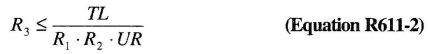
After determining the maximum permitted value of the reduction factor for design strength, R3, in accordance with Equation R611-2, select a wall type from Table R611.7(4) with R3 less than or equal to the value calculated.
R611.7.2 Solid wall segments. Solid wall segments that contribute to the required length of solid wall shall comply with this section. Reinforcement shall be provided in accordance with Section R611.7.2.2 and Table R611.7(4). Solid wall segments shall extend the full story-height without openings, other than openings for the utilities and other building services passing through the wall. In flat walls and waffle-grid walls, such openings shall have an area of less than 30 square inches (19 355 mm2) with no dimension exceeding 6¼ inches (159 mm), and shall not be located within 6 inches (152 mm) of the side edges of the solid wall segment. In screen-grid walls, such openings shall be located in the portion of the solid wall segments between horizontal and vertical cores of concrete and opening size and location are not restricted provided no concrete is removed.
R611.7.2.1 Minimum length of solid wall segment and maximum spacing. Only solid wall segments equal to or greater than 24 inches (610 mm) in length shall be included in the total length of solid wall required by Section R611.7.1. In addition, no more than two solid wall segments equal to or greater than 24 inches (610 mm) in length and less than 48 inches (1219 mm) in length shall be included in the required total length of solid wall. The maximum clear opening width shall be 18 feet (5486 mm). See Figure R611.7(1).
R611.7.2.2 Reinforcement in solid wall segments.
R611.7.2.2.1 Horizontal shear reinforcement. Where reduction factors for design strength, R3, from Table R611.7(4) based on horizontal and vertical shear reinforcement being provided are used, solid wall segments shall have horizontal reinforcement
consisting of minimum No. 4 bars. Horizontal shear reinforcement shall be the same grade of steel required for the vertical reinforcement at the ends of solid wall segments by Section R611.7.2.2.2.
The spacing of horizontal reinforcement shall not exceed the smaller of one-half the length of the solid wall segment, minus 2 inches (51 mm), and 18 inches (457 mm). Horizontal shear reinforcement shall terminate in accordance with Section R611.6.4.
R611.7.2.2.2 Vertical reinforcement. Vertical reinforcement applicable to the reduction factor(s) for design strength, R3, from Table R611.7(4) that is used, shall be located at each end of each solid wall segment in accordance with the applicable detail in Figure R611.7(2). The No. 4 vertical bar required on each side of an opening by Section R611.8.1.2 is permitted to be used as reinforcement at the ends of solid wall segments where installed in accordance with the applicable detail in Figure R611.7(2). There shall be not less than two No. 4 bars at each end of solid wall segments located as required by the applicable detail in Figure R611.7(2). One of the bars at each end of solid wall segments shall be deemed to meet the requirements for vertical wall reinforcement required by Section R611.6.
The vertical wall reinforcement at each end of each solid wall segment shall be developed below the bottom of the adjacent wall opening [see Figure R611.7(3)] by one of the following methods:
R611.7.2.2.3 Vertical shear reinforcement. Where reduction factors for design strength, R3, from Table R611.7(4) based on horizontal and vertical shear reinforcement being provided are used, solid wall segments shall have vertical reinforcement consisting of minimum No. 4 bars. Vertical shear reinforcement shall be the same grade of steel required by Section R611.7.2.2.2 for the vertical reinforcement at the ends of solid wall segments. The spacing of vertical reinforcement throughout the length of the segment shall not exceed the smaller of one third the length of the segment, and 18 inches (457 mm). Vertical shear reinforcement shall be continuous between stories in accordance with Section R611.6.3, and shall terminate in accordance with Section R611.6.4. Vertical shear reinforcement required by this section is permitted to be used for vertical reinforcement required by Table R611.6(1), R611.6(2), R611.6(3) or R611.6(4), whichever is applicable.
R611.7.2.3 Solid wall segments at corners. At all interior and exterior corners of exterior walls, a solid wall segment shall extend the full height of each wall story. The segment shall have the length required to develop the horizontal reinforcement above and below the adjacent opening in tension in accordance with Section R611.5.4.4. For an exterior corner, the limiting dimension is measured on the outside of the wall, and for an interior corner the limiting dimension is measured on the inside of the wall. See Section R611.8.1. The length of a segment contributing to the required length of solid wall shall comply with Section R611.7.2.1.
The end of a solid wall segment complying with the minimum length requirements of Section R611.7.2.1 shall be located no more than 6 feet (1829 mm) from each corner.
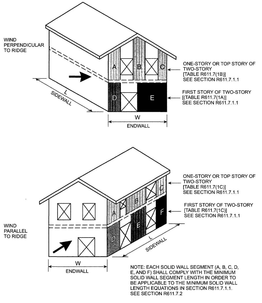
FIGURE R611.7(1)
MINIMUM SOLID WALL LENGTH
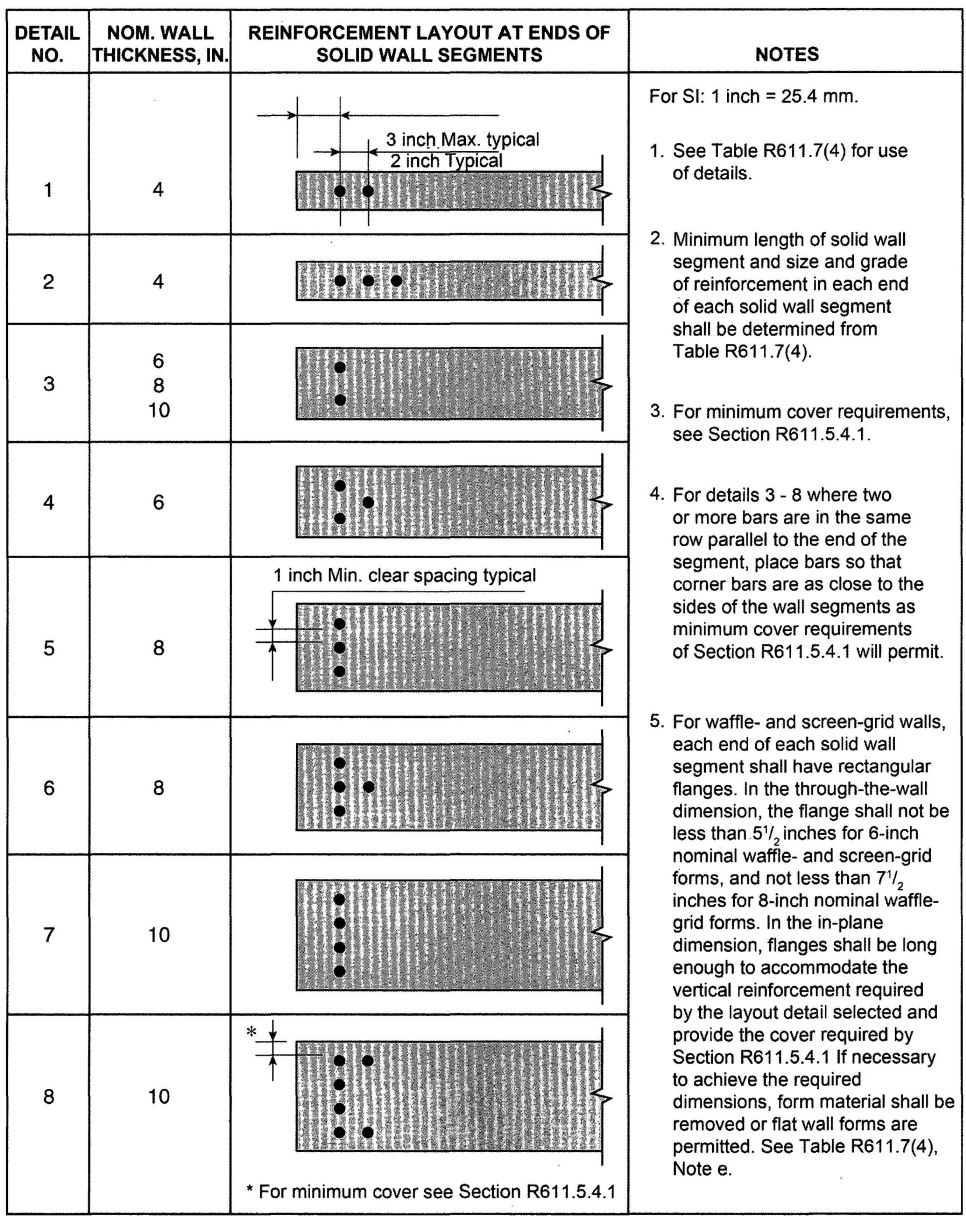
| MEAN ROOF HEIGHTb,c(feet) | REDUCTION FACTOR R1, FOR MEAN ROOF HEIGHT | ||
|---|---|---|---|
| Exposure category | |||
| B | C | D | |
| For SI: 1 foot = 304.8 mm. | |||
| a. See Section R611.7.1.1 and note c to Table R611.7(1A) for application of reduction factors in this table. This reduction is not permitted for “minimum” values. | |||
| b. For intermediate values of mean roof height, use the factor for the next greater height, or determine by interpolation. | |||
| c. Mean roof height is the average of the roof eave height and height of the highest point on the roof surface, except that for roof slopes of less than or equal to 2 1/8: 12 (10 degrees), the mean roof height is permitted to be taken as the roof eave height. | |||
| <15 | 0.96 | 0.84 | 0.87 |
| 20 | 0.96 | 0.89 | 0.91 |
| 25 | 0.96 | 0.93 | 0.94 |
| 30 | 0.96 | 0.97 | 0.98 |
| 35 | 1.00 | 1.00 | 1.00 |
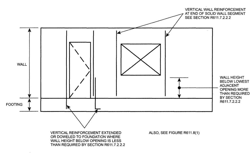
FIGURE R611.7(3)
VERTICAL WALL REINFORCEMENT ADJACENT TO WALL OPENINGS
| STORY UNDER CONSIDERATION | FLOOR-TO- CEILING HEIGHTc (feet) | ENDWALL LENGTH (feet) | ROOF SLOPE | REDUCTION FACTOR, R2 |
|---|---|---|---|---|
| Endwalls—for wind perpendicular to ridge | ||||
| For SI: 1 foot = 304.8 mm. | ||||
| a. See Section R611.7.1.1 and Note d to Table R611.7(1A) for application of reduction factors in this table. | ||||
| b. For intermediate values of endwall length, and/or roof slope. Use the next higher value, or determine by interpolation. | ||||
| c. Tabulated values in Table R611.7 (1A) and (1C) for “one story or top story of two-story” are based on a floor-to-ceiling height of 10 feet (3048 mm). Tabulated values in Table R611.7 (1B) and (1C) for “first story of two-story” are based on floor-to-ceiling heights of 10 feet each for the first and second story. For floor to ceiling heights between those shown in this table and those assumed in Table R611.7(1A),(1B) or (1C), use the solid wall lengths in Table R611.7(1A), (1B) or (1C), or determine the reduction factor by interpolating between 1.0 and the factor shown in this table. | ||||
| One story or top story of two-story |
8 | 15 | <5:12 | 0.83 |
| 7:12 | 0.90 | |||
| 12:12 | 0.94 | |||
| 60 | <5:12 | 0.83 | ||
| 7:12 | 0.95 | |||
| 12:12 | 0.98 | |||
| First story of two-story | 16 combined first and second story |
15 | <5:12 | 0.83 |
| 7:12 | 0.86 | |||
| 12:12 | 0.89 | |||
| 60 | <5:12 | 0.83 | ||
| 7:12 | 0.91 | |||
| 12:12 | 0.95 | |||
| Sidewalls—for wind parallel to ridge | ||||
| One story or top story of two-story |
8 | 15 | <1:12 | 0.84 |
| 5:12 | 0.87 | |||
| 7:12 | 0.88 | |||
| 12:12 | 0.89 | |||
| 60 | <1:12 | 0.86 | ||
| 5:12 | 0.92 | |||
| 7:12 | 0.93 | |||
| 12:12 | 0.95 | |||
| First story of two-story | 16 combined first and second story |
15 | <1:12 | 0.83 |
| 5:12 | 0.84 | |||
| 7:12 | 0.85 | |||
| 12:12 | 0.86 | |||
| 60 | <1:12 | 0.84 | ||
| 5:12 | 0.87 | |||
| 7:12 | 0.88 | |||
| 12:12 | 0.90 | |||
| NOMINAL THICKNESS OF WALL (inches) | VERTICAL BARS AT EACH END OF SOLID WALL SEGMENT | VERTICAL REINFORCEMENT LAYOUT DETAIL [see Figure R611.7(2)] | REDUCTION FACTORR3, FOR LENGTH OF SOLID WALL | ||||
|---|---|---|---|---|---|---|---|
| Horizontal and vertical shear reinforcement provided | |||||||
| Number of bars | Bar size | No | Yesd | ||||
| 40,000b | 60,000b | 40,000b | 60,000b | ||||
| Flat walls | |||||||
| For SI: 1 inch = 25.4 mm; 1,000 pounds per square inch = 6.895 MPa. | |||||||
| a. See note e to Table R611.7(1A) for application of adjustment factors in this table. | |||||||
| b. Yield strength in pounds per square inch of vertical wall reinforcement at ends of solid wall segments. | |||||||
| c. Values are based on concrete with a specified compressive strength f’c, of 2,500 psi. Where concrete with f’c of not less than 3,000 psi is used, values in shaded cells are permitted to be decreased by multiplying by 0.91. | |||||||
| d. Horizontal and vertical shear reinforcement shall be provided in accordance with Section R611.7.2.2. | |||||||
| e. Each end of each solid wall segment shall have rectangular flange. In the through-the-wall dimension, the flange shall not be less than 5½ inches for 6-inch nominal waffle-and screen-grid walls, and not less than 7½ inches for 8-inch nominal waffle-grid walls. In the in-plane dimension, flanges shall be long enough to accommodate the vertical reinforcement required by the layout detail selected from Figure R611.7(2) and provide the cover required by Section R611.5.4.1. If necessary to achieve the required dimensions, from material shall be removed of use of flat wall forms is permitted. | |||||||
| 4 | 2 | 4 | 1 | 0.74 | 0.61 | 0.74 | 0.50 |
| 3 | 4 | 2 | 0.61 | 0.61 | 0.52 | 0.27 | |
| 2 | 5 | 1 | 0.61 | 0.61 | 0.48 | 0.25 | |
| 3 | 5 | 2 | 0.61 | 0.61 | 0.26 | 0.18 | |
| 6 | 2 | 4 | 3 | 0.70 | 0.48 | 0.70 | 0.48 |
| 3 | 4 | 4 | 0.49 | 0.38 | 0.49 | 0.33 | |
| 2 | 5 | 3 | 0.46 | 0.38 | 0.46 | 0.31 | |
| 3 | 5 | 4 | 0.38 | 0.38 | 0.32 | 0.16 | |
| 8 | 2 | 4 | 3 | 0.70 | 0.47 | 0.70 | 0.47 |
| 3 | 4 | 5 | 0.47 | 0.32 | 0.47 | 0.32 | |
| 2 | 5 | 3 | 0.45 | 0.31 | 0.45 | 0.31 | |
| 4 | 4 | 6 | 0.36 | 0.28 | 0.36 | 0.25 | |
| 3 | 5 | 5 | 0.31 | 0.28 | 0.31 | 0.16 | |
| 4 | 5 | 6 | 0.28 | 0.28 | 0.24 | 0.12 | |
| 10 | 2 | 4 | 3 | 0.07 | 0.47 | 0.70 | 0.47 |
| 2 | 5 | 3 | 0.45 | 0.30 | 0.45 | 0.30 | |
| 4 | 4 | 7 | 0.36 | 0.25 | 0.36 | 0.25 | |
| 6 | 4 | 8 | 0.25 | 0.22 | 0.25 | 0.13 | |
| 4 | 5 | 7 | 0.24 | 0.22 | 0.24 | 0.12 | |
| 6 | 5 | 8 | 0.22 | 0.22 | 0.12 | 0.08 | |
| Waffle-grid wallse | |||||||
| 6 | 2 | 4 | 3 | 0.78 | 0.78 | 0.70 | 0.48 |
| 3 | 4 | 4 | 0.78 | 0.78 | 0.49 | 0.25 | |
| 2 | 5 | 3 | 0.78 | 0.78 | 0.46 | 0.23 | |
| 3 | 5 | 4 | 0.78 | 0.78 | 0.24 | 0.16 | |
| 8 | 2 | 4 | 3 | 0.78 | 0.78 | 0.70 | 0.47 |
| 3 | 4 | 5 | 0.78 | 0.78 | 0.47 | 0.24 | |
| 2 | 5 | 3 | 0.78 | 0.78 | 0.45 | 0.23 | |
| 4 | 4 | 6 | 0.78 | 0.78 | 0.36 | 0.18 | |
| 3 | 5 | 5 | 0.78 | 0.78 | 0.23 | 0.16 | |
| 4 | 5 | 6 | 0.78 | 0.78 | 0.18 | 0.13 | |
| Screen-grid wallse | |||||||
| 6 | 2 | 4 | 3 | 0.93 | 0.93 | 0.70 | 0.48 |
| 3 | 4 | 4 | 0.93 | 0.93 | 0.49 | 0.25 | |
| 2 | 5 | 3 | 0.93 | 0.93 | 0.46 | 0.23 | |
| 3 | 5 | 4 | 0.93 | 0.93 | 0.24 | 0.16 | |
R611.8 Requirements for lintels and reinforcement around openings.
R611.8.1 Reinforcement around openings. Reinforcement shall be provided around openings in walls equal to or greater than 2 feet (610 mm) in width in accordance with this section and Figure R611.8(1), in addition to the minimum wall reinforcement required by Sections R404.1.2, R611.6 and R611.7. Vertical wall reinforcement required by this section is permitted to be used as reinforcement at the ends of solid wall segments required by Section R611.7.2.2.2 provided it is located in accordance with Section R611.8.1.2. Wall openings shall have a minimum depth of concrete over the width of the opening of 8 inches (203 mm) in flat walls and waffle-grid walls, and 12 inches (305 mm) in screen-grid walls. Walls openings in waffle-grid and screen-grid walls shall be located such that not less than one-half of a vertical core occurs along each side of the opening.
R611.8.1.1 Horizontal reinforcement. Lintels complying with Section R611.8.2 shall be provided above wall openings equal to or greater than 2 feet (610 mm) in width.
Exception: Continuous horizontal wall reinforcement placed within 12 inches (305 mm) of the top of the wall storyas required in Sections R404.1.2.2 and R611.6.2 is permitted in lieu of top or bottom lintel reinforcement required by Section R611.8.2 provided that the continuous horizontal wall reinforcement meets the location requirements specified in Figures R611.8(2), R611.8(3), and R611.8(4) and the size requirements specified in Tables R611.8(2) through R611.8(10).
Openings equal to or greater than 2 feet (610 mm) in width shall have a minimum of one No. 4 bar placed within 12 inches (305 mm) of the bottom of the opening. See Figure R611.8(1).
Horizontal reinforcement placed above and below an opening shall extend beyond the edges of the opening the dimension required to develop the bar in tension in accordance with Section R611.5.4.4.
R611.8.1.2 Vertical reinforcement. Not less than one No.4 bar [Grade 40 (280 MPa)] shall be provided on each side of openings equal to or greater than 2 feet (610 mm) in width. The vertical reinforcement required by this section shall extend the full height of the wall storyand shall be located within 12 inches (305 mm) of each side of the opening. The vertical reinforcement required on each side of an opening by this section is permitted to serve as reinforcement at the ends of solid wall segments in accordance with Section R611.7.2.2.2, provided it is located as required by the applicable detail in Figure R611.7(2). Where the vertical reinforcement required by this section is used to satisfy the requirements of Section R611.7.2.2.2 in waffle-and screen-grid walls, a concrete flange shall be created at the ends of the solid wall segments in accordance with Table R611.7(4), note e. In the top-most story, the reinforcement shall terminate in accordance with Section R611.6.4.
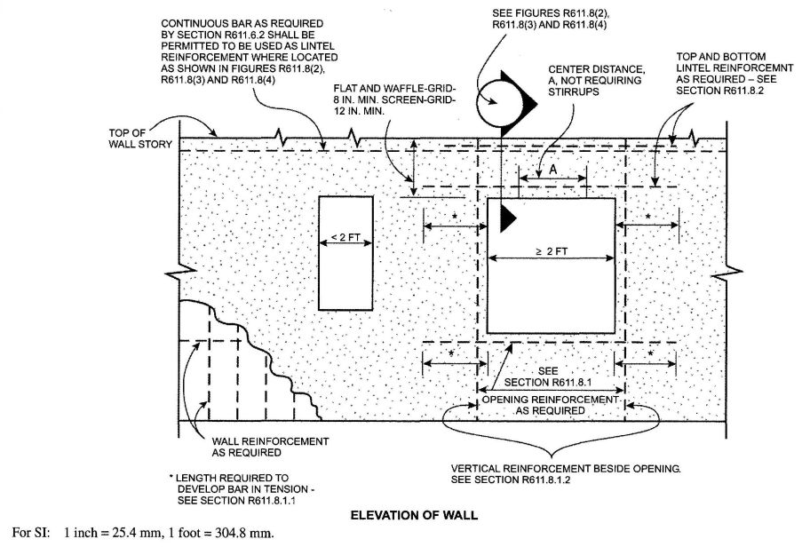
FIGURE R611.8(1)
REINFORCEMENT OF OPENINGS
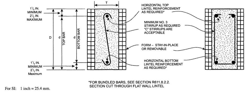
FIGURE R611.8(2)
LINTEL FOR FLAT WALLS
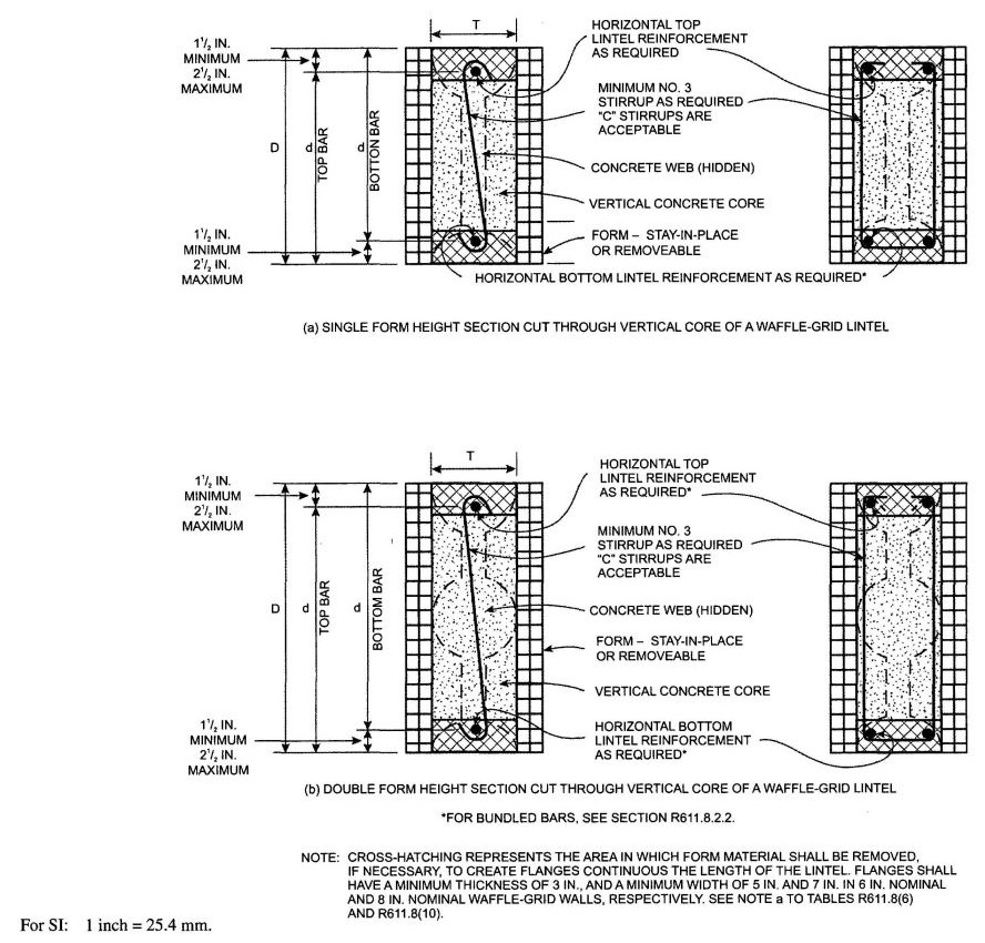
FIGURE R611.8(3)
LINTELS FOR WAFFLE-GRID WALLS
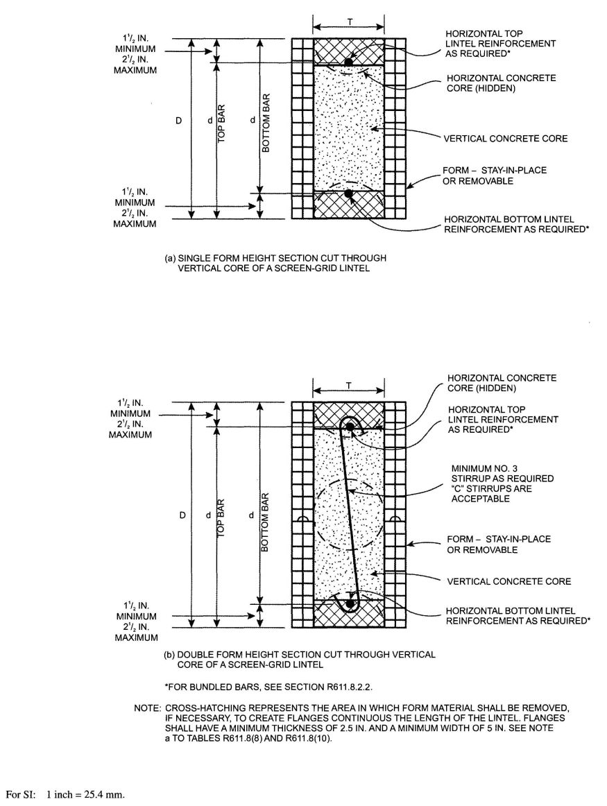
FIGURE R611.8(4)
LINTELS FOR SCREEN-GRID WALLS
R611.8.2 Lintels. Lintels shall be provided over all openings equal to or greater than 2 feet (610 mm) in width. Lintels with uniform loading shall conform to Sections R611.8.2.1, and R611.8.2.2, or Section R611.8.2.3, Lintels supporting concentrated loads, such as from roof or floor beans or griders, shall be designed in accordance with ACI 318.
R611.8.2.1 Lintels designed for gravity load-bearing conditions. Where a lintel will be subjected to gravity load condition 1 through 5 of Table R611.8(1), the clear span of the lintel shall not exceed that permitted by Tables R611.8(2) through R611.8(8). The maximum clear span of lintels with and without stirrups in flat walls shall be determined in accordance with Tables R611.8(2) through R611.8(5), and constructed in accordance with Figure R611.8(2). The maximum clear span of lintels with and without stirrups in waffle-grid walls shall be determined in accordance with Tables R611.8(6) and R611.8(7), and constructed in accordance with Figure R611.8(3). The maximum clear span of lintels with and without stirrups in screen-grid walls shall be determined in accordance with Table R611.8(8), and constructed in accordance with Figure R611.8(4).
Where required by the applicable table, No. 3 stirrups shall be installed in lintels at a maximum spacing of d/2 where d equals the depth of the lintel, D, less the cover of the concrete as shown in Figures R611.8(2) through R611.8(4). The smaller value of d computed for the top and bottom bar shall be used to determine the maximum stirrup spacing. Where stirrups are required in a lintel with a single bar or two bundled bars in the top and bottom, they shall be fabricated like the letter “c” or “s” with 135-degree (2.36 rad) standard hooks at each and that comply with Section R611.5.4.5 and Figure R611.5.4(3) and installed as shown in Figures R611.8(2) through R611.8(4). Where two bars are required in the top and bottom of the lintel and the bars are not bundled, the bars shall be separated by a minimum of 1 inch (25 mm). The free end of the stirrups shall be fabricated with 90- or 135-degree (1.57 or 2.36 rad) standard hooks that comply with Section R611.5.4.5 and Figure R611.5.4(3) and installed as shown in Figures R611.8(2) and R611.8(3). For flat, waffle-grid and screen-grid lintels, stirrups are not required in the center distance, A portion of spans in accordance with Figure R611.8(1) and Tables R611.8(2) through R611.8(8). See Section R611.8.2.2, item 5, for requirement for stirrups throughout lintels with bundled bars.
R611.8.2.2 Bundled bars in lintels. It is permitted to bundle two bars in contact with each other in lintels if all of the following are observed:
R611.8.2.3 Lintels without stirrups designed for nonload-bearing conditions. The maximum clear span of lintels without stirrups designed for nonload-bearing conditions of Table R611.8(1).1 shall be determined in accordance with this section. The maximum clear span of lintels without stirrups in flat walls shall be determined in accordance with Table R611.8(9), and the maximum clear span of lintels without stirrups in walls of waffle-grid or screen-grid construction shall be determined in accordance with Table R611.8(10).
| DESCRIPTION OF LOADS AND OPENINGS ABOVE INFLUENCING DESIGN OF LINTEL | DESIGN LOAD CONDITIONSc | ||
|---|---|---|---|
| Opening in wall of top story of two-story building, or first story of one-story building | |||
| a. LB means load bearing, NLB means nonload-bearing, and W means width of opening. | |||
| b. Footprint is the area of the wall below an opening in the story above, bounded by the bottom of the opening and vertical lines extending downward from the edges of the opening. | |||
| c. For design loading condition “NLB” see Table R611.8(9) and R611.8.(10). For all other design loading conditions see Tables R611.8(2) through R611.8(8). | |||
| d. A NLB ledger board is a ledger attached to a wall that is parallel to the span of the floor, roof or ceiling framing that supports the edge of the floor, ceiling or roof. | |||
| Wall supporting loads from roof, including attic floor, if applicable, and | Top of lintel equal to or less than W/2 below top of wall | 2 | |
| Top of lintel greater than W/2 below top of wall | NLB | ||
| Wall not supporting loads from roof or attic floor | NLB | ||
| Opening in wall of first story of two-story building where wall immediately above is of concrete construction, or opening in basement wall of one-story building where wall immediately above is of concrete construction |
|||
| LB ledger board mounted to side of wall with bottom of ledger less than or equal to W/2 above top of lintel, and | Top of lintel greater than W/2 below bottom of opening in story above | 1 | |
| Top of lintel less than or equal to W/2 below bottom of opening in story above, and | Opening is entirely within the footprint of the opening in the story above | NLB | |
| Opening is partially within the footprint of the opening in the story above | 4 | ||
| LB ledger board mounted to side of wall with bottom of ledger more than W/2 above top of lintel | NLB | ||
| NLB ledger board mounted to side of wall with bottom of ledger less than or equal to W/2 above top of lintel, or no ledger board, and | Top of lintel greater than W/2 below bottom of opening is story above | NLB | |
| Top of lintel less than or equal to W/2 below bottom of opening in story above, and | Opening is entirely within the footprint of the opening in the story above | NLB | |
| Opening is partially within the footprint of the opening in the story above | 1 | ||
| Opening in basement wall of two-story building where walls of two stories above are of concrete construction | |||
| LB ledger board mounted to side of wall with bottom of ledger less than or equal to W/2 above top of lintel, and |
Top of lintel greater than W/2 below bottom of opening in story above | 1 | |
| Top of lintel less than or equal to W/2 below bottom of opening in story above, and | Opening is entirely within the footprint of the opening in the story above | 1 | |
| Opening is partially within the footprint of the opening in the story above | 5 | ||
| LB ledger board mounted to side of wall with bottom of ledger more than W/2 above top of lintel | NLB | ||
| NLB ledger board mounted to side of wall with bottom of ledger less than or equal to W/2 above top of lintel, or no ledger board, and | Top of lintel greater than W/2 below bottom of opening in story above | NLB | |
| Top of lintel less than or equal to W/2 below bottom of opening in story above, and | Opening is entirely within the footprint of the opening in the story above | NLB | |
| Opening is partially within the footprint of the opening in the story above | 1 | ||
| Opening in wall of first story of two-story building where wall immediately above is of light framed construction, or opening in basement wall of one-story building, where wall immediately above of light framed construction | |||
| Wall supporting loads from roof, second floor and top-story wall of light-framed construction, and | Top of lintel equal to or less than W/2 below top of wall | 3 | |
| Top of lintel greater than W/2 below top of wall | NLB | ||
| Wall not supporting loads from roof or second floor | NLB | ||
| LINTEL DEPTH, D9 (inches) | NUMBER OF BARS AND BAR SIZE IN TOP AND BOTTOM OF LINTEL | STEEL YIELD STRENGTHh,fy (psi) | DESIGN LOADING CONDITION DETERMINED FROM TABLE R611.8(1) | ||||||||
|---|---|---|---|---|---|---|---|---|---|---|---|
| 1 | 2 | 3 | 4 | 5 | |||||||
| Maximum ground snow load (psf) | |||||||||||
| 30 | 70 | 30 | 70 | 30 | 70 | 30 | 70 | ||||
| Maximum clear span of lintel (feet-inches) | |||||||||||
| For SI: 1 inch = 25.4 mm; 1 pound per square foot = 0.0479 kPa; 1 foot = 304.8 mm; Grade 40 = 280 MPa; Grade 60 = 420 MPa. | |||||||||||
| a. Where lintels are formed with screen-grid forms, form material shall be removed if necessary to create top and bottom flanges of the lintel that are not less than 5 inches in width and not less than 2.5 inches in depth (in the vertical direction). See Figure R611.8(4). Flat form lintels shall be permitted in lieu of screen-grid lintels. See Tables R611.8(2) through R611.8(5). | |||||||||||
| b. See Table R611.3 for tolerance permitted from nominal thickness and minimum dimensions and spacings of cores. | |||||||||||
| c. Table values are based on concrete with a minimum specified compressive strength of 2,500 psi. See Notes m and o. Table values are based on uniform loading. See Section R611.7.2.1 for lintels supporting concentrated loads. | |||||||||||
| d. Deflection criterion is L/240, where L is the clear span of the lintel in inches, or ½-inch, whichever is less. | |||||||||||
| e. Linear interpolation is permitted between ground snow loads. | |||||||||||
| f. DR indicates design required. STL indicates stirrups required throughout lintel. | |||||||||||
| g. Lintel depth, D, is permitted to include the available height of wall located directly above the lintel, provided that the increased lintel depth spans the entire length of the lintel. | |||||||||||
| h. Stirrups shall be fabricated from reinforcing bars with the same yield strength as that used for the main longitudinal reinforcement. | |||||||||||
| i. Stirrups are not required for lintels less than 24 inches in depth fabricated from screen-grid forms. Top and bottom reinforcement shall consist of a No. 4 bar having a yield strength of 40,000 psi or 60,000 psi. | |||||||||||
| j. Lintels between 12 and 24 inches in depth with stirrups shall be formed from flat-wall forms [see Tables R611.8(2) through R611.8(5)], or form material shall be removed from screen-grid forms to provide a concrete section comparable to that required for a flat wall. Allowable spans for flat lintels with stirrups shall be determined from Tables R611.8(2) through R6111.8(5). | |||||||||||
| k. Where stirrups are required for 24-inch deep lintels, the spacing shall not exceed 12 inches on center. | |||||||||||
| l. Allowable clear span without stirrups applicable to all lintels of the same depth, D. Top and bottom reinforcement for lintels without stirrups shall not be less than the least amount of reinforcement required for a lintel of the same depth and loading condition with stirrups. All other spans require stirrups spaced at not more than 12 inches. | |||||||||||
| m. Where concrete with a minimum specified compressive strength of 3,000 psi is used, clear spans for lintels without stirrups shall be permitted to be multiplied by 1.05. If the increased span exceeds the allowable clear span for a lintel of the same depth and loading condition with stirrups, the top and bottom reinforcement shall be equal to or greater than that required for a lintel of the same depth and loading condition that has an allowable clear span that is equal to or greater than that of the lintel without stirrups than has been increased. | |||||||||||
| n. Center distance, A, is the center portion of the span where stirrups are not required. This is applicable to all longitudinal bar sizes and steel yield strengths. | |||||||||||
| o. Where concrete with a minimum specified compressive strength of 3,000 psi is used, center distance, Ashall be permitted to be multiplied by 1.10. | |||||||||||
| p. The maximum clear opening width between two solid wall segments shall be 18 feet (5486 mm). See Section R611.7.2.1. Lintel spans in the table greater than 18 feet are shown for interpolation and information only. | |||||||||||
| 12i,j | Span without stirrups | 2-9 | 2-11 | 2-4 | 2-5 | 2-3 | 2-3 | 2-2 | 2-0 | 2-0 | |
| 16i,j | Span without stirrups | 3-9 | 4-0 | 3-4 | 3-5 | 3-2 | 3-1 | 3-0 | 2-9 | 2-9 | |
| 20i,j | Span without stirrups | 4-9 | 5-1 | 4-3 | 4-4 | 4-1 | 4-0 | 3-10 | 3-7 | 3-7 | |
| 24k | Span without stirrupsl,m | 5-8 | 6-3 | 5-2 | 5-3 | 5-0 | 4-10 | 4-8 | 4-4 | 4-4 | |
| 1-#4 | 40,000 | 7-11 | 9-0 | 6-11 | 7-2 | 6-5 | 6-1 | 5-8 | 4-9 | 4-7 | |
| 60,000 | 9-9 | 11-0 | 8-5 | 8-9 | 7-10 | 7-5 | 6-10 | 5-9 | 5-7 | ||
| 1-#5 | 40,000 | 9-11 | 11-2 | 8-7 | 8-11 | 8-0 | 7-7 | 7-0 | 5-11 | 5-9 | |
| 60,000 | 12-1 | 13-8 | 10-6 | 10-10 | 9-9 | 9-3 | 8-6 | 7-2 | 7-0 | ||
| 2-#4 | 40,000 | 11-2 | 12-8 | 9-9 | 10-1 | 9-1 | 8-7 | 7-11 | 6-8 | 6-6 | |
| 1-#6 | 60,000 | 15-7 | 17-7 | 12-8 | 13-4 | 11-6 | 10-8 | 9-8 | 7-11 | 7-8 | |
| 2-#5 | 40,000 | 14-11 | 18-0 | 12-2 | 12-10 | 11-1 | 10-3 | 9-4 | 7-8 | 7-5 | |
| 60,000 | DR | DR | DR | DR | DR | DR | DR | DR | DR | ||
| Center distance An,o | 2-0 | 2-6 | 1-6 | 1-7 | 1-4 | 1-2 | 1-0 | STL | STL | ||
| LINTEL DEPTHh,D (inches) | FORM TYPE AND NOMINAL WALL THICKNESS (inches) | |||||
|---|---|---|---|---|---|---|
| 6-inch Waffle-grida | 8-inch Waffle-grida | 6-inch Screen-gridb | ||||
| Lintel supporting | ||||||
| Concrete Wall | Light-framed Gable | Concrete Wall | Light-framed Gable | Concrete Wall | Light-framed Gable | |
| Maximum Clear Span of Lintel (feet-inches) | ||||||
| For SI: 1 inch = 25.4 mm; 1 foot = 304.8 mm; Grade 40 = 280 MPa; Grade 60 = 420 MPa | ||||||
| a. Where lintels are formed with waffle-grid forms, form material shall be removed, if necessary to create top and bottom flanges of the lintel that are not less than 3 inches in depth (in the vertical direction), are not less than 5 inches in width for 6-inch waffle-grid forms and not less than 7 inches in width for 8-inch waffle-grid forms. See Figure R611.8(3). Flat form lintels shall be permitted in lieu of waffle-grid lintels. See Tables R611.8(2) through R611.8(5). | ||||||
| b. Where lintels are formed with screen-grid forms, form material shall be removed if necessary to create top and bottom flanges of the lintel that are not less than 5 inches in width and not less than 2.5 inches in depth (in the vertical direction). See Figure R611.8(4). Flat form lintels shall be permitted in lieu of screen-grid lintels. See Tables R611.8(2) through R611.8(5). | ||||||
| c. See Table R611.3 for tolerances permitted from nominal thickness and minimum dimensions and spacing of cores. | ||||||
| d. Table values are based on concrete with a minimum specified compressive strength of 2,500 psi. See Note g. | ||||||
| e. Deflection criterion is L/240, where L is the clear span of the lintel in inches, or ½-inch, whichever is less. | ||||||
| f. Top and bottom reinforcement shall consist of a No. 4 bar having a minimum yield strength of 40,000 psi. | ||||||
| g. Where concrete with a minimum specified compressive strength of 3,000 psi is used, spans in shaded cells shall be permitted to be multiplied by 1.05. | ||||||
| h. Lintel depth, D, is permitted to include the available height of wall located directly above the lintel, provided that the increased lintel depth spans the entire length of the lintel. | ||||||
| 8 | 10-3 | 8-8 | 8-8 | 8-3 | — | — |
| 12 | 9-2 | 7-6 | 7-10 | 7-1 | 8-8 | 6-9 |
| 16 | 10-11 | 10-0 | 9-4 | 9-3 | — | — |
| 20 | 12-5 | 12-2 | 10-7 | 11-2 | — | — |
| 24 | 13-9 | 14-2 | 11-10 | 12-11 | 13-0 | 12-9 |
R611.9 Requirements for connections-general. Concrete walls shall be connected to footings, floors, ceilings and roofs in accordance with this section.
R611.9.1 Connections between concrete walls and light-framed floor, ceiling and roof systems. Connections between concrete walls and light-framed floor, ceiling and roof systems using the prescriptive details of Figures R611.9(1) through R611.9(12) shall comply with this section and Sections R611.9.2 and R611.9.3.
R611.9.1.1 Anchor bolts. Anchor bolts used to connect light-framed floor, ceiling and roof systems to concrete walls in accordance with Figures R611.9(1) through R611.9(12) shall have heads, or shall be rods with threads on both ends with a hex or square nut on the end embedded in the concrete. Bolts and threaded rods shall comply with Section R611.5.2.2. Anchor bolts with J-or L-hooks shall not be used where the connection details in these figures are used.
R611.9.1.2 Removal of stay-in-place form material at bolts. Holes in stay-in-place forms for installing bolts for attaching face-mounted wood ledger boards to the wall shall be a minimum of 4 inches (102 mm) in diameter for forms not greater than 1½ inches (38 mm) in thickness, and increased 1 inch (25 mm) in diameter for each ½-inch (13 mm) increase in form thickness. Holes in stay-in-place forms for installing bolts for attaching face-mounted cold-formed steel tracks to the wall shall be a minimum of 4 inches (102 mm) square. The wood ledger board or steel track shall be in direct contact with the concrete at each bolt location.
Exception: A vapor retarder or other material less than or equal to 1⁄6-inch (1.6 mm) in thickness is permitted to be installed between the wood ledger or cold-formed track and the concrete.
R611.9.2 Connections between concrete walls and light-framed floor systems. Connections between concrete walls and light-framed floor systems shall be in accordance with one of the following:
R611.9.3 Connections between concrete walls and light-framed ceiling and roof systems. Connections between concrete walls and light-framed ceiling and roof systems shall be in accordance with one of the following:
R611.10 Floor, roof and ceiling diaphragms. Floors and roofs in all buildings with exterior walls of concrete shall be designed and constructed as diaphragms. Where gable-end walls occur, ceilings shall also be designed and constructed as diaphragms. The design and construction of floors, roofs and ceilings of wood framing or cold-formed-steel framing serving as diaphragms shall comply with the applicable requirements of this code, or AF&PA/WFCM or AISI S230, if applicable.
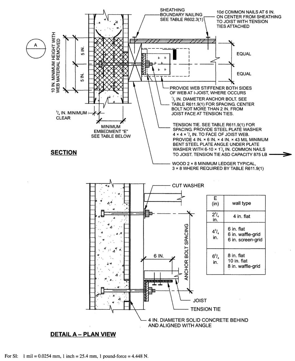
FIGURE R611.9(1)
WOOD FRAMED FLOOR TO SIDE OF CONCRETE WALL, FRAMING PERPENDICULAR
| ANCHOR BOLT SPACING (inches) | TENSION TIE SPACING (inches) | BASIC WIND SPEED (mph) | |||||
|---|---|---|---|---|---|---|---|
| 85B | 90B | 100B | 110B | 120B | 130B | ||
| 85C | 90C | 100C | 110C | ||||
| 85D | 90D | 100D | |||||
| For SI: 1 inch = 25.4 mm; 1 mile per hour = 0.447 m/s. | |||||||
| a. This table is for use with the detail in Figure R611.9(1). Use of this detail is permitted where a cell is not shaded and prohibited where shaded. | |||||||
| b. Wall design per other provisions of Section R611 is required. | |||||||
| c. Letter “A” indicates that a minimum nominal 3 x 8 ledger is required. | |||||||
| 12 | 12 | ||||||
| 12 | 24 | ||||||
| 12 | 36 | ||||||
| 12 | 48 | ||||||
| 16 | 16 | A | A | ||||
| 16 | 32 | ||||||
| 16 | 48 | ||||||
| 19.2 | 19.2 | A | A | A | A | A | |
| 19.2 | 38.4 | A | A | A | |||
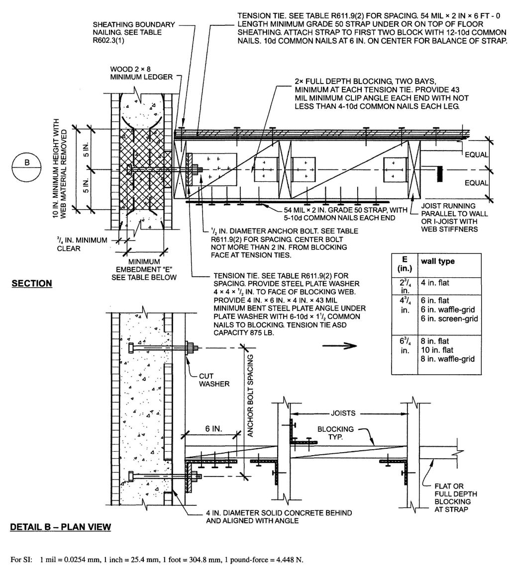
FIGURE R611.9(2)
WOOD FRAMED FLOOR TO SIDE OF CONCRETE WALL FRAMING PARALLEL
| ANCHOR BOLT SPACING (inches) | TENSION TIE SPACING (inches) | BASIC WIND SPEED (mph) | |||||
|---|---|---|---|---|---|---|---|
| 85B | 90B | 100B | 110B | 120B | 130B | ||
| 85C | 90C | 100C | 110C | ||||
| 85D | 90D | 100D | |||||
| For SI: 1 inch = 25.4 mm; 1 mph = 0.447 m/s. | |||||||
| a. This table is for use with the detail in Figure R611.9(2). Use of this detail is permitted where a cell is not shaded and prohibited where shaded. | |||||||
| b. Wall design per other provisions of Section R611 is required. | |||||||
| 12 | 12 | ||||||
| 12 | 24 | ||||||
| 12 | 36 | ||||||
| 12 | 48 | ||||||
| 16 | 16 | ||||||
| 16 | 32 | ||||||
| 16 | 48 | ||||||
| 19.2 | 19.2 | ||||||
| 19.2 | 38.4 | ||||||
| 24 | 24 | ||||||
| 24 | 48 | ||||||
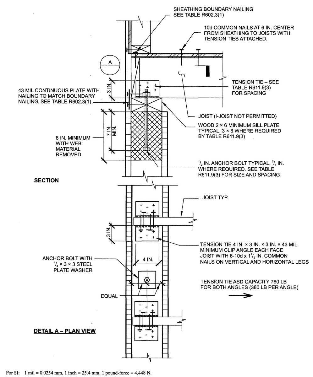
FIGURE R611.9(3)
WOOD FRAMED FLOOR TO TOP OF CONCRETE WALL FRAMING PERPENDICULAR
| ANCHOR BOLT SPACING (inches) | TENSION TIE SPACING (inches) | BASIC WIND SPEED (mph) AND WIND EXPOSURE CATEGORY | |||||
|---|---|---|---|---|---|---|---|
| 85B | 90B | 100B | 110B | 120B | 130B | ||
| 85C | 90C | 100C | 110C | ||||
| 85D | 90D | 100D | |||||
| For SI: 1 inch = 25.4 mm; 1 mile per hour = 0.447 m/s. | |||||||
| a. This table is for use with the detail in Figure R611.9(3). Use of this detail is permitted where cell is not shaded, prohibited where shaded. | |||||||
| b. Wall design per other provisions in Section R611 is required. | |||||||
| c. For wind design, minimum 4-inch nominal wall is permitted in unshaded cells with no number. | |||||||
| d. Number 6 indicates minimum permitted nominal wall thickness in inches necessary to develop required strength (capacity) of connection. As a minimum, this nominal thickness shall occur in the portion of the wall indicated by the cross-hatching in Figure R611.9(3). For the remainder of the wall, see Note b. | |||||||
| e. Letter “A” indicates that a minimum nominal 3 × 6 sill plate is required. Letter “B” indicates that a 5/8 inch (16 mm) diameter anchor bolt and a minimal nominal 3 × 6 sill plate are required. | |||||||
| 12 | 12 | ||||||
| 12 | 24 | ||||||
| 12 | 36 | ||||||
| 12 | 48 | ||||||
| 16 | 16 | 6 A |
6 B | ||||
| 16 | 32 | 6 A |
6 B | ||||
| 16 | 48 | ||||||
| 19.2 | 19.2 | 6 A |
6 A |
6 B | |||
| 19.2 | 38.4 | 6 A |
6 A |
||||
| 24 | 24 | 6 A |
6 B |
6 A |
|||
| 24 | 48 | 6 A |
|||||
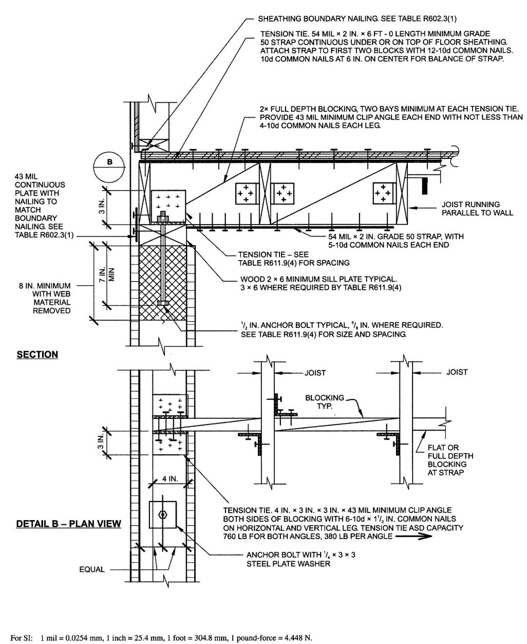
FIGURE R611.9(4)
WOOD FRAMED FLOOR TO TOP OF CONCRETE WALL FRAMING PARALLEL
| ANCHOR BOLT SPACING (inches) | TENSION TIE SPACING (inches) | BASIC WIND SPEED (mph) AND WIND EXPOSURE CATEGORY | |||||
|---|---|---|---|---|---|---|---|
| 85B | 90B | 100B | 110B | 120B | 130B | ||
| 85C | 90C | 100C | 110C | ||||
| 85D | 90D | 100D | |||||
| For SI: 1 inch = 25.4 mm; 1 mile per hour = 0.447 m/s. | |||||||
| a. This table is for use with the detail in Figure R611.9(4). Use of this detail is permitted where a cell is not shaded, prohibited where shaded. | |||||||
| b. Wall design per other provisions of Section R611 is required. | |||||||
| c. For wind design, minimum 4-inch nominal wall is permitted in unshaded cells with no number. | |||||||
| d. Number 6 indicates minimum permitted nominal wall thickness in inches necessary to develop required strength (capacity) of connection. As a minimum, this nominal thickness shall occur in the portion of the wall indicated by the cross-hatching in Figure R611.9(4). For the remainder of the wall, see Note b. | |||||||
| e. Letter “A” indicates that a minimum nominal 3 × 6 sill plate is required. Letter “B” indicates that a 5/8 inch diameter anchor bolt and a minimal nominal 3 × 6 sill plate are required. | |||||||
| 12 | |||||||
| 12 | 24 | ||||||
| 12 | 36 | ||||||
| 12 | 48 | ||||||
| 16 | 16 | 6 A |
6 A |
||||
| 16 | 32 | 6 A |
6 B |
||||
| 16 | 48 | ||||||
| 19.2 | 19.2 | 6 A |
6 A |
6 B |
|||
| 19.2 | 38.4 | 6 |
6 |
||||
| 24 | 24 | 6 A |
6 B |
6 B |
|||
| 24 | 48 | 6 A |
|||||
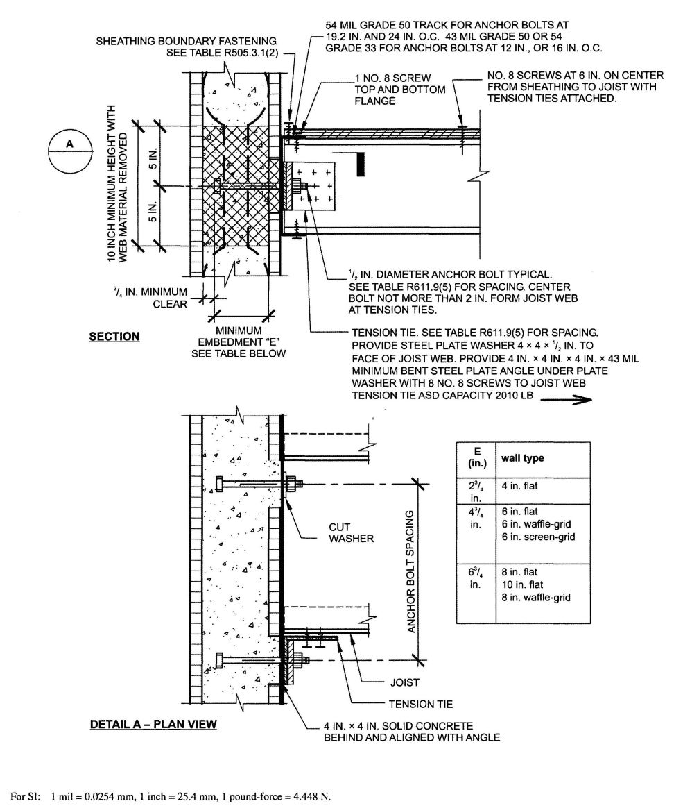
FIGURE R611.9(5)
COLD-FORMED STEEL FLOOR TO SIDE OF CONCRETE WALL, FRAMING PERPENDICULAR
| ANCHOR BOLT SPACING (inches) | TENSION TIE SPACING (inches) | BASIC WIND SPEED (mph) AND WIND EXPOSURE CATEGORY | |||||
|---|---|---|---|---|---|---|---|
| 85B | 90B | 100B | 110B | 120B | 130B | ||
| 85C | 90C | 100C | 110C | ||||
| 85D | 90D | 100D | |||||
| For SI: 1 inch = 25.4 mm; 1 mile per hour = 0.4470 m/s. | |||||||
| a. This table is for use with the detail in Figure R611.9(5). Use of this detail is permitted where a cell is not shaded. | |||||||
| b. Wall design per other provisions of Section R611 is required. | |||||||
| c. For wind design, minimum 4-inch nominal wall is permitted in unshaded cells with no number. | |||||||
| d. Number 6 indicates minimum permitted nominal wall thickness in inches necessary to develop required strength (capacity) of connection. As a minimum, this nominal thickness shall occur in the portion of the wall indicated by the cross-hatching in Figure R611.9(5). For the remainder of the wall, see Note b. | |||||||
| 12 | 12 | ||||||
| 12 | 24 | ||||||
| 12 | 36 | 6 | |||||
| 12 | 48 | 6 | 6 | ||||
| 16 | 16 | ||||||
| 16 | 32 | ||||||
| 16 | 48 | 6 | 6 | ||||
| 19.2 | 19.2 | ||||||
| 19.2 | 38.4 | 6 | |||||
| 24 | 24 | ||||||
| 24 | 48 | 6 | 6 | ||||
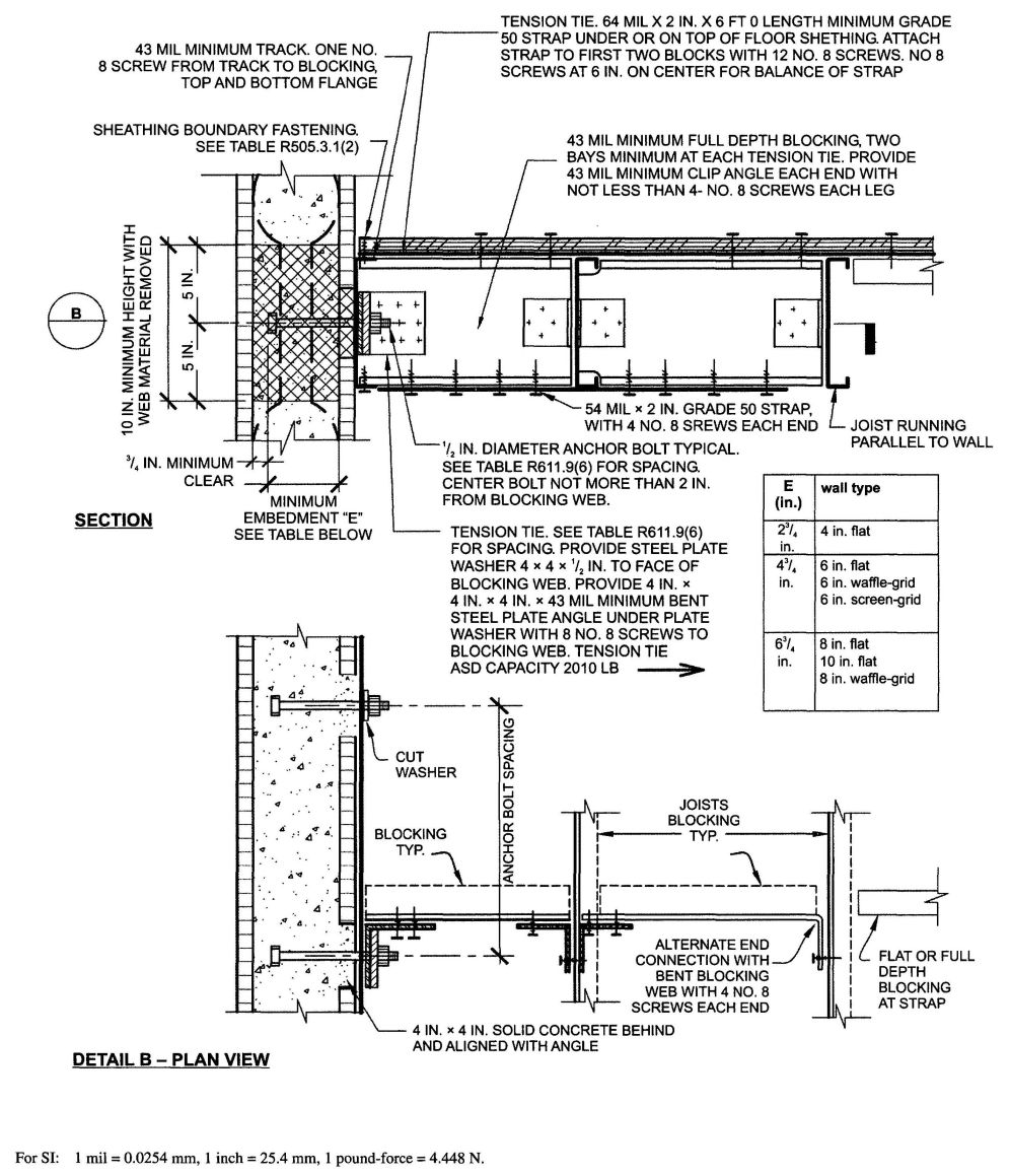
FIGURE R611.9(6)
COLD-FORMED STEEL FLOOR TO SIDE OF CONCRETE WALL, FRAMING PARALLEL
| ANCHOR BOLT SPACING (inches) | TENSION TIE SPACING (inches) | BASIC WIND SPEED (mph) AND WIND EXPOSURE CATEGORY | |||||
|---|---|---|---|---|---|---|---|
| 85B | 90B | 100B | 110B | 120B | 130B | ||
| 85C | 90C | 100C | 110C | ||||
| 85D | 90D | 100D | |||||
| For SI: 1 inch=25.4 mm; 1 mile per hour= 0.447 m/s. | |||||||
| a. This table is for use with the detail in Figure R611.9(6). Use of this detail is permitted where a cell is not shaded. | |||||||
| b. Wall design per other provisions of Section R611 is required. | |||||||
| c. For wind design, minimum 4-inch nominal wall is permitted in unshaded cells with no number. | |||||||
| d. Number 6 indicates minimum permitted nominal wall thickness in inches necessary to develop required strength (capacity) of connection. As a minimum, this nominal thickness shall occur in the portion of the wall indicated by the cross-hatching in Figure R611.9(6). For the remainder of the wall, see Note b. | |||||||
| 12 | 12 | ||||||
| 12 | 24 | ||||||
| 12 | 36 | 6 | |||||
| 12 | 48 | 6 | 6 | ||||
| 16 | 16 | ||||||
| 16 | 32 | ||||||
| 16 | 48 | 6 | 6 | ||||
| 19.2 | 19.2 | ||||||
| 19.2 | 38.4 | 6 | |||||
| 24 | 24 | ||||||
| 24 | 48 | 6 | 6 | ||||
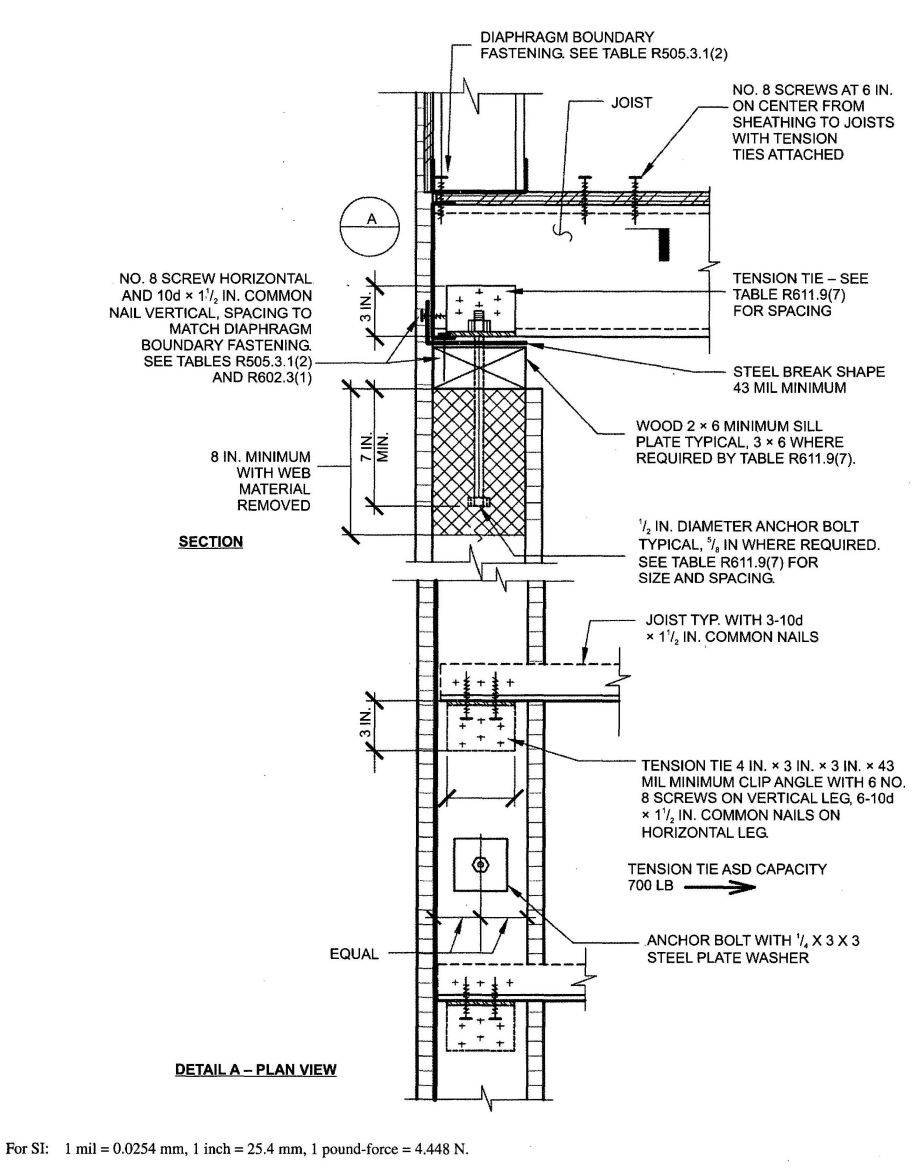
FIGURE R611.9(7)
COLD-FORMED STEEL FLOOR TO TOP OF CONCRETE WALL FRAMING PERPENDICULAR
| ANCHOR BOLT SPACING (inches) | TENSION TIE SPACING (inches) | BASIC WIND SPEED (mph) AND WIND EXPOSURE CATEGORY | |||||
|---|---|---|---|---|---|---|---|
| 85B | 90B | 100B | 110B | 120B | 130B | ||
| 858C | 90C | 100C | 110C | ||||
| 85D | 90D | 100D | |||||
| For SI: 1 inch=25.4 mm; 1 mph=0.447 m/s. | |||||||
| a. This table is for use with the detail in Figure R611.9(7). Use of this detail is permitted where a cell is not shaded, prohibited where shaded. | |||||||
| b. Wall design per other provisions of Section R611 is required. | |||||||
| c. For wind design, minimum 4-inch nominal wall is permitted in unshaded cells with no number. | |||||||
| d. Number 6 and 8 indicate minimum permitted nominal wall thickness in inches necessary to develop required strength (capacity) of connection. As a minimum, this nominal thickness shall occur in the portion of the wall indicated by the cross-hatching in Figure R611.9(7). For the remainder of the wall, see Note b. | |||||||
| e. Letter “A” indicates that a minimum nominal 3 × 6 sill plate is required. Letter “B” indicates that a 5/8 inch diameter anchor bolt and a minimum nominal 3 × 6 sill plate are required. | |||||||
| 12 | 12 | ||||||
| 12 | 24 | ||||||
| 16 | 16 | 6 A |
6 B |
||||
| 16 | 32 | 6 A |
6 B |
||||
| 19.2 | 19.2 | 6 A |
8 B |
8 B |
|||
| 19.2 | 38.4 | 6 A |
8 B |
8 B |
|||
| 24 | 24 | 6 A |
8 B |
8 B |
|||
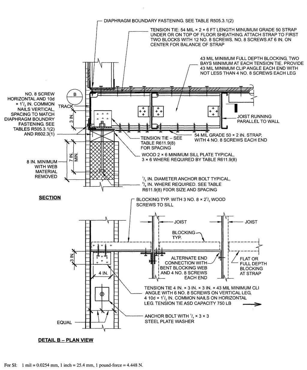
FIGURE R611.9(8)
COLD-FORMED STEEL FLOOR TO TOP OF CONCRETE WALL, FRAMING PARALLEL
| ANCHOR BOLT SPACING (inches) | TENSION TIE SPACING (inches) | BASIC WIND SPEED (mph) AND WIND EXPOSURE CATEGORY | |||||
|---|---|---|---|---|---|---|---|
| 85B | 90B | 100B | 110B | 120B | 130B | ||
| 85C | 90C | 100C | 110C | ||||
| 85D | 90D | 100D | |||||
| For SI: 1 inch= 25.4 mm; 1 mph= 0.447 m/s. | |||||||
| a. This table is for use with the detail in Figure R611.9(8). Use of this detail is permitted where a cell is not shaded, prohibited where shaded. | |||||||
| b. Wall design per other provisions of Section R611 is required. | |||||||
| c. For wind design, minimum 4-inch nominal wall is permitted in unshaded cells with no number. | |||||||
| d. Number 6 and 8 indicate minimum permitted nominal wall thickness in inches necessary to develop required strength (capacity) of connection. As a minimum, this nominal thickness shall occur in the portion of the wall indicated by the cross-hatching in Figure R611.9(8). For the remainder of the wall, see Note b. | |||||||
| e. Letter “A” indicates that a minimum nominal 3 × 6 sill plate is required. Letter “B” indicates that a 5/8 inch diameter anchor bolt and a minimum nominal 3 × 6 sill plate are required. | |||||||
| 12 | 12 | ||||||
| 12 | 24 | ||||||
| 16 | 16 | 6 A |
6 B |
||||
| 16 | 32 | 6 A |
6 B |
||||
| 19.2 | 19.2 | 6 A |
8 B |
8 B |
|||
| 19.2 | 38.4 | 6 A |
8 B |
8 B |
|||
| 24 | 24 | 6 A |
8 B |
8 B |
|||
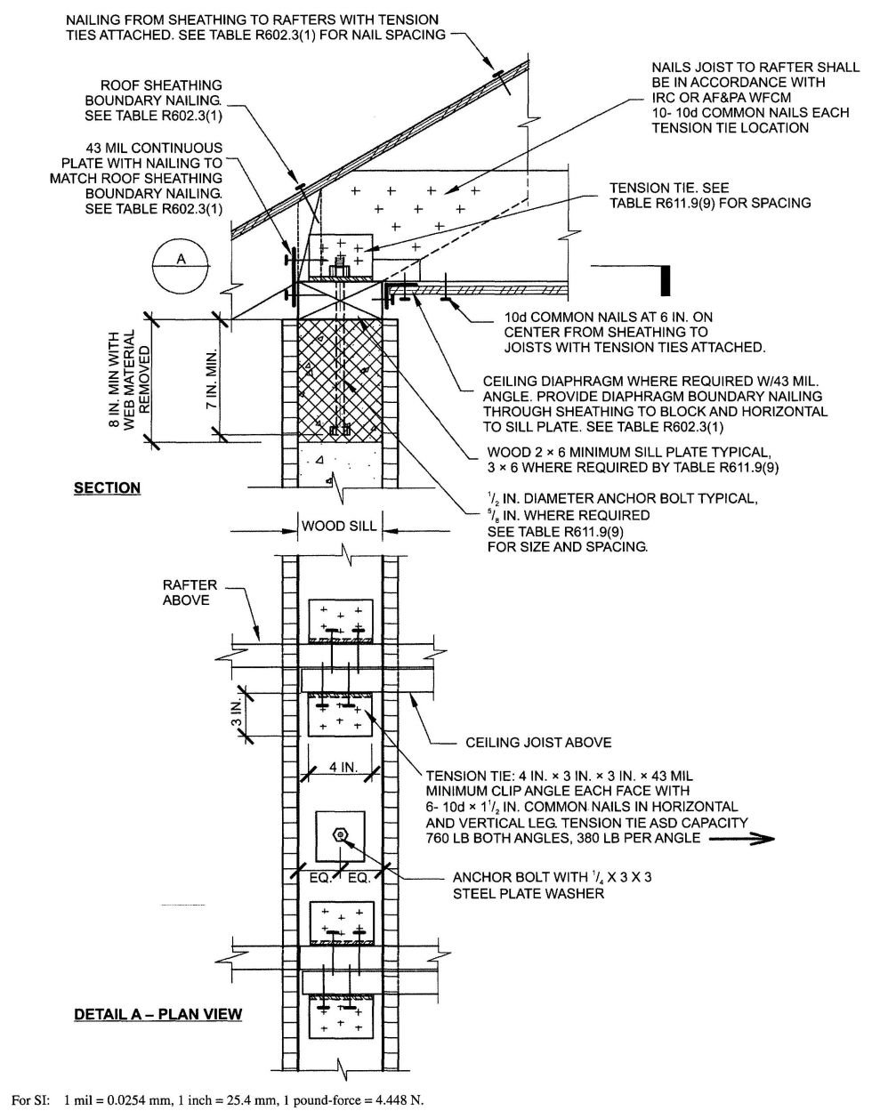
FIGURE R611.9(9)
WOOD FRAMED ROOF TO TOP OF CONCRETE WALL, FRAMING PERPENDICULAR
| ANCHOR BOLT SPACING (inches) | TENSION TIE SPACING (inches) | BASIC WIND SPEED (mph) AND WIND EXPOSURE CATEGORY | |||||
|---|---|---|---|---|---|---|---|
| 85B | 90B | 100B | 110B | 120B | 130B | ||
| 85C | 90C | 100C | 110C | ||||
| 85D | 90D | 100D | |||||
| For SI: 1 inch = 25.4 mm; 1 mph = 0.447 m/s. | |||||||
| a. This table is for use with the detail in Figure R611.9(9). Use of this detail is permitted where cell a is not shaded, prohibited where shaded. | |||||||
| b. Wall design per other provisions of Section R611 is required. | |||||||
| c. For wind design, minimum 4-inch nominal wall is permitted in unshaded cells with no number. | |||||||
| d. Number 6 indicates minimum permitted nominal wall thickness in inches necessary to develop required strength (capacity) of connection. As a minimum, this nominal thickness shall occur in the portion of the wall indicated by the cross-hatching in Figure R611.9(9). For the remainder of the wall, see Note b. | |||||||
| e. Letter “A” indicates that a minimum nominal 3 × 6 sill plate is required. Letter “B” indicates that a 5/8 inch diameter anchor bolt and minimum nominal 3 × 6 sill plate are required. | |||||||
| 12 | 12 | ||||||
| 12 | 24 | ||||||
| 12 | 36 | ||||||
| 12 | 48 | ||||||
| 16 | 16 | 6 | |||||
| 16 | 32 | 6 | |||||
| 16 | 48 | ||||||
| 19.2 | 19.2 | 6 | 6 A |
||||
| 19.2 | 38.4 | 6 | |||||
| 24 | 24 | 6 A |
6 A |
6 B |
|||
| 24 | 48 | ||||||
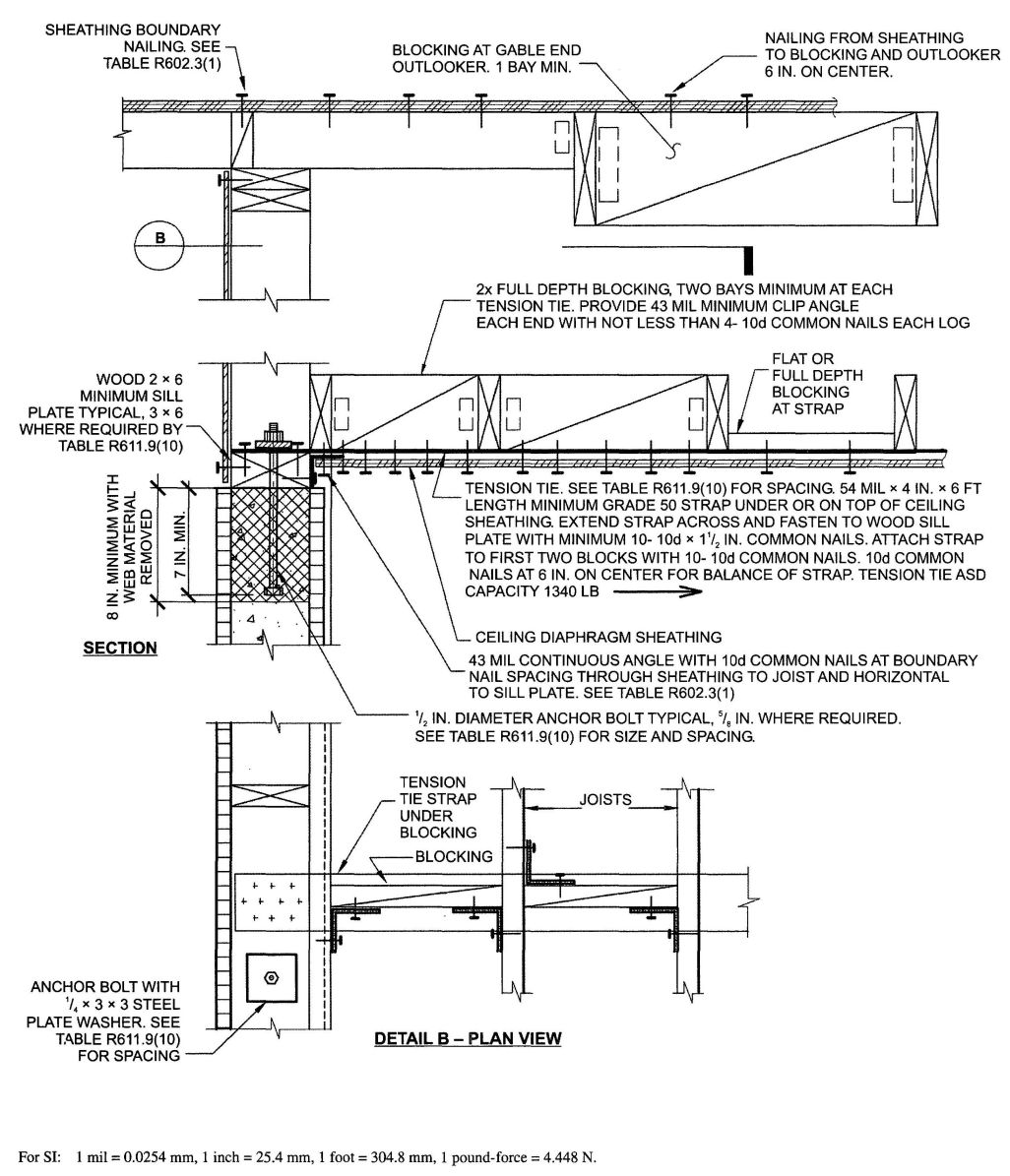
FIGURE R611.9(10)
WOOD FRAMED ROOF TO TOP OF CONCRETE WALL FRAMING PARALLEL
| ANCHOR BOLT SPACING(inches) | TENSION TIE SPACING(inches) | BASIC WIND SPEED (mph) AND WIND EXPOSURE CATEGORY | |||||
|---|---|---|---|---|---|---|---|
| 85B | 90B | 100B | 110B | 120B | 130B | ||
| 85C | 90C | 100C | 110C | ||||
| 85D | 90D | 100D | |||||
| For SI: 1 inch=25.4 mm; I mph=0.447 m/s. | |||||||
| a. This table is for use with the detail in Figure R611.9(10). Use of this detail is permitted where a cell is not shaded. | |||||||
| b. Wall design per other provisions of Section R611 is required. | |||||||
| c. For wind design, minimum 4-inch nominal wall is permitted in cells with no number. | |||||||
| d. Number 6 indicates minimum permitted nominal wall thickness in inches necessary to develop required strength (capacity) of connection. As a minimum, this nominal thickness shall occur in the portion of the wall indicated by the cross-hatching in Figure R611.9(10). For the remainder of the wall, see Note b. | |||||||
| e. Letter “A” indicates that a minimum nominal 3 × 6 sill plate is required. Letter “B” indicates that a 5/8 inch diameter anchor bolt and a minimum nominal 3 × 6 sill plate are required. | |||||||
| 12 | 12 | ||||||
| 12 | 24 | ||||||
| 12 | 36 | ||||||
| 12 | 48 | ||||||
| 16 | 16 | 6 | 6 | ||||
| 16 | 32 | 6 | 6 | ||||
| 16 | 48 | 6 | 6 | ||||
| 19.2 | 19.2 | 6 | 6 | 6 A |
|||
| 19.2 | 38.4 | 6 | 6 | 6 A |
|||
| 24 | 24 | 6 | 6 A |
6 A |
6 B |
||
| 24 | 48 | 6 | 6 A |
6 B |
6 B |
||
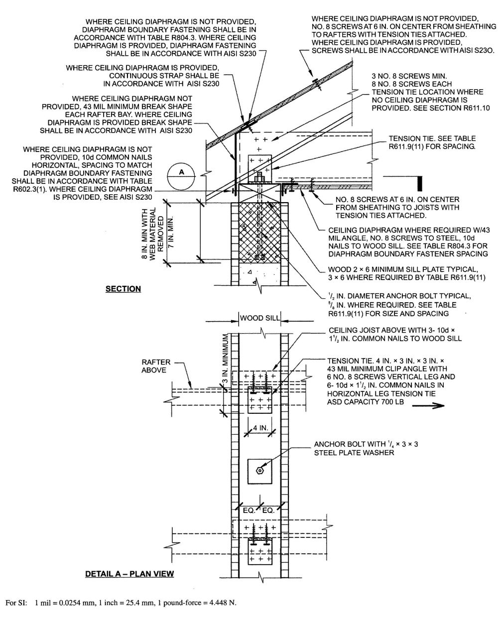
FIGURE R611.9(11)
COLD-FORMED STEEL ROOF TO TOP OF CONCRETE WALL, FRAMING PERPENDICULAR
| ANCHOR BOLT SPACING (inches) | TENSION TIE SPACING (inches) | BASIC WIND SPEED (mph) AND WIND EXPOSURE CATEGORY | |||||
|---|---|---|---|---|---|---|---|
| 85B | 90B | 100B | 110B | 120B | 130B | ||
| 85C | 90C | 100C | 110C | ||||
| 85D | 90D | 100D | |||||
| For SI: 1 inch = 25.4 mm; 1 mile per hour = 0.447 m/s. | |||||||
| a. This table is for use with the detail in Figure R611.9(11). Use of this detail is permitted where a cell is not shaded, prohibited where shaded. | |||||||
| b. Wall design per other provisions of Section R611 is required. | |||||||
| c. For wind design, minimum 4-inch nominal wall is permitted in unshaded cells with no number. | |||||||
| d. Numbers 6 and 8 indicate minimum permitted nominal wall thickness in inches necessary to develop required strength (capacity) of connection. As a minimum, this nominal thickness shall occur in the portion of the wall indicated by the cross-hatching in Figure R611.9(11). For the remainder of the wall, see Note b. | |||||||
| e. Letter “B” indicates that a 5/8 inch diameter anchor bolt and a minimum nominal 3 × 6 sill plate are required. | |||||||
| 12 | 12 | ||||||
| 12 | 24 | ||||||
| 16 | 16 | 6 | 6 | ||||
| 16 | 32 | 6 | 6 | ||||
| 19.2 | 19.2 | 6 | 6 | 8 B |
|||
| 19.2 | 38.4 | 6 | 6 | 8 B |
|||
| 24 | 24 | 6 | 6 | 8 B |
|||
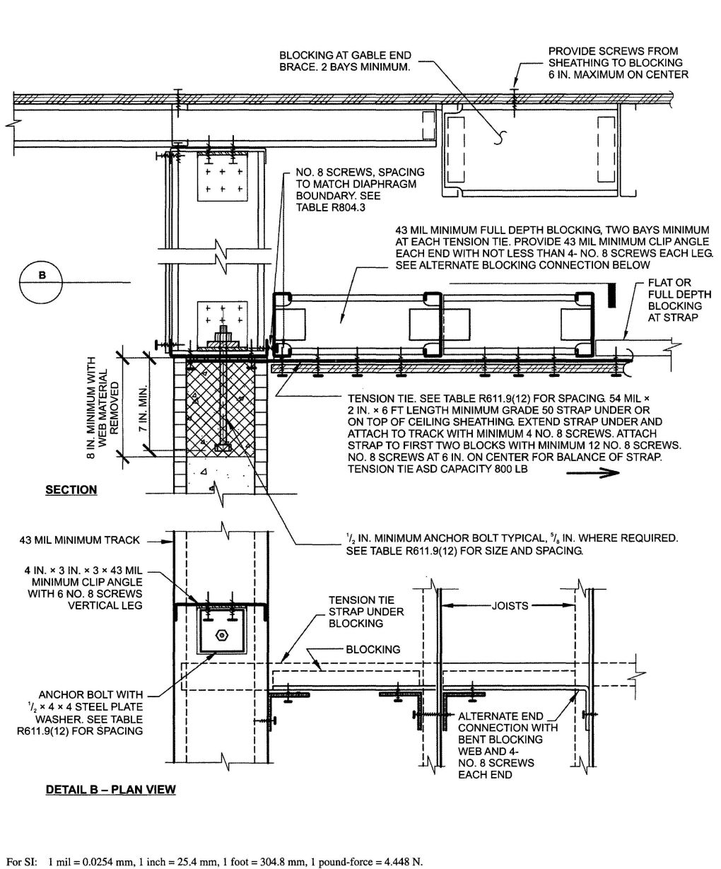
FIGURE R611.9(12)
COLD-FORMED STEEL ROOF TO TOP OF CONCRETE WALL, FRAMING PARALLEL
| ANCHOR BOLT SPACING (inches) | TENSION TIE SPACING (inches) | BASIC WIND SPEED (mph) AND WIND EXPOSURE CATEGORY | |||||
|---|---|---|---|---|---|---|---|
| 85B | 90B | 100B | 110B | 120B | 130B | ||
| 85C | 90C | 100C | 110C | ||||
| 85D | 90D | 100D | |||||
| For SI: 1 inch = 25.4 mm; 1 mile per hour = 0.447 m/s. | |||||||
| a. This table is for use with the detail in Figure R611.9(12). Use of this detail is permitted where a cell is not shaded. | |||||||
| b. Wall design per other provisions of Section R611 is required. | |||||||
| c. For wind design, minimum 4-inch nominal wall is permitted in cells with no number. | |||||||
| d. Numbers 6 and 8 indicate minimum permitted nominal wall thickness in inches necessary to develop required strength (capacity) of connection. As a minimum, this nominal thickness shall occur in the portion of the wall indicated by the cross-hatching in Figure R611.9(12). For the remainder of the wall, see Note b. | |||||||
| e. Letter “B” indicates that a 5/8 inch diameter anchor bolt is required. | |||||||
| 12 | 12 | ||||||
| 12 | 24 | ||||||
| 16 | 16 | ||||||
| 16 | 32 | ||||||
| 19.2 | 19.2 | 6 | 6 | ||||
| 19.2 | 38.4 | 6 | 6 | ||||
| 24 | 24 | 6 | 6 | 8 B |
8 B |
||
R612.1 General. This section prescribes performance and construction requirements for exterior window and door installed in wall. Windows and doors shall be installed and flashed in accordance with the fenestration manufacturer's written installation instructions. Window and door openings shall be flashed in accordance with Section R703.8. Written installation instructions shall be provided by the fenestration manufacturer for each window or door.
R612.2 Window sills. In dwelling units, where the opening of an operable window is located more than 72 inches (1829 mm) above the finished grade or surface below, the lowest part of the clear opening of the window shall be a minimum of 24 inches (610 mm) above the finished floor of the room in which the window is located. Operable sections of windows shall not permit openings that allow passage of a 4 inch (102 mm) diameter sphere where such openings are located within 24 inches (610 mm) of the finished floor.
Exceptions:
- Windows whose openings will not allow a 4-inch-diameter (102 mm) sphere to pass through the opening when the opening is in its largest opened position.
- Openings that are provided with window fall prevention devices that comply with Section R612.3.
- Openings that are provided with fall prevention devices that comply with ASTM F 2090.
- Windows that are provided with opening limiting devices that comply with Section R612.4.
R612.3 Window fall prevention devices. Window fall prevention devices and window guards, where provided, shall comply with the requirements of ASTM F 2090.
R612.4 Window opening limiting devices. When required elsewhere in this code, window opening limiting devices shall comply with the provisions of this section.
R612.4.1 General requirements. Window opening limiting devices shall be self acting and shall be positioned to prohibit the free passage of a 4-in. (102-mm) diameter rigid sphere through the window opening when the window opening limiting device is installed in accordance with the manufacturer's instructions.
R612.4.2 Operation for emergency escape. Window opening limiting devices shall be designed with release mechanisms to allow for emergency escape through the window opening without the need for keys, tools or special knowledge. Window opening limiting devices shall comply with all of the following:
R612.5 Performance. Exterior windows and doors shall be designed to resist the design wind loads specified in Table R301.2(2) adjusted for height and exposure per Table R301.2(3).
R612.6 Testing and labeling. Exterior windows and sliding doors shall be tested by an approved independent laboratory, and bear a label identifying manufacturer, performance characteristics and approved inspection agency to indicate compliance with AAMA/WDMA/CSA 101/I.S.2/A440. Exterior side-hinged doors shall be tested and labeled as conforming to AAMA/WDMA/CSA 101/I.S.2/A440 or comply with Section R612.8.
Exception: Decorative glazed openings.
R612.6.1 Comparative analysis. Structural wind load design pressures for window and door units smaller than the size tested in accordance with Section R612.6 shall be permitted to be higher than the design value of the tested unit provided such higher pressures are determined by accepted engineering analysis. All components of the small unit shall be the same as those of the tested unit. Where such calculated design pressures are used, they shall be validated by an additional test of the window or door unit having the highest allowable design pressure.
R612.7 Vehicular access doors. Vehicular access doors shall be tested in accordance with either ASTM E 330 or ANSI/DASMA 108, and shall meet the acceptance criteria of ANSI/DASMA 108.
R612.8 Other exterior window and door assemblies. Exterior windows and door assemblies not included within the scope of Section R612.6 or Section R612.7 shall be tested in accordance with ASTM E 330. Glass in assemblies covered by this exception shall comply with Section R308.5.
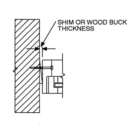
FIGURE R612.8(1)
THROUGH THE FRAME
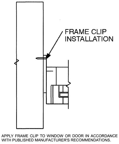
FIGURE R612.8(2)
FRAME CLIP
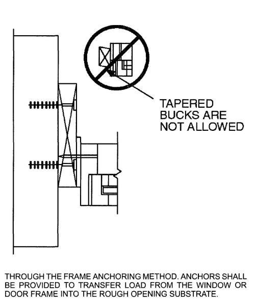
FIGURE R612.8(3)
FRAME CLIP
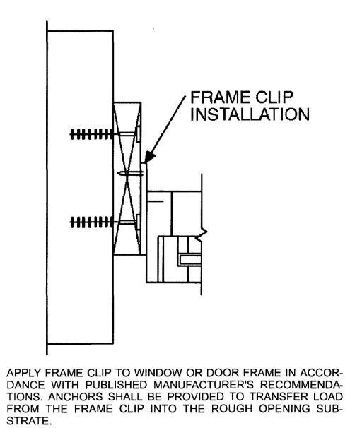
FIGURE R612.8(4)
THROUGH THE FRAME
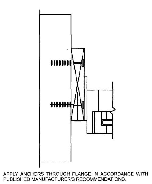
FIGURE R612.8(5)
THROUGH THE FLANGE
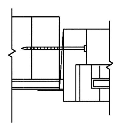
FIGURE R612.8(6)
THROUGH THE FLANGE
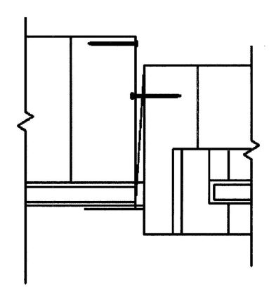
FIGURE R612.8(7)
FRAME CLIP
R612.9 Wind-borne debris protection. Protection of exterior windows and glass doors in buildings located in wind-borne debris regions shall be in accordance with Section R301.2.1.2.
R612.9.1 Fenestration testing and labeling. Fenestration shall be tested by an approved independent laboratory, listed by an approved entity, and bear a label identifying manufacturer, performance characteristics, and approved inspection agency to indicate compliance with the requirements of the following specification:
R612.10 Anchorage methods. The methods cited in this section apply only to anchorage of window and glass door assemblies to the main force-resisting system.
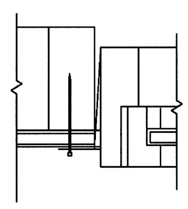
FIGURE R612.8(8)
THROUGH THE FLANGE
R612.10.1 Anchoring requirements. Window and glass door assemblies shall be anchored in accordance with the published manufacturer's recommendations to achieve the design pressure specified. Substitute anchoring systems used for substrates not specified by the fenestration manufacturer shall provide equal or greater anchoring performance as demonstrated by accepted engineering practice.
R612.10.2 Anchorage details. Products shall be anchored in accordance with the minimum requirements illustrated in Figures R612.8(1), R612.8(2), R612.8(3), R612.8(4), R612.8(5), R612.8(6), R612.8(7) and R612.8(8).
R612.10.2.1 Masonry, concrete or other structural substrate. Where the wood shim or buck thickness is less than 1½ inches (38 mm), window and glass door assemblies shall be anchored through the jamb, or by jamb clip and anchors shall be embedded directly into the masonry, concrete or other substantial substrate material. Anchors shall adequately transfer load from the window or door frame into the rough opening substrate [see Figures R612.8(1) and R612.8(2).]
Where the wood shim or buck thickness is 1½ inches (38 mm) or more, the buck is securely fastened to the masonry, concrete or other substantial substrate, and the buck extends beyond the interior face of the window or door frame, window and glass door assemblies shall be anchored through the jamb, or by jamb clip, or through the flange to the secured wood buck. Anchors shall be embedded into the secured wood buck to adequately transfer load from the window or door frame assembly [Figures R612.8(3), R612.8(4) and R612.8(5)].
R612.10.2.2 Wood or other approved framing material. Where the framing material is wood or other approved framing material, window and glass door assemblies shall be anchored through the frame, or by frame clip, or through the flange. Anchors shall be embedded into the frame construction to adequately transfer load [Figures R612.8(6), R612.8(7) and R612.8(8)].
R612.11 Mullions. Mullions shall be tested by an approved testing laboratory in accordance with AAMA 450, or be engineered in accordance with accepted engineering practice. Mullions tested as stand-alone units or qualified by engineering shall use performance criteria cited in Sections R612.11.1, R612.11.2 and R612.11.3. Mullions qualified by an actual test of an entire assembly shall comply with Sections R612.11.1 and R612.11.3.
R612.11.1 Load transfer. Mullions shall be designed to transfer the design pressure loads applied by the window and door assemblies to the rough opening substrate.
R612.11.2 Deflection. Mullions shall be capable of resisting the design pressure loads applied by the window and door assemblies to be supported without deflecting more than L/175, where L is the span of the mullion in inches.
R612.11.3 Structural safety factor. Mullions shall be capable of resisting a load of 1.5 times the design pressure loads applied by the window and door assemblies to be supported without exceeding the appropriate material stress levels. If tested by an approved laboratory, the 1.5 times the design pressure load shall be sustained for 10 seconds, and the permanent deformation shall not exceed 0.4 percent of the mullion span after the 1.5 times design pressure load is removed.
R613.1 General. Structural insulated panel (SIP) walls shall be designed in accordance with the provisions of this section. The provisions of this section used to design structural insulated panel walls, project drawings, typical details and specifications shall not exempt construction documents from the requirement to be stamped by a California licensed architect or engineer. Notwithstanding other sections of law, the law establishing these provisions is found in Business and Professions Code Sections 5537.1 and 6737.1.
R613.2 Applicability limits. The provisions of this section shall control the construction of exterior structural insulated panel walls and interior load-bearing structural insulated panel walls for buildings not greater than 60 feet (18 288 mm) in length perpendicular to the joist or truss span, not greater than 40 feet (12 192 mm) in width parallel to the joist or truss span and not greater than two stories in height with each wall not greater than 10 feet (3048 mm) high. All exterior walls installed in accordance with the provisions of this section shall be considered as load-bearing walls. Structural insulated panel walls constructed in accordance with the provisions of this section shall be limited to sites subjected to a maximum design wind speed of 130 miles per hour (58 m/s), Exposure A, B or C, and a maximum ground snow load of 70 pounds per foot (3.35 kPa), and Seismic Design Categories A, B, and C.
R613.3 Materials. SIPs shall comply with the following criteria:
R613.3.1 Core. The core material shall be composed of foam plastic insulation meeting one of the following requirements:
All cores shall meet the requirements of Section R316.
R613.3.2 Facing. Facing materials for SIPs shall be wood structural panels conforming to DOC PS 1 or DOC PS 2, each having a minimum nominal thickness of 7/16 inch (11 mm) and shall meet the additional minimum properties specified in Table R613.3.2. Facing shall be identified by a grade mark or certificate of inspection issued by an approved agency.
R613.3.3 Adhesive. Adhesives used to structurally laminate the foam plastic insulation core material to the structural wood factors shall conform to ASTM D 2559 or approved alternative specifically intended for use as an adhesive used in the lamination of structural insulated panels. Each container of adhesive shall bear a label with the adhesive manufacturer’s name, adhesive name and type and the name of the quality assurance agency.
R613.3.4 Lumber. The minimum lumber framing material used for SIPs prescribed in this document is NLGA graded No. 2 Spruce-pine-fir. Substitution of other wood spe
| PHYSICAL PROPERTY | POLYURETHANE |
|---|---|
| For SI: 1 pound per cubic foot = 16.02 kg/m3, 1 pound per square inch= 6.895 kPa, °C = [(°F) - 32]1.8. | |
| Density, core nominal. (ASTM D 1622) | 2.2 lb/ft3 |
| Compressive resistance at yield or 10% deformation, whichever occurs first. (ASTM D 1621) | 19 psi (perpendicular to rise) |
| Flexural strength, min. (ASTM C 203) | 30 psi |
| Tensile strength, min. (ASTM D 1623) | 35 psi |
| Shear strength, min. (ASTM C 273) | 25 psi |
| Substrate adhesion, min. (ASTM D 1623) | 22 psi |
| Water vapor permeance of 1.00-in. thickness, max. (ASTM E 96) | 2.3 perm |
| Water absorption by total immersion, max. (ASTM C 272) | 4.3% (volume) |
| Dimensional stability (change in dimensions), max. [ASTM D2126 (7 days at 158°F/100% humidity and 7 days at -20°F)] | 2% |
| THICKNESS (inch) | PRODUCT | FLATWISE STIFFNESSb (lbf-in2/ft) | FLATWISE STRENGTHc (lbf-in/ft) | TENSIONc (lbf/ft) | DENSITYb,d (pcf) | |||
|---|---|---|---|---|---|---|---|---|
| Along | Across | Along | Across | Along | Across | |||
| For SI: 1 inch = 25.4 mm, 1 lbf-in2/ft = 9.415 * 10-6 kPa/m, 1 lbf-in/ft = 3.707 * 10-4 kN/m, 1 lbf/ft = 0.0146 N/mm, 1 pound per cubic foot = 16.018 kg/m3. | ||||||||
| a. Values listed in Table R613.3.2 are qualification test values and are not to be used for design purposes. | ||||||||
| b. Mean test value shall be in accordance with Section 7.6 of DOC PS 2. | ||||||||
| c. Characteristic test value (5th percent with 75% confidence). | ||||||||
| d. Density shall be based on oven-dry weight and oven-dry volume. | ||||||||
| 7/16 | Sheathing | 54,700 | 27,100 | 950 | 870 | 6,800 | 6,500 | 35 |
cies/grades that meet or exceed the mechanical properties and specific gravity of No. 2 Spruce-pine-fir shall be permitted.
R613.3.5 SIP screws. Screws used for the erection of SIPs as specified in Section R613.5 shall be fabricated from steel, shall be provided by the SIPs manufacturer and shall be sized to penetrate the wood member to which the assembly is being attached by a minimum of 1 inch (25 mm). The screws shall be corrosion resistant and have a minimum shank diameter of 0.188 inch (4.7 mm) and a minimum head diameter of 0.620 inch (15.5 mm).
R613.3.6 Nails. Nails specified in Section R613 shall be common or galvanized box unless otherwise stated.
R613.4 SIP wall panels. SIPs shall comply with Figure R613.4 and shall have minimum panel thickness in accordance with Tables R613.5(1) and R613.5(2) for above-grade walls. All SIPs shall be identified by grade mark or certificate of inspection issued by an approved agency.
R613.4.1. Labeling. All panels shall be identified by grade mark or certificate of inspection issued by an approved agency. Each (SIP) shall bear a stamp or label with the following minimum information:
R613.5 Wall construction. Exterior walls of SIP construction shall be designed and constructed in accordance with the provisions of this section and Tables R613.5(1) and R613.5(2) and Figures R613.5(1) through R613.5(5). SIP walls shall be fastened to other wood building components in accordance with Tables R602.3(1) through R602.3(4).
Framing shall be attached in accordance with Section R602.3(1) unless otherwise provided for in Section R613.
R613.5.1 Top plate connection. SIP walls shall be capped with a double to plate installed to provide overlapping at corner, intersections and splines in accordance with Figure R613.5.1. The double top plates shall be made up of a single 2 by top plate having a width equal to the width of the panel core, and shall be recessed into the SIP below. Over this top plate a cap plate shall be placed. The cap plate width shall match the SIP thickness and overlap the facers on both sides of the panel. End joints in top plates shall be offset at least 24 inches (610 mm).
R613.5.2 Bottom (sole) plate connection. SIP walls shall have full bearing on a sole plate having a width equal to the nominal width of the foam core. When SIP walls are supported directly on continuous foundations, the wall wood sill plate shall be anchored to the foundation in accordance with Figure R613.5.2 and Section R403.1.
R613.5.3 Wall bracing. SIP walls shall be braced in accordance with Section R602.10. SIP walls shall be considered continuous wood structural panel sheathing for purposes of computing required bracing. SIP walls shall meet the requirements of Section R602.10.4 except that SIPs corners shall be fabricated as shown in Figure R613.9. When SIP walls are used for wall bracing, the SIP bottom plate shall be attached to wood framing below in accordance with Table R602.3(1).
R613.6 Interior load-bearing walls. Interior load-bearing walls shall be constructed as specified for exterior walls.
R613.7 Drilling and notching. The maximum vertical chase penetration in SIPs shall have a maximum side dimension of 2 inches (51 mm) centered in the panel core. Vertical chases shall have a minimum spacing of 24-inches (610 mm) on center. Maximum of two horizontal chases shall be permitted in each wall panel, one at 14 inches (360 mm) from the bottom of the panel and one at mid-height of the wall panel. The maximum allowable penetration size in a wall panel shall be circular or rectangular with a maximum dimension of 12 inches (305 mm). Overcutting of holes in facing panels shall not be permitted.
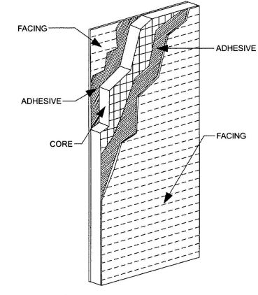
FIGURE R613.4
SIP WALL PANEL
| WIND SPEED (3-second gust) | SNOW LOAD (psf) | BUILDING WIDTH (feet) | |||||||||||||||
|---|---|---|---|---|---|---|---|---|---|---|---|---|---|---|---|---|---|
| 24 | 28 | 32 | 36 | 40 | |||||||||||||
| Exp. A/B | Exp. C | Wall Height (ft) | Wall Height (ft) | Wall Height (ft) | Wall Height (ft) | Wall Height (ft) | |||||||||||
| 8 | 9 | 10 | 8 | 9 | 10 | 8 | 9 | 10 | 8 | 9 | 10 | 8 | 9 | 10 | |||
| For SI: 1 inch = 25.4 mm; 1 foot = 304.8 mm; 1 pound per square foot = 0.0479kPa. | |||||||||||||||||
| Maximum deflection criterion:L/240. | |||||||||||||||||
| Maximum roof dead load: 10 psf. | |||||||||||||||||
| Maximum roof live load: 70 psf. | |||||||||||||||||
| Maximum ceiling dead load: 5 psf. | |||||||||||||||||
| Maximum ceiling live load: 20 psf. | |||||||||||||||||
| Wind loads based on Table R301.2 (2). | |||||||||||||||||
| N/A indicates not applicable. | |||||||||||||||||
| 85 | — | 20 | 4.5 | 4.5 | 4.5 | 4.5 | 4.5 | 4.5 | 4.5 | 4.5 | 4.5 | 4.5 | 4.5 | 4.5 | 4.5 | 4.5 | 4.5 |
| 30 | 4.5 | 4.5 | 4.5 | 4.5 | 4.5 | 4.5 | 4.5 | 4.5 | 4.5 | 4.5 | 4.5 | 4.5 | 4.5 | 4.5 | 4.5 | ||
| 50 | 4.5 | 4.5 | 4.5 | 4.5 | 4.5 | 4.5 | 4.5 | 4.5 | 4.5 | 4.5 | 4.5 | 4.5 | 4.5 | 4.5 | 4.5 | ||
| 70 | 4.5 | 4.5 | 4.5 | 4.5 | 4.5 | 4.5 | 4.5 | 4.5 | 4.5 | 4.5 | 4.5 | 4.5 | 4.5 | 4.5 | 4.5 | ||
| 100 | 85 | 20 | 4.5 | 4.5 | 4.5 | 4.5 | 4.5 | 4.5 | 4.5 | 4.5 | 4.5 | 4.5 | 4.5 | 4.5 | 4.5 | 4.5 | 4.5 |
| 30 | 4.5 | 4.5. | 4.5 | 4.5 | 4.5 | 4.5 | 4.5 | 4.5 | 4.5 | 4.5 | 4.5 | 4.5 | 4.5 | 4.5 | 4.5 | ||
| 50 | 4.5 | 4.5 | 4.5 | 4.5 | 4.5 | 4.5 | 4.5 | 4.5 | 4.5 | 4.5 | 4.5 | 4.5 | 4.5 | 4.5 | 4.5 | ||
| 70 | 4.5 | 4.5 | 4.5 | 4.5 | 4.5 | 4.5 | 4.5 | 4.5 | 4.5 | 4.5 | 4.5 | 4.5 | 4.5 | 4.5 | 4.5 | ||
| 110 | 100 | 20 | 4.5 | 4.5 | 4.5 | 4.5 | 4.5 | 4.5 | 4.5 | 4.5 | 4.5 | 4.5 | 4.5 | 4.5 | 4.5 | 4.5 | 4.5 |
| 30 | 4.5 | 4.5 | 4.5 | 4.5 | 4.5 | 4.5 | 4.5 | 4.5 | 4.5 | 4.5 | 4.5 | 4.5 | 4.5 | 4.5 | 4.5 | ||
| 50 | 4.5 | 4.5 | 4.5 | 4.5 | 4.5 | 4.5 | 4.5 | 4.5 | 4.5 | 4.5 | 4.5 | 4.5 | 4.5 | 4.5 | 4.5 | ||
| 70 | 4.5 | 4.5 | 4.5 | 4.5 | 4.5 | 4.5 | 4.5 | 4.5 | 4.5 | 4.5 | 4.5 | 4.5 | 4.5 | 4.5 | 4.5 | ||
| 120 | 110 | 20 | 4.5 | 4.5 | 4.5 | 4.5 | 4.5 | 4.5 | 4.5 | 4.5 | 4.5 | 4.5 | 4.5 | 4.5 | 4.5 | 4.5 | 4.5 |
| 30 | 4.5 | 4.5 | 4.5 | 4.5 | 4.5 | 4.5 | 4.5 | 4.5 | 4.5 | 4.5 | 4.5 | 4.5 | 4.5 | 4.5 | 4.5 | ||
| 50 | 4.5 | 4.5 | 4.5 | 4.5 | 4.5 | 4.5 | 4.5 | 4.5 | 4.5 | 4.5 | 4.5 | 4.5 | 4.5 | 4.5 | 4.5 | ||
| 70 | 4.5 | 4.5 | 4.5 | 4.5 | 4.5 | 4.5 | 4.5 | 4.5 | 4.5 | 4.5 | 4.5 | 4.5 | 4.5 | 4.5 | 6.5 | ||
| 130 | 120 | 20 | 4.5 | 4.5 | 4.5 | 4.5 | 4.5 | 4.5 | 4.5 | 4.5 | 4.5 | 4.5 | 4.5 | 4.5 | 4.5 | 4.5 | 4.5 |
| 30 | 4.5 | 4.5 | 4.5 | 4.5 | 4.5 | 4.5 | 4.5 | 4.5 | 4.5 | 4.5 | 4.5 | 4.5 | 4.5 | 4.5 | 4.5 | ||
| 50 | 4.5 | 4.5 | 4.5 | 4.5 | 4.5 | 4.5 | 4.5 | 4.5 | 6.5 | 4.5 | 6.5 | 4.5 | 4.5 | 4.5 | 6.5 | ||
| 70 | 4.5 | 4.5 | 4.5 | 4.5 | 4.5 | 6.5 | 4.5 | 4.5 | 6.5 | 4.5 | 6.5 | N/A | 4.5 | 6.5 | N/A | ||
| — | 130 | 20 | 4.5 | 4.5 | 6.5 | 4.5 | 4.5 | N/A | 4.5 | 4.5 | N/A | 4.5 | 4.5 | N/A | 4.5 | 6.5 | N/A |
| 30 | 4.5 | 4.5 | N/A | 4.5 | 4.5 | N/A | 4.5 | 4.5 | N/A | 4.5 | 6.5 | N/A | 4.5 | 6.5 | N/A | ||
| 50 | 4.5 | 6.5 | N/A | 4.5 | 6.5 | N/A | 4.5 | N/A | N/A | 6.5 | N/A | N/A | 6.5 | N/A | N/A | ||
| 70 | 4.5 | N/A | N/A | 6.5 | N/A | N/A | 6.5 | N/A | N/A | N/A | N/A | N/A | N/A | N/A | N/A | ||
| WIND SPEED (3-second gust) | SNOW LOAD (psf) | BUILDING WIDTH (feet) | |||||||||||||||
|---|---|---|---|---|---|---|---|---|---|---|---|---|---|---|---|---|---|
| 24 | 28 | 32 | 36 | 40 | |||||||||||||
| Exp. A/B | Exp. C | Wall Height (ft) | Wall Height (ft) | Wall Height (ft) | Wall Height (ft) | Wall Height (ft) | |||||||||||
| 8 | 9 | 10 | 8 | 9 | 10 | 8 | 9 | 10 | 8 | 9 | 10 | 8 | 9 | 10 | |||
| For SI: 1 inch = 25.4 mm; 1 foot = 304.8 mm; 1 pound per square foot = 0.0479kPa. | |||||||||||||||||
| Maximum deflection criterion:L/240. | |||||||||||||||||
| Maximum roof dead load: 10 psf. | |||||||||||||||||
| Maximum roof live load: 70 psf. | |||||||||||||||||
| Maximum ceiling dead load: 5 psf. | |||||||||||||||||
| Maximum ceiling live load: 20 psf. | |||||||||||||||||
| Maximum second floor live load: 30 psf. | |||||||||||||||||
| Maximum second floor dead load: 10 psf. | |||||||||||||||||
| Maximum second floor dead load from walls: 10 psf. | |||||||||||||||||
| Maximum first floor live load: 40 psf. | |||||||||||||||||
| Maximum first floor dead load: 10 psf. | |||||||||||||||||
| Wind loads based on Table R301.2 (2). | |||||||||||||||||
| N/A indicates not applicable. | |||||||||||||||||
| 85 | — | 20 | 4.5 | 4.5 | 4.5 | 4.5 | 4.5 | 4.5 | 4.5 | 4.5 | 4.5 | 4.5 | 4.5 | 4.5 | 4.5 | 4.5 | 4.5 |
| 30 | 4.5 | 4.5 | 4.5 | 4.5 | 4.5 | 4.5 | 4.5 | 4.5 | 4.5 | 4.5 | 4.5 | 4.5 | 4.5 | 4.5 | 4.5 | ||
| 50 | 4.5 | 4.5 | 4.5 | 4.5 | 4.5 | 4.5 | 4.5 | 4.5 | 4.5 | 4.5 | 4.5 | 4.5 | 4.5 | 4.5 | 4.5 | ||
| 70 | 4.5 | 4.5 | 4.5 | 4.5 | 4.5 | 4.5 | 4.5 | 4.5 | 4.5 | 4.5 | 4.5 | 4.5 | 6.5 | 6.5 | 6.5 | ||
| 100 | 85 | 20 | 4.5 | 4.5 | 4.5 | 4.5 | 4.5 | 4.5 | 4.5 | 4.5 | 4.5 | 4.5 | 4.5 | 4.5 | 4.5 | 4.5 | 4.5 |
| 30 | 4.5 | 4.5 | 4.5 | 4.5 | 4.5 | 4.5 | 4.5 | 4.5 | 4.5 | 4.5 | 4.5 | 4.5 | 4.5 | 4.5 | 6.5 | ||
| 50 | 4.5 | 4.5 | 4.5 | 4.5 | 4.5 | 4.5 | 4.5 | 4.5 | 4.5 | 4.5 | 4.5 | 6.5 | 4.5 | 6.5 | 6.5 | ||
| 70 | 4.5 | 4.5 | 4.5 | 4.5 | 4.5 | 4.5 | 4.5 | 4.5 | 6.5 | 6.5 | 6.5 | 6.5 | 6.5 | N/A | N/A | ||
| 110 | 100 | 20 | 4.5 | 4.5 | 4.5 | 4.5 | 4.5 | 4.5 | 4.5 | 4.5 | 4.5 | 4.5 | 4.5 | 4.5 | 4.5 | 4.5 | 6.5 |
| 30 | 4.5 | 4.5 | 4.5 | 4.5 | 4.5 | 4.5 | 4.5 | 4.5 | 4.5 | 4.5 | 4.5 | 6.5 | 4.5 | 6.5 | 6.5 | ||
| 50 | 4.5 | 4.5 | 4.5 | 4.5 | 4.5 | 4.5 | 4.5 | 4.5 | 6.5 | 4.5 | 6.5 | 6.5 | 6.5 | 6.5 | N/A | ||
| 70 | 4.5 | 4.5 | 4.5 | 4.5 | 4.5 | 6.5 | 6.5 | 6.5 | N/A | 6.5 | N/A | N/A | N/A | N/A | N/A | ||
| 120 | 110 | 20 | 4.5 | 4.5 | 4.5 | 4.5 | 4.5 | 4.5 | 4.5 | 4.5 | 6.5 | 4.5 | 4.5 | 6.5 | 4.5 | 6.5 | N/A |
| 30 | 4.5 | 4.5 | 4.5 | 4.5 | 4.5 | 6.5 | 4.5 | 4.5 | 6.5 | 4.5 | 6.5 | N/A | 6.5 | 6.5 | N/A | ||
| 50 | 4.5 | 4.5 | 6.5 | 4.5 | 4.5 | 6.5 | 4.5 | 6.5 | N/A | 6.5 | N/A | N/A | N/A | N/A | N/A | ||
| 70 | 4.5 | 4.5 | 6.5 | 4.5 | 6.5 | N/A | 6.5 | N/A | N/A | N/A | N/A | N/A | N/A | N/A | N/A | ||
| 130 | 120 | 20 | 4.5 | 4.5 | 6.5 | 4.5 | 4.5 | 6.5 | 4.5 | 6.5 | N/A | 4.5 | 6.5 | N/A | 6.5 | N/A | N/A |
| 30 | 4.5 | 4.5 | 6.5 | 4.5 | 4.5 | N/A | 4.5 | 6.5 | N/A | 6.5 | N/A | N/A | 6.5 | N/A | N/A | ||
| 50 | 4.5 | 6.5 | N/A | 4.5 | 6.5 | N/A | 6.5 | N/A | N/A | N/A | N/A | N/A | N/A | N/A | N/A | ||
| 70 | 4.5 | 6.5 | N/A | 6.5 | N/A | N/A | N/A | N/A | N/A | N/A | N/A | N/A | N/A | N/A | N/A | ||
| — | 130 | 20 | 6.5 | N/A | N/A | 6.5 | N/A | N/A | N/A | N/A | N/A | N/A | N/A | N/A | N/A | N/A | N/A |
| 30 | 6.5 | N/A | N/A | N/A | N/A | N/A | N/A | N/A | N/A | N/A | N/A | N/A | N/A | N/A | N/A | ||
| 50 | N/A | N/A | N/A | N/A | N/A | N/A | N/A | N/A | N/A | N/A | N/A | N/A | N/A | N/A | N/A | ||
| 70 | N/A | N/A | N/A | N/A | N/A | N/A | N/A | N/A | N/A | N/A | N/A | N/A | N/A | N/A | N/A | ||
R613.8 Connection. SIPs shall be connected at vertical in-plane joints in accordance with Figure R613.8 or by other approved methods.
R613.9 Corner framing. Corner framing of SIP walls shall be constructed in accordance with Figure R613.9.
R613.10 Headers. SIP headers shall be designed and constructed in accordance with Table R613.10 and Figure R613.5.1. SIPs headers shall be continuous sections without splines. Headers shall be at least 117/8 inches (302 mm) deep. Headers longer than 4 feet (1219 mm) shall be constructed in accordance with Section R602.7.
R613.10.1 Wood structural panel box headers. Wood structural panel box headers shall be allowed where SIP headers are not applicable. Wood structural panel box headers shall be constructed in accordance with Figure R602.7.2 and Table R602.7.2.
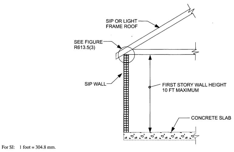
FIGURE R613.5(1)
MAXIMUM ALLOWABLE HEIGHT OF SIP WALLS
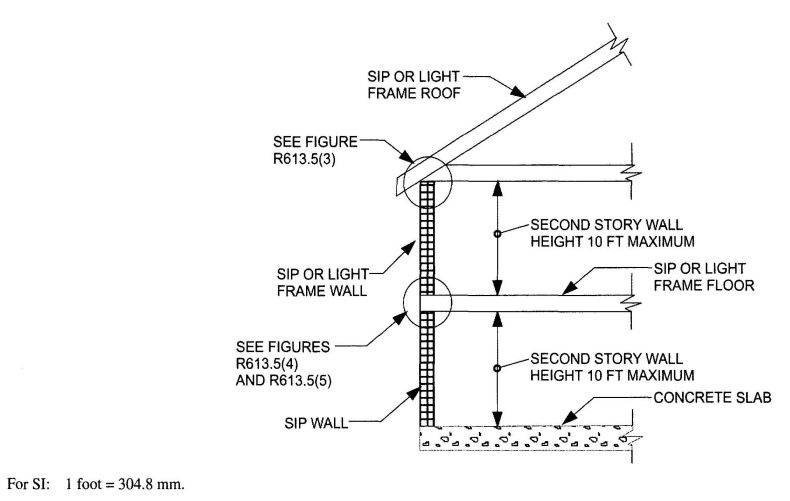
FIGURE R613.5(2)
MAXIMUM ALLOWABLE HEIGHT OF SIP WALLS
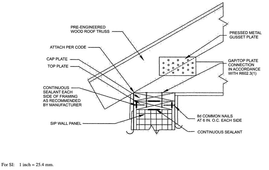
FIGURE R613.5(3)
TRUSSED ROOF TO TOP PLATE CONNECTION
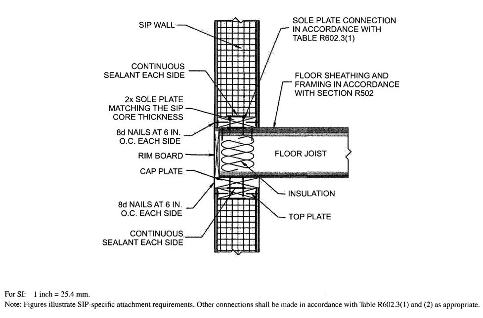
FIGURE R613.5(4)
SIP WALL TO WALL PLATFORM FRAME CONNECTION
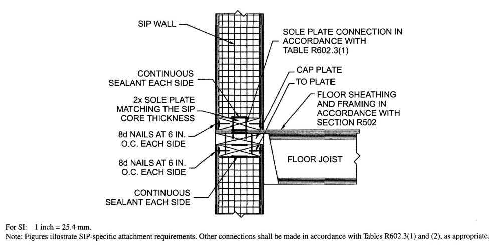
FIGURE R613.5(5)
SIP WALL TO WALL BALLOON FRAME CONNECTION (I-Joist floor shown for Illustration only)
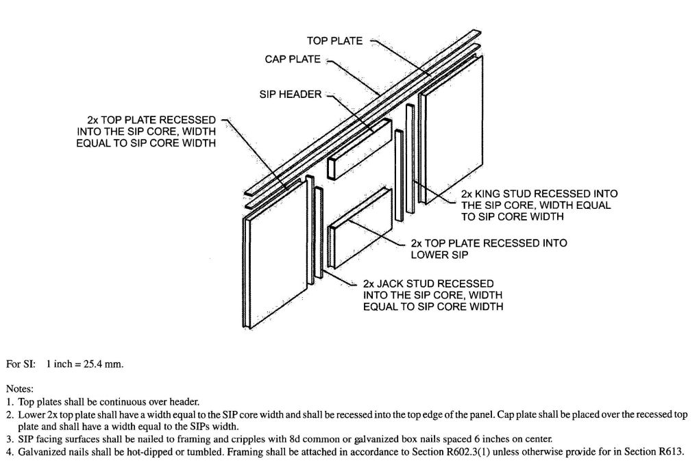
FIGURE R613.5.1
SIP WALL FRAMING CONFIGURATION
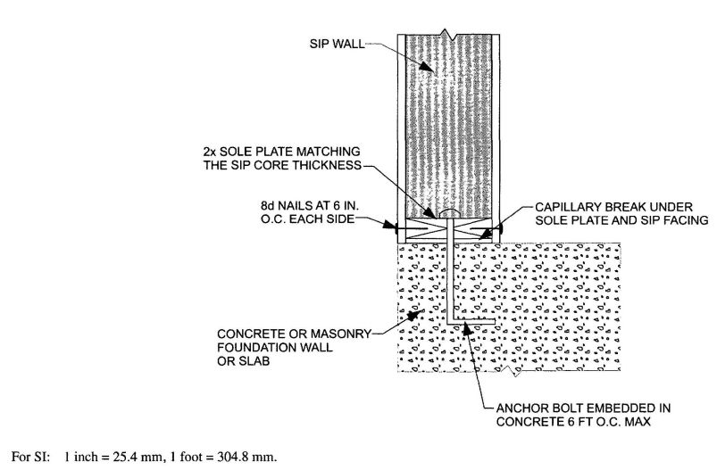
FIGURE R613.5.2
SIP WALL TO CONCRETE SLAB FOR FOUNDATION WALL ATTACHMENT
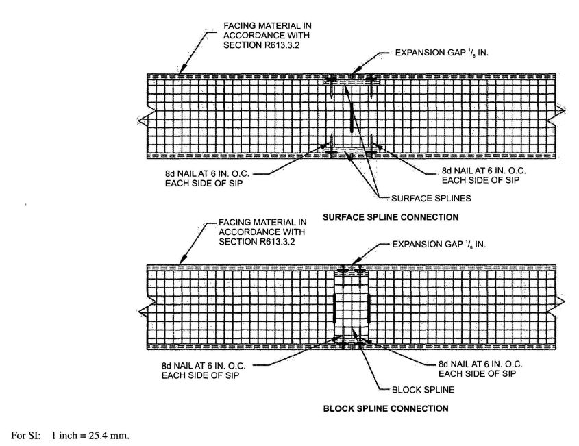
FIGURE R613.8
TYPICAL SIP CONNECTION DETAILS FOR VERTICAL IN-PLANE JOINTS
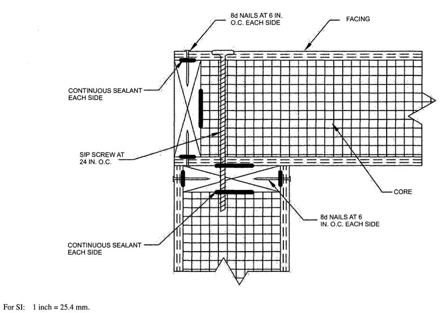
FIGURE R613.9
SIP CORNER FRAMING DETAIL
| LOAD CONDITION | SNOW LOAD (psf) | BUILDING WIDTH (feet) | ||||
|---|---|---|---|---|---|---|
| 24 | 28 | 32 | 36 | 40 | ||
| For SI: 1 inch = 25.4 mm, 1 foot = 304.8 mm. | ||||||
| Maximum deflection criterion: L/360. | ||||||
| Maximum roof dead load: 10 psf. | ||||||
| Maximum ceiling load: 5 psf. | ||||||
| Maximum second floor live load: 30 psf. | ||||||
| Maximum second floor dead load: 10 psf. | ||||||
| Maximum second floor dead load from walls: 10 psf. | ||||||
| N/A indicates not applicable. | ||||||
| Supporting roof only | 20 | 4 | 4 | 4 | 4 | 2 |
| 30 | 4 | 4 | 4 | 2 | 2 | |
| 50 | 2 | 2 | 2 | 2 | 2 | |
| 70 | 2 | 2 | 2 | N/A | N/A | |
| Supporting roof and one-story | 20 | 2 | 2 | N/A | N/A | N/A |
| 30 | 2 | 2 | N/A | N/A | N/A | |
| 50 | 2 | N/A | N/A | N/A | N/A | |
| 70 | N/A | N/A | N/A | N/A | N/A | |
| Adopting agency | BSC | SFM | HCD | DSA | OSHPD | CSA | DPH | AGR | DWR | CEC | CA | SL | SLC | ||||||
|---|---|---|---|---|---|---|---|---|---|---|---|---|---|---|---|---|---|---|---|
| 1 | 2 | 1-AC | AC | SS | 1 | 2 | 3 | 4 | |||||||||||
| Adopt entire chapter | X | X | |||||||||||||||||
| Adopt entire chapter as amended (amended sections listed below) |
|||||||||||||||||||
| Adopt only those sections that are listed below |
|||||||||||||||||||
| Chapter/Section | |||||||||||||||||||
| R703.1.1 | X | X | |||||||||||||||||
R701.1 Application. The provisions of this chapter shall control the design and construction of the interior and exterior wall covering for all buildings.
R701.2 Installation. Products sensitive to adverse weather shall not be installed until adequate weather protection for the installation is provided. Exterior sheathing shall be dry before applying exterior cover.
R702.1 General. Interior coverings or wall finishes shall be installed in accordance with this chapter and Table R702.1(1), Table R702.1(2), Table R702.1(3) and Table R702.3.5. Interior masonry veneer shall comply with the requirements of Section R703.7.1 for support and Section R703.7.4 for anchorage, except an air space is not required. Interior finishes and materials shall conform to the flame spread and smoke-development requirements of Section R302.9.
| PLASTER BASE | FINISHED THICKNESS OF PLASTER FROM FACE OF LATH, MASONRY, CONCRETE (inches) | |
|---|---|---|
| Gypsum Plaster | Cement Plaster | |
| For SI: 1 inch = 25.4 mm. | ||
| a. When measured from back plane of expanded metal lath, exclusive of ribs, or self-furring lath, plaster thickness shall be ¾ inch minimum. | ||
| b. When measured from face of support or backing. | ||
| c. Because masonry and concrete surfaces may very in plane, thickness of plaster need not be uniform. | ||
| d. When applied over a liquid bonding agent, finish coat may be applied directly to concrete surface. | ||
| e. Approved acoustical plaster may be applied directly to concrete or over base coat plaster, beyond the maximum plaster thickness shown. | ||
| f. Attachment shall be in accordance with Table R702.3.5. | ||
| g. Where gypsum board is used as a base for cement plaster, a water-resistive barrier complying with Section R703.2 shall be provided. | ||
| Expanded metal lath | 5/8, minimuma | 5/8, minimuma |
| Wire lath | 5/8, minimuma | ¾, minimum (interior)b 7/8, minimum (exterior)b |
| Gypsum lathg | ½, minimum | ¾, minimum (interior)b |
| Masonry wallsc | ½, minimum | ½, minimum |
| Monolithic concrete wallsc, d | 5/8, maximum | 7/8, maximum |
| Monolithic concrete ceilingsc, d | 3/8, maximume | ½, maximum |
| Gypsum veneer basef, g | 1/16, minimum | ¾, minimum(interior)b |
| Gypsum sheathing g | — | ¾, minimum (interior)b 7/8, minimum (exterior)b |
| NUMBER | COAT | PLASTER BASE OR LATH | MAXIMUM VOLUME AGGREGATE PER 100 POUNDS NEAT PLASTERb (cubic feet) | |
|---|---|---|---|---|
| Damp Loose Sanda | Perlite or Vermiculitec | |||
| For SI: 1 inch = 25.4 mm, 1 cubic foot = 0.0283 m3, 1 pound = 0.454 kg. | ||||
| a. Wood-fibered gypsum plaster may be mixed in the proportions of 100 pounds of gypsum to not more than 1 cubic foot of sand where applied on masonry or concrete. | ||||
| b. When determining the amount of aggregate in set plaster, a tolerance of 10 percent shall be allowed. | ||||
| c. Combinations of sand and lightweight aggregate may be used, provided the volume and weight relationship of the combined aggregate to gypsum plaster is maintained. | ||||
| d. If used for both first and second coats, the volume of aggregate may be 2.5 cubic feet. | ||||
| e. Where plaster is 1 inch or more in total thickness, the proportions for the second coat may be increased to 3 cubic feet. | ||||
| Two-coat work | Base coat | Gypsum lath | 2.5 | 2 |
| Base coat | Masonry | 3 | 3 | |
| Three-coat work | First coat | Lath | 2d | 2 |
| Second coat | Lath | 3d | 2c | |
| First and second coats | Masonry | 3 | 3 | |
| COAT | CEMENT PLASTER TYPE | CEMENTITIOUS MATERIALS | VOLUME OF AGGREGATE PER SUM OF SEPARATE VOLUMES OF CEMENTITIOUS MATERIALSb | |||
|---|---|---|---|---|---|---|
| Portiand Cement Type I, II or III or Blended Cement Type IP, I(PM), IS or I(SM) | Plastic Cement | Masonry Cement Type M, S or N | Lime | |||
| For SI: 1 inch = 25.4 mm, 1 pound = 0.545 kg. | ||||||
| a. Lime by volume of 0 to ¾ shall be used when the plaster will be placed over low-absorption surfaces such as dense clay tile or brick. | ||||||
| b. The same or greater sand proportion shall be used in the second coat than used in the first coat. | ||||||
| First | Portland or blended | 1 | ¾ - 1½a | 2½ - 4 | ||
| Masonry | 1 | 2½ - 4 | ||||
| Plastic | 1 | 2½ - 4 | ||||
| Second | Portland or blended | 1 | ¾ - 1½ | 3 - 5 | ||
| Masonry | 1 | 3 - 5 | ||||
| Plastic | 1 | 3 - 5 | ||||
| Finish | Portland or blended | 1 | ¾ - 2 | 1½ - 3 | ||
| Masonry | 1 | 1½ - 3 | ||||
| Plastic | 1 | 1½ - 3 | ||||
| THICKNESS OF GYPSUM BOARD (inches) | APPLICATION | ORIENTATION OF GYPSUM BOARD TO FRAMING | MAXIMUM SPACING OF FRAMING MEMBERS (inches o.c.) | MAXIMUM SPACING OF FASTENERS (inches) | SIZE OF NAILS FOR APPLICATION TO WOOD FRAMINGc | |
|---|---|---|---|---|---|---|
| Nailsa | Screwsb | |||||
| Application without adhesive | ||||||
| For SI: 1 inch =25.4 mm. | ||||||
| a. For application without adhesive, a pair of nails spaced not less than 2 inches apart or more than 2 1/2 inches apart may be used with the pair of nails spaced 12 inches on center. | ||||||
| b. Screws shall be in accordance with Section R702.3.6. Screws for attaching gypsum board to structural insulated panels shall penetrate the wood structural panel facing not less than 7/16 inch. | ||||||
| c. Where cold-formed steel framing is used with a clinching design to receive nails by two edges of metal, the nails shall be not less than 5/8 inch longer than the gypsum board thickness and shall have ringed shanks. Where the cold-formed steel framing has a nailing groove formed to receive the nails, the nails shall have barbed shanks or be 5d, 13 1/2 gage, 15/8 inches long, 15/64-inch head for 1/2 -inch gypsum board; and 6d,13 gage, 17/8 inches long, 15/64-inch head for 5/8-inch gypsum board. | ||||||
| d. Three-eighths-inch-thick single-ply gypsum board shall not be used on a ceiling where a water-based textured finish is to be applied, or where it will be required to support insulation above a ceiling. On ceiling applications to receive a water-based texture material, either hand or spray applied, the gypsum board shall be applied perpendicular to framing. When applying a water-based texture material, the minimum gypsum board thickness shall be increased from 3/8 inch to 1/2 inch for 16-inch on center framing, and from 1/2 inch to 5/8 inch for 24-inch on center framing or 1/2-inch sag-resistant gypsum ceiling board shall be used. | ||||||
| e. Type X gypsum board for garage ceilings beneath habitable rooms, shall be installed perpendicular to the ceiling framing and shall be fastened at maximum 6 inches o.c. by minimum 17/8 inches 6d coated nails or equivalent drywall screws. | ||||||
| 3/8 | Ceilingd | Perpendicular | 16 | 7 | 12 | 13 gage, 1¼″long, 19/64″ head; 0.098″ diameter, 1¼″ long, annular-ringed; or 4d cooler nail, 0.080″ diameter, 13/8″ long, 7/32″ head. |
| Wall | Either direction | 16 | 8 | 16 | ||
| 1/2 | Ceiling | Either direction | 16 | 7 | 12 | 13 gage, 13/8″ long, 19/64″ head; 0.098″ diameter, 1 1/4″ long, annular-ringed; 5d cooler nail, 0.086″ diameter, 15/8″ long, 15/64″ head; or gypsum board nail, 0.086″ diameter, 15/8″ long, 9/32″ head. |
| Ceilingd | Perpendicular | 24 | 7 | 12 | ||
| Wall | Either direction | 24 | 8 | 12 | ||
| Wall | Either direction | 16 | 8 | 16 | ||
| 5/8 | Ceilingd | Perpendicular | 24 | 7 | 12 | 13 gage, 15/8″ long, 19/64″ head; 0.098″ diameter, 13/8″ long, annular-ringed; 6d cooler nail, 0.092″ diameter, 17/8 ″ long, 1/4″ head; or gypsum board nail, 0.0915″ diameter, 17/8″ long, 19/64″ head. |
| Wall | Either direction | 24 | 7 | 12 | ||
| Wall | Either direction | 16 | 8 | 16 | ||
| Ceiling | Either direction | 16 | 7 | 12 | ||
| Application with adhesive | ||||||
| 3/8 | Ceilingd | Perpendicular | 16 | 16 | 16 | Same as above for 3/8″ gypsum board. |
| Wall | Either direction | 16 | 16 | 24 | ||
| ½ or 5/8 | Ceiling | Either direction | 16 | 16 | 16 | Same as above for 1/2″ and 5/8″ gypsum board, respectively. |
| Ceilingd | Perpendicular | 24 | 12 | 16 | ||
| Wall | Either direction | 24 | 16 | 24 | ||
| Two 3/8 layers | Ceiling | Perpendicular | 16 | 16 | 16 | Base ply nailed as above for 1/2″ gypsum board; face ply installed with adhesive |
| wall | Either direction | 16 | 16 | 16 | ||
R702.2 Interior plaster.
R702.2.1 Gypsum plaster. Gypsum plaster materials shall conform to ASTM C 5, C 28, C 35, C 37, C 59, C 61, C 587, C 588, C 631, C 847, C 933, C 1032 and C 1047, and shall be installed or applied in conformance with ASTM C 843 and C 844. Plaster shall not be less than three coats when applied over metal lath and not less than two coats when applied over other bases permitted by this section, except that veneer plaster may be applied in one coat not to exceed 3/16 inch (4.76 mm) thickness, provided the total thickness is in accordance with Table R702.1(1).
R702.2.2 Cement plaster. Cement plaster materials shall conform to ASTM C 37, C 91 (Type M, S or N), C 150 (Type I, II, and III), C 588, C 595 [Type IP, I (PM), IS and I (SM), C 847, C 897, C 926, C 933, C 1032, C 1047 and C 1328, and shall be installed or applied in conformance with ASTM C 1063. Plaster shall not be less than three coats when applied over metal lath and not less than two coats when applied over other bases permitted by this section, except that veneer plaster may be applied in one coat not to exceed 3/16 inch (4.76 mm) thickness, provided the total thickness is in accordance with Table R702.1(1).
R702.2.2.1 Application. Each coat shall be kept in a moist condition for at least 24 hours prior to application of the next coat.
Exception: Applications installed in accordance with ASTM C 926.
R702.2.2.2 Curing. The finish coat for two-coat cement plaster shall not be applied sooner than 48 hours after application of the first coat. For three coat cement plaster the second coat shall not be applied sooner than 24 hours after application of the first coat. The finish coat for three-coat cement plaster shall not be applied sooner than 48 hours after application of the second coat.
R702.2.3 Support. Support spacing for gypsum or metal lath on walls or ceilings shall not exceed 16 inches (406 mm) for 3/8 inch thick (9.5 mm) or 24 inches (610 mm) for 1/2-inch-thick (12.7 mm) plain gypsum lath. Gypsum lath shall be installed at right angles to support framing with end joints in adjacent courses staggered by at least one framing space.
R702.3 Gypsum board.
R702.3.1 Materials. All gypsum board materials and accessories shall conform to ASTM C 36, C 79, C 475, C 514, C 630, C 931, C 960, C 1002, C 1047, C 1177, C 1178, C 1278, C 1395, C 1396 or C 1658 and shall be installed in accordance with the provisions of this section. Adhesives for the installation of gypsum board shall conform to ASTM C 557.
R702.3.2 Wood framing. Wood framing supporting gypsum board shall not be less than 2 inches (51 mm) nominal thickness in the least dimension except that wood furring strips not less than 1-inch-by-2 inch (25 mm by 51 mm) nominal dimension may be used over solid backing or framing spaced not more than 24 inches (610 mm) on center.
R702.3.3 Cold-formed steel framing. Cold-formed steel framing supporting gypsum board shall not be less than 11/4 inches (32 mm) wide in the least dimension. Nonload-bearing cold-formed steel framing shall comply with ASTM C 645. Load-bearing cold-formed steel framing and all cold-framed steel framing from 0.033 inch to 0.112 inch (1 mm to 3 mm) thick shall comply with ASTM C 955.
R702.3.4 Insulation concrete form walls. Foam plastics for insulating concrete form walls constructed in accordance with Sections R404.1.2 and R611 on the interior of habitable spaces shall be protected in accordance with Section R316.4. Use of adhesives in conjunction with mechanical fasteners is permitted. Adhesives used for interior and exterior finishes shall be compatible with the insulating form materials.
R702.3.5 Application. Maximum spacing of supports and the size and spacing of fasteners used to attach gypsum board shall comply with Table R702.3.5. Gypsum sheathing shall be attached to exterior walls in accordance with Table R602.3(1). Gypsum board shall be applied at right angles or parallel to framing members. All edges and ends of gypsum board shall occur on the framing members, except those edges and ends that are perpendicular to the framing members. Interior gypsum board shall not be installed where it is directly exposed to the weather or to water.
R702.3.6 Fastening. Screws for attaching gypsum board to wood framing shall be Type W or Type S in accordance with ASTM C1002 and shall penetrate the wood not less than 5/8 inch (16 mm). Gypsum board shall be attached to cold-formed steel framing with minimum No. 6 screws. Screws for attaching gypsum board to cold-formed steel framing less than 0.033 inch (1 mm) thick shall be Type S in accordance with ASTM C1002 or bugle head style in accordance with ASTM C1513 and shall penetrate the steel not less than 3/8 inch (9.5 mm). Screws for attaching gypsum board to cold-formed steel framing 0.033 inch to 0.112 inch (1 mm to 3 mm) thick shall be in accordance with ASTM C 954 or bugle head style in accordance with ASTM C1513. Screws for attaching gypsum board to structural insulated panels shall penetrate the wood structural panel facing not less than 7/16 inch (11 mm).
R702.3.7 Horizontal gypsum board diaphragm ceilings. Use of gypsum board shall be permitted on wood joists to create a horizontal diaphragm in accordance with Table R702.3.7. Gypsum board shall be installed perpendicular to ceiling framing members. End joints of adjacent courses of board shall not occur on the same joist. The maximum allowable diaphragm proportions shall be 1 1/2 :1 between shear resisting elements. Rotation or cantilever conditions shall not be permitted. Gypsum board shall not be used in diaphragm ceilings to resist lateral forced imposed by masonry or concrete construction. All perimeter edges shall be blocked using wood members not less than 2-inch (51 mm) by 6-inch (152 mm) nominal dimension. Blocking material shall be installed flat over the top plate of the wall to provide a nailing surface not less than 2 inches (51 mm) in width for the attachment of the gypsum board.
| MATERIAL | THICKNESS OF MATERIAL (min.) (in.) | SPACING OF FRAMING MEMBERS (max.)(in.) | SHEAR VALUEa, b (plf of ceiling) | MINIMUM FASTENER SIZEc, d |
|---|---|---|---|---|
| For SI: 1 inch = 25.4 mm, 1 pound per linear foot = 1.488 kg/m. | ||||
| a. Values are not cumulative with other horizontal diaphragm values and are for short-term loading caused by wind or seismic loading. Values shall be reduced 25 percent for normal loading. | ||||
| b. Values shall be reduced 50 percent in Seismic Design Categories D0, D1 , D2 and E. | ||||
| c. 1¼", #6 Type S or W screws may be substituted for the listed nails. | ||||
| d. Fasteners shall be spaced not more than 7 inches on center at all supports, including perimeter blocking, and not less than 3/8 inch from the edges and ends of the gypsum board. | ||||
| Gypsum board | ½ | 16 o.c. | 90 | 5d cooler or wallboard nail; 1 5/8-inch long; 0.086-inch shank; 15/64-inch head |
| Gypsum board | ½ | 24 o.c. | 70 | 5d cooler or wallboard nail; 1 5/8-inch long; 0.086-inch shank; 15/64-inch head |
R702.3.8 Water-resistant gypsum backing board. Gypsum board used as the base or backer for adhesive application of ceramic tile or other required nonabsorbent finish material shall conform to ASTM C 1396, C 1178 or C 1278. Use of water-resistant gypsum backing board shall be permitted on ceilings where framing spacing does not exceed 12 inches (305 mm) on center for ½-inch-thick (12.7 mm) or 16 inches (406 mm) for 5/8-inch-thick (16 mm) gypsum board. Water-resistant gypsum board shall not be installed over a Class I or II vapor retarder in a shower or tub compartment. Cut or exposed edges, including those at wall intersections, shall be sealed as recommended by the manufacturer.
R702.3.8.1 Limitations. Water resistant gypsum backing board shall not be used where there will be direct exposure to water, or in areas subject to continuous high humidity.
R702.4 Ceramic tile.
R702.4.1 General. Ceramic tile surfaces shall be installed in accordance with ANSI A108.1, A108.4, A108.5, A108.6, A108.11, A118.1, A118.3, A136.1 and A137.1.
R702.4.2 Fiber-cement, fiber-mat reinforced cement, glass mat gypsum backers and fiber-reinforced gypsum backers. Fiber-cement, fiber-mat reinforced cement, glass mat gypsum backers or fiber-reinforced gypsum backers in compliance with ASTM C 1288, C 1325, C 1178 or C 1278, respectively, and installed in accordance with manufacturers’ recommendations shall be used as backers for wall tile in tub and shower areas and wall panels in shower areas.
R702.5 Other finishes. Wood veneer paneling and hardboard paneling shall be placed on wood or cold-formed steel framing spaced not more than 16 inches (406 mm) on center. Wood veneer and hard board paneling less than ¼ inch (6 mm) nominal thickness shall not have less than a 3/8-inch (10 mm) gypsum board backer. Wood veneer paneling not less than ¼-inch (6 mm) nominal thickness shall conform to ANSI/ HPVA H P-1. Hardboard paneling shall conform to CPA/ANSI A 135.5.
R702.6 Wood shakes and shingles. Wood shakes and shingles shall conform to CSSB Grading Rules for Wood Shakes and Shingles and shall be permitted to be installed directly to the studs with maximum 24 inches (610 mm) on-center spacing.
R702.6.1 Attachment. Nails, staples or glue are permitted for attaching shakes or shingles to the wall, and attachment of the shakes or shingles directly to the surface shall be permitted provided the fasteners are appropriate for the type of wall surface material. When nails or staples are used, two fasteners shall be provided and shall be placed so that they are covered by the course above.
R702.6.2 Furring strips. Where furring strips are used, they shall be 1 inch by 2 inches or 1 inch by 3 inches (25 mm by 51 mm or 25 mm by 76 mm), spaced a distance on center equal to the desired exposure, and shall be attached to the wall by nailing through other wall material into the studs.
R703.1 General. Exterior walls shall provide the building with a weather-resistant exterior wall envelope. The exterior wall envelope shall include flashing as described in Section R703.8.
R703.1.1 Water resistance. The exterior wall envelope shall be designed and constructed in a manner that prevents the accumulation of water within the wall assembly by providing a water-resistant barrier behind the exterior veneer as required by Section R703.2 and a means of draining to the exterior water that enters the assembly. Protection against condensation in the exterior wall assembly shall be provided in accordance with the California Energy Code.
Exceptions:
- A weather-resistant exterior wall envelope shall not be required over concrete or masonry walls 416 designed in accordance with Chapter 6 and flashed according to Section R703.7 or R703.8.
- Compliance with the requirements for a means of drainage, and the requirements of Section R703.2 and Section R703.8, shall not be required for an exterior wall envelope that has been demonstrated to resist wind-driven rain through testing of the exterior wall envelope, including joints, penetrations and intersections with dissimilar materials, in accordance with ASTM E 331 under the following conditions:
- Exterior wall envelope test assemblies shall include at least one opening, one control joint, one wall/eave interface and one wall sill. All tested openings and penetrations shall be representative of the intended end-use configuration.
- Exterior wall envelope test assemblies shall be at least 4 feet (1219 mm) by 8 feet (2438 mm) in size.
- Exterior wall assemblies shall be tested at a minimum differential pressure of 6.24 pounds per square foot (299 Pa).
- Exterior wall envelope assemblies shall be subjected to the minimum test exposure for a minimum of 2 hours.
The exterior wall envelope design shall be considered to resist wind-driven rain where the results of testing indicate that water did not penetrate control joints in the exterior wall envelope, joints at the perimeter of openings penetration or intersections of terminations with dissimilar materials.
703.1.2 Wind resistance. Wall coverings, backing materials and their attachments shall be capable of resisting wind loads in accordance with Tables R301.2(2) and R301.2(3). Wind-pressure resistance of the siding and backing materials shall be determined by ASTM E 330 or other applicable standard test methods. Where wind-pressure resistance is determined by design analysis, data from approved design standards and analysis conforming to generally accepted engineering practice shall be used to evaluate the siding and backing material and its fastening. All applicable failure modes including bending rupture of siding, fastener with drawal and fastener head pull-through shall be considered in the testing or design analysis. Where the wall covering and the backing material resist wind load as an assembly, use of the design capacity of the assembly shall be permitted.
R703.2 Water-resistive barrier. One layer of No. 15 asphalt felt, free from holes and breaks, complying with ASTM D 226 for Type 1 felt or other approved water-resistive barrier shall be applied over studs or sheathing of all exterior walls. Such felt or material shall be applied horizontally, with the upper layer lapped over the lower layer not less than 2 inches (51 mm). Where joints occur, felt shall be lapped not less than 6 inches (152 mm). The felt shall be lapped not less than 6 inches (152 mm). The felt or other approved material shall be continuous to the top of walls and terminated at penetrations and building appendages in a manner to meet the requirements of the exterior wall envelope as described in Section R703.1.
Exception: Omission of the water-resistive barrier is permitted in the following situations:
- In detached accessory buildings.
- Under exterior wall finish materials as permitted in Table R703.4.
- Under paperbacked stucco lath when the paper backing is an approved water-resistive barrier.
R703.3 Wood, hardboard and wood structural panel siding.
R703.3.1 Panel siding. Joints in wood, hardboard or wood structural panel siding shall be made as follows unless otherwise approved. Vertical joints in panel siding shall occur over framing members, unless wood or wood structural panel sheathing is used, and shall be shiplapped or covered with a batten. Horizontal joints in panel siding shall be lapped a minimum of 1 inch (25 mm) or shall be shiplapped or shall be flashed with Z-flashing and occur over solid blocking, wood or wood structural panel sheathing.
R703.3.2 Horizontal siding. Horizontal lap siding shall be installed in accordance with the manufacturer’s recommendations. Where there are no recommendations the siding shall be lapped a minimum of 1 inch (25 mm), or ½ inch (13 mm) if rabbeted, and shall have the ends caulked, covered with a batten or sealed and installed over a strip of flashing.
R703.4 Attachments. Unless specified otherwise, all wall coverings shall be securely fastened in accordance with Table R703.4 or with other approved aluminum, stainless steel, zinc-coated or other approved corrosion-resistive fasteners. Where the basic wind speed per Figure R301.2(4) is 110 miles per hour (49 m/s) or higher, the attachment of wall covering shall be designed to resist the component and cladding loads specified in Table R301.2(2), adjusted for height and exposure in accordance with Table R301.2(3).
R703.5 Wood shakes and shingles. Wood shakes and shingles shall conform to CSSB Grading Rules for Wood Shakes and Shingles.
R703.5.1 Application. Wood shakes or shingles shall be applied either single-course or double-course over nominal ½-inch (13 mm) wood-based sheathing or to furring strips over ½-inch (13 mm) nominal nonwood sheathing. A permeable water-resistive barrier shall be provided over all sheathing, with horizontal overlaps in the membrane of not less than 2 inches (51 mm) and veritcal overlaps of not less than 6 inches (152 mm). Where furring strips are used, they shall be 1 inch by 3 inches or 1 inch by 4 inches (25 mm by 76 mm) or 25 mm by 102 mm) and shall be fastened horizontally to the studs with 7d or 8d box nails and shall be spaced a distance on center equal to the actual weather exposure of the shakes or shingles, not to exceed the maximum exposure specified in Table R703.5.2. The spacing between adjacent shingles to allow for expansion shall not exceed ¼ inch (6 mm), and between adjacent shakes, it shall not exceed ½ inch (13 mm). The offset spacing between joints in adjacent courses shall be a minimum of 1½ inches (38 mm).
R703.5.2 Weather exposure. The maximum weather exposure for shakes and shingles shall not exceed that specified in Table R703.5.2.
R703.5.3 Attachment. Each shake or shingle shall be held in place by two hot-dipped zinc-coated, stainless steel, or aluminum nails or staples. The fasteners shall be long enough to penetrate the sheathing or furring strips by a minimum of ½ inch (13 mm) and shall not be overdriven.
R703.5.3.1 Staple attachment. Staples shall not be less than 16 gage and shall have a crown width of not less than 7/16 inch (11 mm), and the crown of the staples shall be parallel with the butt of the shake or shingle. In single-course application, the fasteners shall be concealed by the course above and shall be driven approximately 1 inch (25 mm) above the butt line of the succeeding course and ¾ inch (19 mm) from the edge. In double-course applications, the exposed shake or shingle shall be face-nailed with two casing nails, driven approximately 2 inches (51 mm) above the butt line and ¾ inch (19 mm) from each edge. In all applications, staples shall be concealed by the course above. With shingles wider than 8 inches (203 mm) two additional nails shall be required and shall be nailed approximately 1 inch (25 mm) apart near the center of the shingle.
R703.5.4 Bottom courses. The bottom courses shall be doubled.
R703.6 Exterior plaster. Installation of these materials shall be in compliance with ASTM C 926 and ASTM C 1063 and the provisions of this code.
R703.6.1 Lath. All lath and lath attachments shall be of corrosion-resistant materials. Expanded metal or woven wire lath shall be attached with 1½-inch-long (38 mm), 11 gage nails having a 7⁄16-inch (11.1 mm) head, or 7⁄8;-inch-long (22.2 mm), 16 gage staples, spaced at no more than 6 inches (152 mm), or as otherwise approved.
R703.6.2 Plaster. Plastering with portland cement plaster shall be not less than three coats when applied over metal lath or wire lath and shall be not less than two coats when applied over masonry, concrete, pressure-preservative treated wood or decay-resistant wood as specified in Section R317.1 or gypsum backing. If the plaster surface is completely covered by veneer or other facing material or is completely concealed, plaster application need be only two coats, provided the total thickness is as set forth in Table R702.1(1).
On wood-frame construction with an on-grade floor slab system, exterior plaster shall be applied to cover, but not extend below, lath, paper and screed.
| LENGTH | EXPOSURE FOR SINGLE COURSE | EXPOSURE FOR DOUBLE COURSE |
|---|---|---|
| For SI: 1 inch = 25.4 mm. | ||
| a. Dimensions given are for No. 1 grade. | ||
| b. A maximum 10-inch exposure is permitted for No. 2 grade. | ||
| c. A maximum 11-inch exposure is permitted for No. 2 grade. | ||
| Shinglesa | ||
| 16 | 7½ | 12b |
| 18 | 8½ | 16 |
| 24 | 11½ | 16 |
| Shakesa | ||
| 18 | 8½ | 14 |
| 24 | 11½ | 18 |
The proportion of aggregate to cementitious materials shall be as set forth in Table R702.1(3).
R703.6.2.1 Weep screeds. A minimum 0.019-inch (0.5 mm) (No. 26 galvanized sheet gage), corrosion-resistant weep screed or plastic weep screed, with a minimum vertical attachment flange of 3½ inches (89 mm) shall be provided at or below the foundation plate line on exterior stud walls in accordance with ASTM C 926. The weep screed shall be placed a minimum of 4 inches (102 mm) above the earth or 2 inches (51 mm) above paved areas and shall be of a type that will allow trapped water to drain to the exterior of the building. The weathe-resistant barrier shall lap the attachment flange. The exterior lath shall cover and terminate on the attachment flange of the weep screed.
R703.6.3 Water-resistive barriers. Water-resistive barriers shall be installed as required in Section R703.2 and, where applied over wood-based sheathing, shall include a water-resistive vapor-permeable barrier with a performance at least equivalent to two layers of Grade D paper.
Exception: Where the water-resistive barrier that is applied over wood-based sheathing has a water resistance equal to or greater than that of 60 minute Grade D paper and is separated from the stucco by an intervening, substantially nonwater-absorbing layer or designed drainage space.
R703.6.4 Application. Each coat shall be kept in a moist condition for at least 48 hours prior to application of the next coat.
Exception: Applications installed in accordance with ASTM C 926.
R703.6.5 Curing. The finish coat for two-coat cement plaster shall not be applied sooner than seven days after application of the first coat. For three-coat cement plaster, the second coat shall not be applied sooner than 48 hours after application of the first coat. The finish coat for three-coat cement plaster shall not be applied sooner than seven days after application of the second coat.
R703.7 Stone and masonry veneer, general. Stone and masonry veneer shall be installed in accordance with this chapter, Table R703.4 and Figure R703.7. These veneers installed over a backing of wood or cold-formed steel shall be limited to the first story above-grade and shall not exceed 5 inches (127 mm) in thickness. See Section R602.12 for wall bracing requirements for masonry veneer for wood framed construction and Section R603.9.5 for wall bracing requirements for masonry veneer for cold-formed steel construction.
Exceptions:
- For all buildings in Seismic Design Categories A, B and C, exterior stone or masonry veneer, as specified in Table R703.7(1), with a backing of wood or steel framing shall be permitted to the height specified in Table R703.7(1) above a noncombustible foundation.
- For detached one- or two-family dwellings in Seismic Design Categories D0, D1 and D2, exterior stone or masonry veneer, as specified in Table R703.7(2), with a backing of wood framing shall be permitted to the height specified in Table R703.7(2) above a noncombustible foundation.
R703.7.1 Interior veneer support. Veneers used as interior wall finishes shall be permitted to be supported on wood or cold-formed steel floors that are designed to support the loads imposed.
R703.7.2 Exterior veneer support. Except in Seismic Design Categories D0, D1, D2 exterior masonry veneers having an installed weight of 40 pounds per square foot (195 kg/m2) or less shall be permitted to be supported on wood or cold-formed steel construction. When masonry veneer supported by wood or cold-formed steel construction adjoins masonry veneer supported by the foundation, there shall be a movement joint between the veneer supported by the wood or cold-formed steel construction and the veneer supported by the foundation. The wood or cold-formed steel construction supporting the masonry veneer shall be designed to limit the deflection to 1/600 of the span for the supporting members. The design of the wood or cold-formed steel construction shall consider the weight of the veneer and any other loads.
R703.7.2.1 Support by steel angle. A minimum 6 inches by 4 inches by 5/16 inch (152 mm by 102 mm by 8 mm) steel angle, with the long leg placed vertically, shall be anchored to double 2 inches by 4 inches (51 mm by 102 mm) wood studs at a maximum on-center spacing of 16 inches (406 mm). Anchorage of the steel angle at every double stud spacing shall be a minimum of two 7/16 inch (11 mm) diameter by 4 inch (102 mm) lag screws. The steel angle shall have a minimum clearance to underlying construction of 1/16 inch (2 mm). A minimum of two- thirds the width of the masonry veneer thickness shall bear on the steel angle. Flashing and weep holes shall be located in the masonry veneer wythe in accordance with Figure R703.7.2.1. The maximum height of masonry veneer above the steel angle support shall be 12 feet, 8 inches (3861 mm). The air space separating the masonry veneer from the wood backing shall be in accordance with Sections R703.7.4 and R703.7.4.2. The method of support for the masonry veneer on wood construction shall be constructed in accordance with Figure R703.7.2.1.
The maximum slope of the roof construction without stops shall be 7:12. Roof construction with slopes greater than 7:12 but not more than 12:12 shall have stops of a minimum 3 inch × 3 inch × ¼ inch (76 mm × 76 mm × 6 mm) steel plate welded to the angle at 24 inches (610 mm) on center along the angle or as approved by the building official.
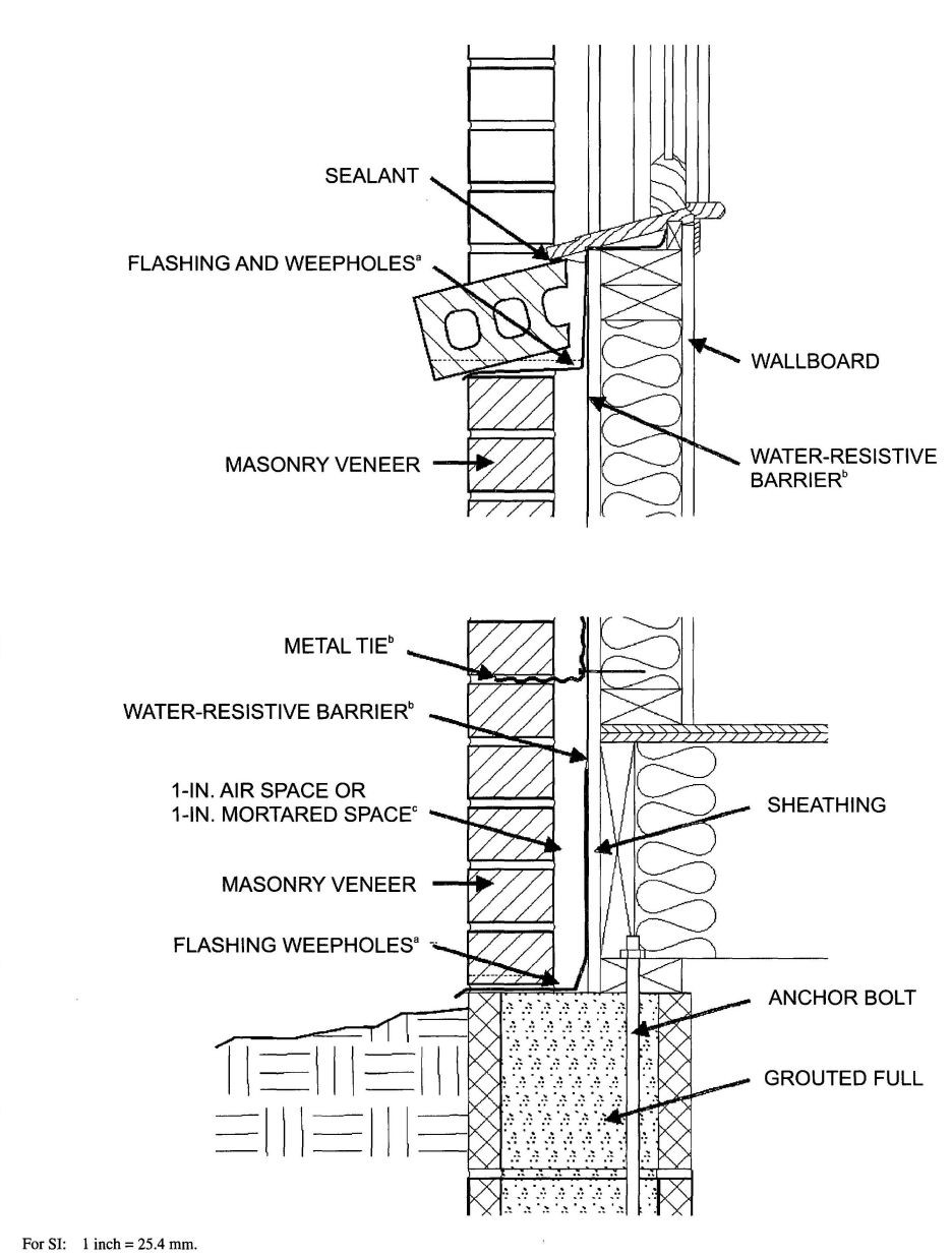
FIGURE R703.7
MASONRY VENEER WALL DETAILS
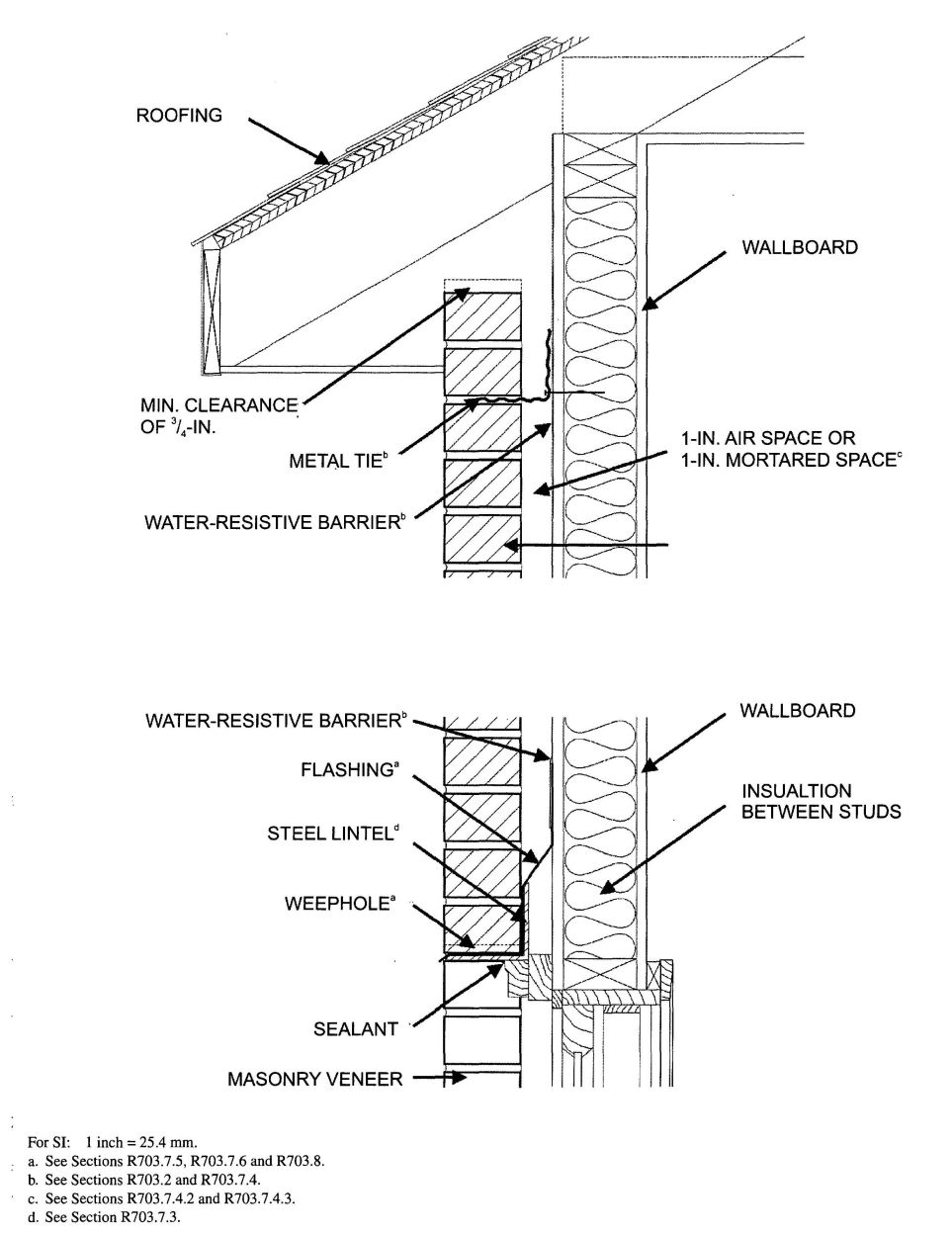
FIGURE R703.7—continued
MASONRY VENEER WALL DETAILS
| SEISMIC DESIGN CATEGORY | NUMBER OF WOOD OR STEEL FRAMED STORIES | MAXIMUM HEIGHT OF VENEER ABOVE NONCOMBUSTIBLE FOUNDATIONa (feet) | MAXIMUM NOMINAL THICKNESS OF VENEER (inches) | MAXIMUM WEIGHT OF VENEER (psf)b | WOOD OR STEEL FRAMED STORY |
|---|---|---|---|---|---|
| For SI: 1 inch = 25.4 mm, 1 foot = 304.8 mm, 1 pound per square foot = 0.479 kPa. | |||||
| a. An Additional 8 feet is permitted for gable end walls. See also story height limitations of Section R301.3. | |||||
| b. Maximum weight is installed weight and includes weight of mortar, grout, lath and other materials used for installation. Where veneer is placed on the both faces of a wall, the combined weight shall not exceed that specified in this table. | |||||
| A or B | Steel: 1 or 2 Wood: 1, 2 or 3 | 30 | 5 | 50 | all |
| C | 1 | 30 | 5 | 50 | 1 only |
| 2 | 30 | 5 | 50 | top | |
| bottom | |||||
| Wood only: 3 | 30 | 5 | 50 | top | |
| middle | |||||
| bottom | |||||
| SEISMIC DESIGN CATEGORY | NUMBER OF WOOD FRAMED STORIESa | MAXIMUM HEIGHT OF VENEER ABOVE NONCOMBUSTIBLE FOUNDATION OR FOUNDATION WALL (feet) | MAXIMUM NOMINAL THICKNESS OF VENEER (inches) | MAXIMUM WEIGHT OF VENEER (psf)b |
|---|---|---|---|---|
| For SI: 1 inch = 25.4 mm, 1 foot = 304.8 mm, 1 pound per square foot = 0.479 kPa, 1 pound-force = 4.448 N. | ||||
| a. Cripple walls are not permitted in Seismic Design Categories D0, D1 and D2 | ||||
| b. Maximum weight is installed weight and includes weight of mortar, grout and lath, and other materials used for installation. | ||||
| c. The veneer shall not exceed 20 feet in height above a noncombustible foundation, with an additional 8 feet permitted for gable end walls, or 30 feet in height with an additional 8 feet for gable end walls where the lower 10 feet has a backing of concrete or masonry wall. See also story height limitations of Section R301.3. | ||||
| d. The veneer shall not exceed 30 feet in height above a noncombustible foundations, with an additional 8 feet permitted for gable end walls. See also story height limitations of Section R301.3. | ||||
| D0 | 1 | 20c | 4 | 40 |
| 2 | 20c | 4 | 40 | |
| 3 | 30c | 4 | 40 | |
| D1 | 1 | 20c | 4 | 40 |
| 2 | 20c | 4 | 40 | |
| 3 | 20c | 4 | 40 | |
| D2 | 1 | 20c | 3 | 30 |
| 2 | 20c | 3 | 30 | |
R703.7.2.2 Support by roof construction. A steel angle shall be placed directly on top of the roof construction. The roof supporting construction for the steel angle shall consist of a minimum of three 2-inch by 6-inch (51 mm by 152 mm) wood members. The wood member abutting the vertical wall stud construction shall be anchored with a minimum of three 5/8-inch (16 mm) diameter by 5-inch (127 mm) lag screws to every wood stud spacing. Each additional roof member shall be anchored by the use of two 10d nails at every wood stud spacing. A minimum of two-thirds the width of the masonry veneer thickness shall bear on the steel angle. Flashing and weep holes shall be located in the masonry veneer wythe in accordance with Figure R703.7.2.2. The maximum height of the masonry veneer above the steel angle support shall be 12 feet, 8 inches (3861 mm). The air space separating the masonry veneer from the wood backing shall be in accordance with Sections R703.7.4 and R703.7.4.2 The support for the masonry veneer on wood construction shall be constructed in accordance with Figure R703.7.2.2.
The maximum slope of the roof construction without stops shall be 7:12. Roof construction with slopes greater than 7:12 but not more than 12:12 shall have stops of a minimum 3 inch ×3 inch × ¼ inch (76 mm ×76 mm× 6 mm) steel plate welded to the angle at 24 inches (610 mm) on center along the angle or as approved by the building official.
R703.7.3 Lintels. Masonry veneer shall not support any vertical load other than the dead load of the veneer above. Veneer above openings shall be supported on lintels of noncombustible materials. The lintels shall have a length of bearing not less than 4 inches (102 mm). Steel lintels shall be shop coated with a rust-inhibitive paint, except for lintels made of corrosion-resistant steel or steel treated with coatings to provide corrosion resistance. Construction of openings shall comply with either Section R703.7.3.1 or 703.7.3.2.
R703.7.3.1 The allowable span shall not exceed the values set forth in Table R703.7.3.1.
R703.7.3.2 The allowable span shall not exceed 18 feet 3 inches (5562 mm) and shall be constructed to comply with Figure R703.7.3.2 and the following:
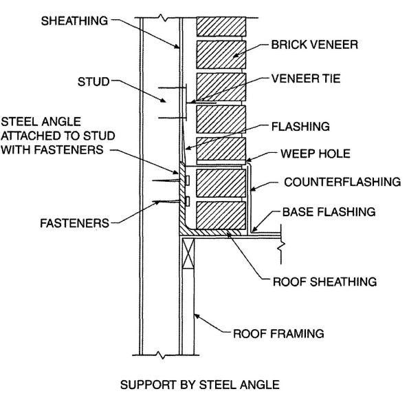
FIGURE R703.7.2.1
EXTERIOR MASONRY VENEER SUPPORT BY STEEL ANGLES
R703.7.4 Anchorage. Masonry veneer shall be anchored to the supporting wall with corrosion-resistant metal ties embedded in mortar or ground and extending into the veneer a minimum of 1½ inches (38 mm), with not less than 5/8 inch (15.9 mm) mortar or grout cover to outside face. Where veneer is anchored to wood backings by corrugated sheet metal ties, the distance separating the veneer from the sheathing material shall be a maximum of a nominal 1 inch (25 mm). Where the veneer is anchored to wood backings using metal strand wire ties, the distance separating the veneer from the sheathing material shall be a maximum of 4½ inches (114 mm). Where the veneer is anchored to cold-formed steel backings, adjustable metal strand wire ties shall be used. Where veneer is anchored to cold-formed steel backings, the distance separating the veneer from the sheathing material shall be a maximum of 4½ inches (114 mm).
R703.7.4.1 Size and spacing. Veneer ties, if strand wire, shall not be less in thickness than No. 9 U.S. gage [(0.148 in.) (4 mm) wire and shall have a hook embedded in the mortar joint, or if sheet metal, shall be not less than No. 22 U.S. gage by [(0.0299 in.) (0.76 mm)] 7/8 inch (22 mm) corrugated. Each tie shall be spaced not more than 24 inches (610 mm) on center horizontally and vertically and shall support not more than 2.67 square feet (0.25 m2) of wall area.
Exception: In Seismic Design Category D0, D1 or D2 or townhouses in Seismic Design Category C or in wind areas of more than 30 pounds per square foot pressure (1.44 kPa), each tie shall support not more than 2 square feet (0.2 m2) of wall area.
R703.7.4.1.1 Veneer ties around wall openings. Veneer ties around wall openings. Additional metal ties shall be provided around all wall openings greater than 16 inches (406 mm) in either dimension. Metal ties around the perimeter of openings shall be spaced not more than 3 feet (9144 mm) on center and placed within 12 inches (305 mm) of the wall opening.
R703.7.4.2 Air space. The veneer shall be separated from the sheathing by an air space of a minimum of a nominal 1 inch (25 mm) but not more than 4½ inches (114 mm).
R703.7.4.3 Mortar or grout fill. As an alternate to the air space required by Section R703.7.4.2, mortar or grout shall be permitted to fill the air space. When the air space is filled with mortar, a water-resistive barrier is required over studs or sheathing. When filling the air space, replacing the sheathing and water-resistive barrier with a wire mesh and approved water-resistive barrier or an approved water-resistive barrier-backed reinforcement attached directly to the studs is permitted.
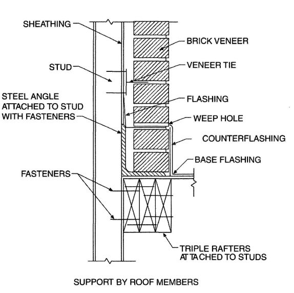
FIGURE R703.7.2.2
EXTERIOR MASONRY VENEER SUPPORT BY ROOF MEMBERS
R703.7.5 Flashing. Flashing shall be located beneath the first course of masonry above finished ground level above the foundation wall or slab and at other points of support, including structural floors, shelf angles and lintels when masonry veneers are designed in accordance with Section R703.7. See Section R703.8 for additional requirements.
R703.7.6 Weepholes. Weepholes shall be provided in the outside wythe of masonry walls at a maximum spacing of 33 inches (838 mm) on center. Weepholes shall not be less than 3/16 inch (5 mm) in diameter. Weepholes shall be located immediately above the flashing.
R703.8 Flashing. Approved corrosion-resistant flashing shall be applied shingle-fashion in a manner to prevent entry of water into the wall cavity or penetration of water to the building structural framing components. Self-adhered membranes used as flashing shall comply with AAMA 711. The flashing shall extend to the surface of the exterior wall finish. Approved corrosion-resistant flashings shall be installed at all of the following locations:
| SIZE OF STEEL ANGLEa,c,d (inches) | NO STORY ABOVE | ONE STORY ABOVE | TWO STORIES ABOVE | NO.OF ½″ OR EQUIVALENT REINFORCING BARS IN REINFORCED LINTELb,d |
|---|---|---|---|---|
| For SI: 1 inch = 25.4 mm, 1 foot = 304.8 mm. | ||||
| a. Long leg of the angle shall be placed in a vertical position. | ||||
| b. Depth of reinforced lintels shall not be less than 8 inches and all cells of hollow masonry lintels shall be grouted solid. Reinforcing bars shall extend not less than 8 inches into the support. | ||||
| c.Steel members indicated are adequate typical examples; other steel members meeting structural design requirements may be used. | ||||
| d. Either steel angle or reinforced lintel shall span opening. | ||||
| 3 × 3 × ¼ | 6′;-0″ | 4′;-6″ | 3′;-0″ | 1 |
| 4 × 3 × ¼ | 8′;-0″ | 6′;-0″ | 4′;-6″ | 1 |
| 5 × 3½ × 5/16 | 10′; -0″ | 8′;-0″ | 6′;-0″ | 2 |
| 6 × 3½ × 5/16 | 14′;-0″ | 9′;-6″ | 7′;-0″ | 2 |
| 2-6 × 3½ × 5/16 | 20′; -0″ | 12′;-0″ | 9′;-6″ | 4 |
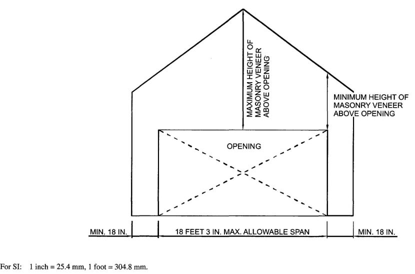
FIGURE R703.7.3.2
MASONRY VENEER OPENING
R703.9 Exterior insulation and finish system (EIFS)/EIFS with drainage. Exterior Insulation and Finish System (EIFS) shall comply with this chapter and Sections R703.9.1 and R703.9.3. EIFS with drainage shall comply with this chapter and Sections R703.9.2, R703.9.3 and R703.9.4.
R703.9.1 Exterior insulation and finish system (EIFS). EIFS shall comply with ASTM E 2568.
R703.9.2 Exterior insulation and finish system (EIFS) with drainage. EIFS with drainage shall comply with ASTM E 2568 and shall have an average minimum drainage efficiency of 90 percent when tested in accordance with ASTM E 2273.
R703.9.2.1 Water-resistive barrier. The water-resistive barrier shall comply with Section R703.2 or ASTM E 2570.
R703.9.2.2 Installation. The water-resistive barrier shall be applied between the EIFS and the wall sheathing.
R703.9.3 Flashing, general. Flashing of EIFS shall be provided in accordance with the requirements of Section R703.8.
R703.9.4 EIFS/EIFS with drainage installation. All EIFS shall be installed in accordance with the manufacturer’s installation instructions and the requirements of this section.
R703.9.4.1 Terminations. The EIFS shall terminate not less than 6 inches (152 mm) above the finished ground level.
R703.9.4.2 Decorative trim. Decorative trim shall not be face nailed though the EIFS.
R703.10 Fiber cement siding.
R703.10.1 Panel siding. Fiber-cement panels shall comply with the requirements of ASTM C1186, Type A, minimum Grade II. Panels shall be installed with the long dimension either parallel or perpendicular to framing. Vertical and horizontal joints shall occur over framing members and shall be sealed with caulking, covered with battens or shall be designed to comply with Section R703.1. Panel siding shall be installed with fasteners according to Table R703.4 or approved manufacturer’s installation instructions.
R703.10.2 Lap siding. Fiber-cement lap siding having a maximum width of 12 inches shall comply with the requirements of ASTM C1186, Type A, minimum Grade II. Lap siding shall be lapped a minimum of 1¼ inches (32 mm) and lap siding not having tongue-and-groove end joints shall have the ends sealed with caulking, installed with an H-section joint cover, located over a strip of flashing or shall be designed to comply with Section R703.1. Lap siding courses may be installed with the fastener heads exposed or concealed, according to Table R703.4 or approved manufacturers’s installation instructions.
R703.11 Vinyl siding. Vinyl siding shall be certified and labeled as conforming to the requirements of ASTM D 3679 by an approved quality control agency.
R703.11.1 Installation. Vinyl siding, soffit and accessories shall be installed in accordance with the manufacturer’s installation instructions.
R703.11.1.1 Soffit panels shall be individually fastened to a supporting component such as a nailing strip, fascia or subfascia component or as specified by the manufacturer’s instructions.
R703.11.2 Foam plastic sheathing. Vinyl siding used with foam plastic sheathing shall be installed in accordance with Section R703.11.2.1, R703.11.2.2, or R703.11.2.3.
Exception: Where the foam plastic sheathing is applied directly over wood structural panels, fiberboard, gypsum sheathing or other approved backing capable of independently resisting the design wind pressure, the vinyl siding shall be installed in accordance with Section R703.11.1.
R703.11.2.1 Basic wind speed not exceeding 90 miles per hour and Exposure Category B. Where the basic wind speed does not exceed 90 miles per hour (40 m/s), the Exposure Category is B and gypsum wall board or equivalent is installed on the side of the wall opposite the foam plastic sheathing, the minimum siding fastener penetration into wood framing shall be 1¼ inches (32 mm) using minimum 0.120-inch diameter nail (shank) with a minimum 0.313-inch diameter head, 16 inches on center. The foam plastic sheathing shall be minimum ½ -inch-thick (12.7 mm) (nominal) extruded polystyrene per ASTM C578, ½-inch-thick (12.7 mm) (nominal) polyisocyanurate per ASTM C1289, or 1-inch-thick (25 mm) (nominal) expanded polystyrene per ASTM C578.
R703.11.2.2 Basic wind speed exceeding 90 miles per hour or Exposure Categories C and D. Where the basic wind speed exceeds 90 miles per hour (40 m/s) or the Exposure Category is C or D, or all conditions of Section R703.11.2.1 are not met, the adjusted design pressure rating for the assembly shall meet or exceed the loads listed in Tables R301.2(2) adjusted for height and exposure using Section R301.2(3). The design wind pressure rating of the vinyl siding for installation over solid sheathing as provided in the vinyl siding manufacturer’s product specifications shall be adjusted for the following wall assembly conditions:
R703.11.2.3 Manufacturer specification. Where the vinyl siding manufacturer’s product specifications provide an approved design wind pressure rating for installation over foam plastic sheathing, use of this design wind pressure rating shall be permitted and the siding shall be installed in accordance with the manufacturer’s installation instructions.
R703.12 Adhered masonry veneer installation. Adhered masonry veneer shall be installed in accordance with the manufacturer’s instructions.
| Adopting agency | BSC | SFM | HCD | DSA | OSHPD | CSA | DPH | AGR | DWR | CEC | CA | SL | SLC | ||||||
|---|---|---|---|---|---|---|---|---|---|---|---|---|---|---|---|---|---|---|---|
| 1 | 2 | 1-AC | AC | SS | 1 | 2 | 3 | 4 | |||||||||||
| Adopt entire chapter | |||||||||||||||||||
| Adopt entire chapter as amended (amended sections listed below) | X | X | |||||||||||||||||
| Adopt only those sections that are listed below | X | ||||||||||||||||||
| Chapter/Section | |||||||||||||||||||
| R802.1 | X | X | |||||||||||||||||
| R802.1.3.4 | X | X | |||||||||||||||||
| R802.1.3 through R802.1.3.8 | X | ||||||||||||||||||
| R802.10.2 | X | X | |||||||||||||||||
| R806.4 | X | X | |||||||||||||||||
| R807.1 | X | X | |||||||||||||||||
R801.1 Application. The provisions of this chapter shall control the design and construction of the roof-ceiling system for all buildings.
R801.2 Requirements. Roof and ceiling construction shall be capable of accommodating all loads imposed according to Section R301 and of transmitting the resulting loads to the supporting structural elements.
R801.3 Roof drainage. In areas where expansive or collapsible soils are known to exist, all dwellings shall have a controlled method of water disposal from roofs that will collect and discharge roof drainage to the ground surface at least 5 feet (1524 mm) from foundation walls or to an approved drainage system.
R802.1 Identification. Load-bearing dimension lumber for rafters, trusses and ceiling joists shall be identified by a grade mark of a lumber grading or inspection agency that has been approved by an accreditation body that complies with DOC PS 20. In lieu of a grade mark, a certificate of inspection issued by a lumber grading or inspection agency meeting the requirements of this section shall be accepted.
Note: See Section R301.1.1.1 for limited-density owner-built rural dwellings.
R802.1.1 Blocking. Blocking shall be a minimum of utility grade lumber.
R802.1.2 End-jointed lumber. Approved end-jointed lumber identified by a grade mark conforming to Section R802.1 may be used interchangeably with solid-sawn members of the same species and grade.
R802.1.3 Fire-retardant-treated wood. Fire-retardant-treated wood (FRTW) is any wood product which, when impregnated with chemicals by a pressure process or other means during manufacture, shall have, when tested in accordance with ASTM E 84, a listed flame spread index of 25 or less and shows no evidence of significant progressive combustion when the test is continued for an additional 20-minute period. In addition, the flame front shall not progress more than 10.5 feet (3200 mm) beyond the center line of the burners at any time during the test.
R802.1.3.1 Pressure process. For wood products impregnated with chemicals by a pressure process, the process shall be performed in closed vessels under pressures not less than 50 pounds per square inch gauge (psig) (344.7 kPa).
R802.1.3.2 Other means during manufacture. For wood products produced by other means during manufacture the treatment shall be an integral part of the manufacturing process of the wood product. The treatment shall provide permanent protection to all surfaces of the wood product.
R802.1.3.3 Testing. For wood products produced by other means during manufacture, other than a pressure process, all sides of the wood product shall be tested in accordance with and produce the results required in Section R802.1.3. Testing of only the front and back faces of wood structural panels shall be permitted.
R802.1.3.4 Labeling. Fire-retardant-treated lumber and wood structural panels shall be labeled. The label shall contain:
R802.1.3.5 Strength adjustments. Design values for untreated lumber and wood structural panels as specified in Section R802.1 shall be adjusted for fire-retardant-treated wood. Adjustments to design values shall be based upon an approved method of investigation which takes into consideration the effects of the anticipated temperature and humidity to which the fire-retardant-treated wood will be subjected, the type of treatment and redrying procedures.
R802.1.3.5.1 Wood structural panels. The effect of treatment and the method of redrying after treatment, and exposure to high temperatures and high humidities on the flexure properties of fire-retardant-treated softwood plywood shall be determined in accordance with ASTM D 5516. The test data developed by ASTM D 5516 shall be used to develop adjustment factors, maximum loads and spans, or both for untreated plywood design values in accordance with ASTM D 6305. Each manufacturer shall publish the allowable maximum loads and spans for service as floor and roof sheathing for their treatment.
R802.1.3.5.2 Lumber. For each species of wood treated, the effect of the treatment and the method of redrying after treatment and exposure to high temperatures and high humidities on the allowable design properties of
431fire-retardant-treated lumber shall be determined in accordance with ASTM D 5664. The test data developed by ASTM D 5664 shall be used to develop modification factors for use at or near room temperature and at elevated temperatures and humidity in accordance with ASTM D 6841. Each manufacturer shall publish the modification factors for service at temperatures of not less than 80°F (27°C) and for roof framing. The roof framing modification factors shall take into consideration the climatological location.
R802.1.3.6 Exposure to weather. Where fire-retardant-treated wood is exposed to weather or damp or wet locations, it shall be identified as “Exterior” to indicate there is no increase in the listed flame spread index as defined in Section R802.1.3 when subjected to ASTM D 2898.
R802.1.3.7 Interior applications. Interior fire-retardant-treated wood shall have a moisture content of not over 28 percent when tested in accordance with ASTM D 3201 procedures at 92 percent relative humidity. Interior fire-retardant-treated wood shall be tested in accordance with Section R802.1.3.5.1 or R802.1.3.5.2. Interior fire-retardant-treated wood designated as Type A shall be tested in accordance with the provisions of this section.
R802.1.3.8 Moisture content. Fire-retardant-treated wood shall be dried to a moisture content of 19 percent or less for lumber and 15 percent or less for wood structural panels before use. For wood kiln dried after treatment (KDAT) the kiln temperatures shall not exceed those used in kiln drying the lumber and plywood submitted wood and R802.1.3.5.2 for lumber.
R802.1.4 Structural glued laminated timbers. Glued laminated timbers shall be manufactured and identified as required in ANSI/AITC A 190.1 and ASTM D 3737.
R802.1.5 Structural log members. Stress grading of structural log members of nonrectangular shape, as typically used in log buildings, shall be in accordance with ASTM D 3957. Such structural log members shall be identified by the grade mark of an approved lumber grading or inspection agency. In lieu of a grade mark on the material, a certificate of inspection as to species and grade issued by a lumber-grading or inspection agency meeting the requirements of this section shall be permitted to be accepted.
R802.2 Design and construction. The framing details required in Section R802 apply to roofs having a minimum slope of three units vertical in 12 units horizontal (25-percent slope) or greater. Roof-ceilings shall be designed and constructed in accordance with the provisions of this chapter and Figures R606.11(1), R606.11(2) and R606.11(3) or in accordance with AFPA/NDS. Components of roof-ceilings shall be fastened in accordance with Table R602.3(1).
R802.3 Framing details. Rafters shall be framed to ridge board or to each other with a gusset plate as a tie. Ridge board shall be at least 1-inch (25 mm) nominal thickness and not less in depth than the cut end of the rafter. At all valleys and hips there shall be a valley or hip rafter not less than 2-inch (51 mm) nominal thickness and not less in depth than the cut end of the rafter. Hip and valley rafters shall be supported at the ridge by a brace to a bearing partition or be designed to carry and distribute the specific load at that point. Where the roof pitch is less than three units vertical in 12 units horizontal (25-percent slope), structural members that support rafters and ceiling joists, such as ridge beams, hips and valleys, shall be designed as beams.
R802.3.1 Ceiling joist and rafter connections. Ceiling joists and rafters shall be nailed to each other in accordance with Table R802.5.1 (9), and the rafter shall be nailed to the top wall plate in accordance with Table R602.3(1). Ceiling joists shall be continuous or securely joined in accordance with Table R802.5.1(9) where they meet over interior partitions and are nailed to adjacent rafters to provide a continuous tie across the building when such joists are parallel to the rafters.
Where ceiling joists are not connected to the rafters at the top wall plate, joists connected higher in the attic shall be installed as rafter ties, or rafter ties, or rafter ties shall be installed to provide a continuous tie. Where ceiling joists are not parallel to rafters, rafter ties shall be installed. Rafter ties shall be a minimum of 2-inch by 4-inch (51 mm by 102 mm) (nominal), installed in accordance with the connection requirements in Table R802.5.1(9), or connections of equivalent capacities shall be provided. Where ceiling joists or rafter ties are not provided, the ridge formed by these rafters shall be supported by a wall or girder designed in accordance with accepted engineering practice.
Collar ties or ridge straps to resist wind uplift shall be connected in the upper third of the attic space in accordance with Table R602.3(1).
Collar ties shall be a minimum of 1-inch by 4-inch (25 mm by 102 mm) (nominal), spaced not more than 4 feet (1219 mm) on center.
R802.3.2 Ceiling joists lapped. Ends of ceiling joists shall be lapped a minimum of 3 inches (76 mm) or butted over bearing partitions or beams and toenailed to the bearing member. When ceiling joists are used to provide resistance to rafter thrust, lapped joists shall be nailed together in accordance with Table R602.3(1) and butted joists shall be tied together in a manner to resist such thrust.
R802.4 Allowable ceiling joist spans. Spans for ceiling joists shall be in accordance with Tables R802.4(1) and R802.4(2). For other gradesand species and for other loading conditions, refer to the AF&PA Span Tables for Joists and Rafters.
R802.5 Allowable rafter spans. Spans for rafters shall be in accordance with Table R802.5.1(1) through R802.5.1(8). For other gradesand species and for other loading conditions, refer to the AF&PA Span Tables for Joists and Rafters. The span of each rafter shall be measured along the horizontal projection of the rafter.
R802.5.1 Purlins. Installation of purlins to reduce the span of rafters is permitted as shown in Figure R802.5.1. Purlins shall be sized no less than the required size of the rafters that they support. Purlins shall be continuous and shall be supported by 2-inch by 4-inch (51 mm by 102 mm) braces installed to bearing walls at a slope not less than 45 degrees from the horizontal. The braces shall be spaced not more than 4 feet (1219 mm) on center and the unbraced length of braces shall not exceed 8 feet (2438 mm).
R802.6 Bearing. The ends of each rafter or ceiling joist shall have not less than 1½ inches (38 mm) of bearing on wood or metal and not less than 3 inches (76 mm) on masonry or concrete.
R802.6.1 Finished ceiling material. If the finished ceiling material is installed on the ceiling prior to the attachment of the ceiling to the walls, such as in construction at a factory, a compression strip of the same thickness as the finish ceiling material shall be installed directly above the top plate of bearing walls if the compressive strength of the finish ceiling material is less than the loads it will be required to with stand. The compression strip shall cover the entire length of such top plate and shall be at least one-half the width of the top plate. It shall be of material capable of transmitting the loads transferred through it.
R802.7 Cutting and notching. Structural roof members shall not be cut, bored or notched in excess of the limitations specified in this section.
R802.7.1 Sawn lumber. Not ches in solid lumber joists, rafters, blocking and beams shall not exceed one-sixth of the depth of the member, shall not be longer than one-third of the depth of the member and shall not be located in the middle one-third of the span. Notches at the ends of the member shall not exceed one-fourth the depth of the member. The tension side of members 4 inches (102 mm) or greater in nominal thickness shall not be notches except at the ends of the members. The diameter of the holes bored or cut into members shall not exceed one-third the depth of the member. Holes shall not be closer than 2 inches (51 mm) to the top or bottom of the member, or to any other hole located in the member. Where the member is also notched, the hole shall not be closer than 2 inches (51 mm) to the notch.
Exception: Notches on cantilevered portions of rafters are permitted provided the dimension of the remaining portion of the rafter is not less than 4-inch nominal (102 mm) and the length of the cantilever does not exceed 24 inches (610 mm).
R802.7.2 Engineered wood products. Cuts, notches and holes bored in trusses, structural composite lumber, structural glue-laminated members or I-joists are prohibited except where permitted by the manufacturer’s recommendations or where the effects of such alternations are specifically considered in the design of the member by a registered design professional.
R802.8 Lateral support. Roof framing members and ceiling joists having a depth-to-thickness ratio exceeding 5 to 1 based on nominal dimensions shall be provided with lateral support at points of bearing to prevent rotation. For roof rafters with ceiling joists attached per Table R602.3(1), the depth-thickness ratio for the total assembly shall be determined using the combined thickness of the rafter plus the attached ceiling joist.
Exception: Roof trusses shall be braced in accordance with Section R802.10.3.
R802.8.1 Bridging. Rafters and ceiling joists having a depth-to-thickness ratio exceeding 6 to 1 based on nominal dimensions shall be supported laterally by solid blocking, diagonal bridging (wood or metal) or a continuous 1-inch by 3-inch (25 mm by 76 mm) wood strip nailed across the rafters or ceiling joists at intervals not exceeding 8 feet (2438 mm).
R802.9 Framing of openings. Openings in roof and ceiling framing shall be framed with header and trimmer joists. When the header joist span does not exceed 4 feet (1219 mm), the header joist may be a single member the same size as the ceiling joist or rafter. Single trimmer joists may be used to carry a single header joist that is located within 3 feet (914 mm) of the trimmer joist bearing. When the header joist span exceeds 4 feet (1219 mm), the trimmer joists and the header joist shall be doubled and of sufficient cross section to support the ceiling joists or rafter framing into the header. Approved hangers shall be used for the header joist to trimmer joist connections when the header joist span exceeds 6 feet (1829 mm). Tail joists over 12 feet (3658 mm) long shall be supported at the header by framing anchors or on leder strips not less than 2 inches by 2 inches (51 mm by 51 mm).
R802.10 Wood trusses.
R802.10.1 Truss design drawings. Truss design drawings, prepared in conformance to Section R802.10.1, shall be provided to the building official and approved prior to installation. Truss design drawings shall include, at a minimum, the information specified below. Truss design drawing shall be provided with the shipment of trusses delivered to the jobsite.
R802.10.2 Design. Wood trusses shall be designed in accordance with accepted engineering practice. The design and manufacture of metal-plate-connected wood trusses shall comply with ANSI/TPI 1. The truss design drawings shall be prepared by a registered professional where required by the statutes of the State of California or the jurisdiction in which the project is to be constructed.
R802.10.2.1 Applicability limits. The provisions of this section shall control the design of truss roof framing when snow controls for buildings not greater than 60 feet (18 288 mm) in length perpendicular to the joist, rafter or truss span, not greater than 36 feet (10 973 mm) in width parallel to the joist, rafter or truss span, not greater than two stories in height with each story not greater than 10 feet (3048 mm) high, and roof slopes not smaller than 3:12 (25-percent slope) or greater than 12:12 (100-percent slope). Truss roof framing constructed in accordance with the provisions of this section shall be limited to sites subjected to a maximum design wind speed of 110 miles per hour (49 m/s), Exposure A, B or C, and a maximum ground snow load of 70 psf (3352 Pa). For consistent loading of all truss types, roof snow load is to be computed as: 0.7 pg.
R802.10.3 Bracing. Trusses shall be braced to prevent rotation and provide lateral stability in accordance with the requirements specified in the construction documents for the building and on the individual truss design drawings. In the absence of specific bracing requirements, trusses shall be braced in accordance with the Building Component Safety Information (BCSI 1-03) Guide to Good Practice for Handling, Installing & Bracing of Metal Plate Connected Wood Trusses.
R802.10.4 Alterations to trusses. Truss members shall not be cut, notched, drilled, spliced or otherwise altered in any way without the approval of a registered design professional. Alterations resulting in the addition of load (e.g., HVAC equipment, water heater) that exceeds the design load for the truss shall not be permitted without verification that the truss is capable of supporting such additional loading.
R802.10.5 Truss to wall connection. Trusses shall be connected to wall plates by the use of approved connectors having a resistance to uplift of not less than 175 pounds (779 N) and shall be installed in accordance with the manufacturer's specifications. For roof assemblies subject to wind uplift pressures of 20 pounds per square foot (960 Pa) or greater, as established in Table R301.2(2), adjusted for height and exposure per Table R301.2(3), see section R802.11.
R802.11 Roof tie-down.
R802.11.1 Uplift resistance. Roof assemblies which are subject to wind uplift pressures of 20 pounds per square foot (960 Pa) or greater shall have roof rafters or trusses attached to their supporting wall assemblies by connections capable of providing the resistance required in Table R802.11. Wind uplift pressures shall be determined using an effective wind area of 100 square feet (9.3 m2) and Zone 1 in Table R301.2(2), as adjusted for height and exposure per Table R301.2(3).
A continuous load path shall be designed to transmit the uplift forces from the rafter or truss ties to the foundation.
| RAFTER SLOPE | RAFTER SPACING (inches) | GROUND SNOW LOAD (psf) | |||||||||||||||
|---|---|---|---|---|---|---|---|---|---|---|---|---|---|---|---|---|---|
| 20g | 30 | 50 | 70 | ||||||||||||||
| Roof span (feet) | |||||||||||||||||
| 12 | 20 | 28 | 36 | 12 | 20 | 28 | 36 | 12 | 20 | 28 | 36 | 21 | 20 | 28 | 36 | ||
| Required number of 16d common nailsa, b, per heel joint splicesc, d, e, f | |||||||||||||||||
| For SI: 1 inch =25.4 mm, 1 foot=304.8 mm, 1 pound per square foot =0.0479kPa. | |||||||||||||||||
| a. 40d box nails shall be permitted to be substituted for 16d common nails. | |||||||||||||||||
| b. Nailing requirements shall be permitted to be reduced 25 percent if nails are clinched. | |||||||||||||||||
| c. Heel joint connections are not required when the ridge is supported by a load-bearing wall, header or ridge beam. | |||||||||||||||||
| d. When intermediate support of the rafter is provided by vertical struts or purlins to a loadbearing wall, the tabulated heel joint connection requirements shall be permitted to be reduced proportionally to the reduction in span. | |||||||||||||||||
| e. Equivalent nailing patterns are required for ceiling joist to ceiling joist lap splices. | |||||||||||||||||
| f. When rafter ties are substituted for ceiling joists, the heel joint connection requirement shall be taken as the tabulated heel joint connection requirement for two-thirds of the actual rafter-slope. | |||||||||||||||||
| g. Applies to roof live load of 20 psf or less. | |||||||||||||||||
| h. Tabulated heel joint connection requirements assume that ceiling joists or rafter ties are located at the bottom of the attic space. when ceiling joists or rafter ties are located higher in the attic, heel joint connection requirements shall be increased by the following factors: | |||||||||||||||||
| HCHR | Heel Joint Connection Adjustment Factor | ||||||||||||||||
| 1/3 | 1.5 | ||||||||||||||||
| 1/4 | 1.33 | ||||||||||||||||
| 1/5 | 1.25 | ||||||||||||||||
| 1/6 | 1.2 | ||||||||||||||||
| 1/10 or less | 1.11 | ||||||||||||||||
| where: | |||||||||||||||||
| HC =Height of ceiling joists or rafter ties measured vertically above the top of the rafter support walls. | |||||||||||||||||
| HR = Height of roof ridge measured vertically above the top of the rafter support wall. | |||||||||||||||||
| 3:12 | 12 | 4 | 6 | 8 | 10 | 4 | 6 | 8 | 11 | 5 | 8 | 12 | 15 | 6 | 11 | 15 | 20 |
| 16 | 5 | 8 | 10 | 13 | 5 | 8 | 11 | 14 | 6 | 11 | 15 | 20 | 8 | 14 | 20 | 26 | |
| 24 | 7 | 11 | 15 | 19 | 7 | 11 | 16 | 21 | 9 | 16 | 23 | 30 | 12 | 21 | 30 | 39 | |
| 4:12 | 12 | 3 | 5 | 6 | 8 | 3 | 5 | 6 | 8 | 4 | 6 | 9 | 11 | 5 | 8 | 12 | 15 |
| 16 | 4 | 6 | 8 | 10 | 4 | 6 | 8 | 11 | 5 | 8 | 12 | 15 | 6 | 11 | 15 | 20 | |
| 24 | 5 | 8 | 12 | 15 | 5 | 9 | 12 | 16 | 7 | 12 | 17 | 22 | 9 | 16 | 23 | 29 | |
| 5:12 | 12 | 3 | 4 | 5 | 6 | 3 | 4 | 5 | 7 | 3 | 5 | 7 | 9 | 4 | 7 | 9 | 12 |
| 16 | 3 | 5 | 6 | 8 | 3 | 5 | 7 | 9 | 4 | 7 | 9 | 12 | 5 | 9 | 12 | 16 | |
| 24 | 4 | 7 | 9 | 12 | 4 | 7 | 10 | 13 | 6 | 10 | 14 | 18 | 7 | 13 | 18 | 23 | |
| 7:12 | 12 | 3 | 4 | 4 | 5 | 3 | 3 | 4 | 5 | 3 | 4 | 5 | 7 | 3 | 5 | 7 | 9 |
| 16 | 3 | 4 | 5 | 6 | 3 | 4 | 5 | 6 | 3 | 5 | 7 | 9 | 4 | 6 | 9 | 11 | |
| 24 | 3 | 5 | 7 | 9 | 3 | 5 | 7 | 9 | 4 | 7 | 10 | 13 | 5 | 9 | 13 | 17 | |
| 9:12 | 12 | 3 | 3 | 4 | 4 | 3 | 3 | 3 | 4 | 3 | 3 | 4 | 5 | 3 | 4 | 5 | 7 |
| 16 | 3 | 4 | 4 | 5 | 3 | 3 | 4 | 5 | 3 | 4 | 5 | 7 | 3 | 5 | 7 | 9 | |
| 24 | 3 | 4 | 6 | 7 | 3 | 4 | 6 | 7 | 3 | 6 | 8 | 10 | 4 | 7 | 10 | 13 | |
| 12:12 | 12 | 3 | 3 | 3 | 3 | 3 | 3 | 3 | 3 | 3 | 3 | 3 | 4 | 3 | 3 | 4 | 5 |
| 16 | 3 | 3 | 4 | 3 | 3 | 3 | 3 | 4 | 3 | 3 | 4 | 5 | 3 | 4 | 5 | 7 | |
| 24 | 3 | 4 | 4 | 5 | 3 | 3 | 4 | 6 | 3 | 4 | 6 | 8 | 3 | 6 | 8 | 10 | |
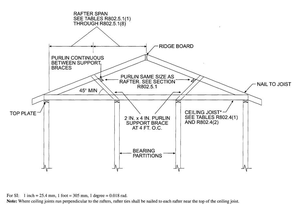
FIGURE R802.5.1
BRACED RAFTER CONSTRUCTION
| BASIC WIND SPEED(mph) (3-second gust) | ROOF SPAN (feet) | OVERHANGSd(pounds⁄foot) | ||||||
|---|---|---|---|---|---|---|---|---|
| 12 | 20 | 24 | 28 | 32 | 36 | 40 | ||
| For SI: 1 inch = 25.4 mm, 1 foot = 305 mm, 1 mph = 0.447 m⁄s, 1 pound⁄foot = 14.5939 N⁄m, 1 pound = 0.454 kg. | ||||||||
| a. The uplift connection requirements are based on a 30 foot mean roof height located in Exposure B. For Exposures C and D and for other mean roof heights, multiply the above loads by the Adjustment Coefficients in Table R301.2(3). | ||||||||
| b. The uplift connection requirements are based on the framing being spaced 24 inches on center. Multiply by 0.67 for framing spaced 16 inches on center and multiply by 0.5 for framing spaced 12 inches on center. | ||||||||
| c. The uplift connection requirements include an allowance for 10 pounds of dead load. | ||||||||
| d. The uplift connection requirements do not account for the effects of overhangs. The magnitude of the above loads shall be increased by adding the overhang loads found in the table. The overhang loads are also based on framing spaced 24 inches on center. The overhang loads given shall be multiplied by the overhang projection and added to the roof uplift value in the table. | ||||||||
| e. The uplift connection requirements are based on wind loading on end zones as defined in Figure 6-2 of ASCE 7. Connection loads for connections located a distance of 20% of the least horizontal dimension of the building from the corner of the building are permitted to be reduced by multiplying the table connection value by 0.7 and multiplying the overhand load by 0.8.v | ||||||||
| f. For wall-to-wall and wall-to-foundation connections, the capacity of the uplift connector is permitted to be reduced by 100 pounds, for each full wall above. (For example, if a 600-pound rated connector is used on the roof framing, a 500-pound rated connector is permitted at the next floor level down). | ||||||||
| 85 | -72 | -120 | -145 | -169 | -193 | -217 | -241 | -38.55 |
| 90 | -91 | -151 | -181 | -212 | -242 | -272 | -302 | -43.22 |
| 100 | -131 | -218 | -262 | -305 | -349 | -393 | -436 | -53.36 |
| 110 | -175 | -292 | -351 | -409 | -467 | -526 | -584 | -64.56 |
R803.1 Lumber sheathing. Allowable spans for lumber used as roof sheathing shall conform to Table R803.1. Spaced lumber sheathing for wood shingle and shake roofing shall conform to the requirements of Sections R905.7 and R905.8. Spaced lumber sheathing is not allowed in Seismic Design Category D2.
| RAFTER OR BEAM SPACING (inches) | MINIMUM NET THICKNESS (inches) |
|---|---|
| For SI: 1 inch =25.4 mm. | |
| a. Minimum 270 Fb’ 340,000 E. | |
| b. Minimum 420 Fb’ 660,000 E. | |
| c. Minimum 600 Fb’ 1,150,000 E. | |
| 24 | 5⁄8 |
| 48a | 1½ T & G |
| 60b | |
| 72c | |
R803.2 Wood structural panel sheathing.
R803.2.1 Identification and grade. Wood structural panels shall conform to DOC PS 1, DOC PS 2 or, when manufactured in Canada, CSA 0437 or CSA 0325, and shall be identified by a grade mark or certificated of inspection issued by an approved agency. Wood structural panels shall comply with the gradesspecified in Table R503.2.1.1(1).
R803.2.1.1 Exposure durability. All wood structural panels, when designed to be permanently exposed in outdoor applications, shall be of an exterior exposure durability. Wood structural panel roof sheathing exposed to the underside may be of interior type bonded with exterior glue, identified as Exposure 1.
R803.2.1.2 Fire-retardant-treated plywood. The allowable unit stresses for fire-retardant-treated plywood, including fastener values, shall be developed from an approved method of investigation that considers the effects of anticipated temperature and humidity to which the fire-retardant-treated plywood will be subjected, the type of treatment and redrying process. The fire-retardant-treated plywood shall be graded by an approved agency.
R803.2.2 Allowable spans. The maximum allowable spans for wood structural panel roof sheathing shall not exceed the values set for in Table R503.2.1.1(1), or APA E30.
R803.2.3 Installation. Wood structural panel used as roof sheathing shall be installed with joints staggered or not staggered in accordance with Table R602.3(1), or APA E30 for wood roof framing or with Table R804.3 for steel roof framing.
R804.1 General. Elements shall be straight and free of any defects that would significantly affected their structural performance. Cold-formed steel roof framing members shall comply with the requirements of this section.
R804.1.1 Applicability limits. The provisions of this section shall control the construction of cold-formed steel roof framing for buildings not greater than 60 feet (18 288 mm) perpendicular to the joist, rafter or truss span, not greater than 40 feet (12 192 mm) in width parallel to the joist span or truss, less than or equal to three stories above grade plane and with roof slopes not less than 3:12 (25-percent slope) or greater than 12:12 (100 percent slope). Cold-formed steel roof framing constructed in accordance with the provisions of this section shall be limited to sites subjected to a maximum design wind speed of 110 miles per hour (49 m⁄s), Exposure B or C, and a maximum ground snow load of 70 pounds per square foot (3350 Pa).
R804.1.2 In-line framing. Cold-formed steel roof framing constructed in accordance with Section R804 shall be located in line with load-bearing studs in accordance with Figure R804.1.2 and the tolerances specified as follows:
R804.2 Structural framing. Load-bearing cold-formed steel roof framing members shall comply with Figure R804.2(1) and with the dimensional and minimum thickness requirements specified in Tables R804.2(1) and R804.2(2). Tracks shall comply with Figure R804.2(2) and shall have a minimum flange width of 1¼ inches (32 mm). The maximum inside bend radius for members shall be the greater of 3⁄32 inch (2.4 mm) minus half the base steel thickness or 1.5 times the base steel thickness.
R804.2.1 Material. Load-bearing cold-formed steel framing members shall be cold-formed to shape from structural quality sheet steel complying with the requirements of one of the following:
R804.2.2 Identification. Load-bearing cold-formed steel framing members shall have a legible label, stencil, stamp or embossment with the following information as a minimum:
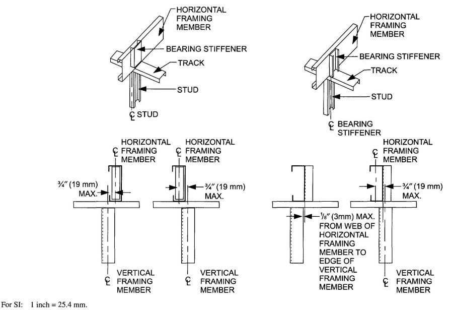
FIGURE R804.1.2
IN-LINE FRAMING
| NOMINAL MEMBER SIZE MEMBER DESIGNATIONa | WEB DEPTH (inches) | MINIMUM FLANGE WIDTH (inches) | MAXIMUM FLANGE WIDTH (inches) | MINIMUM LIP SIZE (inches) |
|---|---|---|---|---|
| For SI: 1 inch = 25.4 mm. | ||||
| a. The member designation is defined by the first number representing the member depth in hundredths of an inch, the letter“s” representing a stud or joist member, the second number representing the flange width in hundredths of an inch, and the letter “t” shall be a number representing the minimum base metal thickness in mils [see table R804.2(2)]. | ||||
| 350S162-t | 3.5 | 1.625 | 2 | 0.5 |
| 550S162-t | 5.5 | 1.625 | 2 | 0.5 |
| 800S162-t | 8 | 1.625 | 2 | 0.5 |
| 1000S162-t | 10 | 1.625 | 2 | 0.5 |
| 1200S162-t | 12 | 1.625 | 2 | 0.5 |
| DESIGNATION THICKNESS (mils) | MINIMUM BASE STEEL THICKNESS (inches) |
|---|---|
| For SI: 1 inch =25.4 mm, 1 mil = 0.0254 mm. | |
| 33 | 0.0329 |
| 43 | 0.0428 |
| 54 | 0.0538 |
| 68 | 0.0677 |
| 97 | 0.0966 |
R804.2.3 Corrosion protection. Load-bearing cold-formed steel framing shall have a metallic coating complying with ASTM A 1003 and one of the following:
R804.2.4 Fastening requirements. Screws for steel-to-steel connections shall be installed with a minimum edge distance and center-to-center spacing of 1½ inch (13 mm), shall be self-drilling tapping, and shall conform to ASTM C 1513. Structural sheathing shall be attached to cold-formed steel roof rafters with minimum No. 8 Self-drilling tapping screws that conform to ASTM C 1513. Screws for attaching structural sheathing to cold-formed steel roof framing shall have a minimum head diameter of 0.292 inch (7.4 mm) with countersunk heads and shall be installed with a minimum edge distance of 3⁄8 inch (10 mm). Gypsum aboard ceilings shall be attached to cold-formed steel joists with minimum No. 6 screws conforming to ASTM C 954 or ASTM C 1513 with a bugle head style and shall be installed in accordance with Section R805. For all connections, screws shall extend through the steel a minimum of three exposed threads. All fasteners shall have rust inhibitive coating suitable for the installation in which they are being used, or be manufactured from material not susceptible to corrosion.
Where No.8 screws are specified in a steel-to-steel connection, reduction of the required number of screws in the connection is permitted in accordance with the reduction factors in Table R804.2.4 when larger screws are used or when one of the sheets of steel being connected is thicker than 33 mils (0.84 mm). When applying the reduction factor, the resulting number of screws shall be rounded up.
| SCREW SIZE | THINNEST CONNECTED STEEL SHEET (mils) | |
|---|---|---|
| 33 | 43 | |
| For SI: 1 mil = 0.0254 mm. | ||
| ≠8 | 1.0 | 0.67 |
| ≠10 | 0.93 | 0.62 |
| ≠12 | 0.86 | 0.56 |
R804.2.5 Web holes, web hole reinforcing and web hole patching. Web holes, web hole reinforcing, and web hole patching shall be in accordance with this section.
R804.2.5.1 Web holes. Web holes in roof framing members shall comply with all of the following conditions:
Framing members with web holes not conforming to the above requirements shall be reinforced in accordance with Section R804.2.5.2, patched in accordance with Section R804.2.5.3 or designed in accordance with accepted engineering practices.
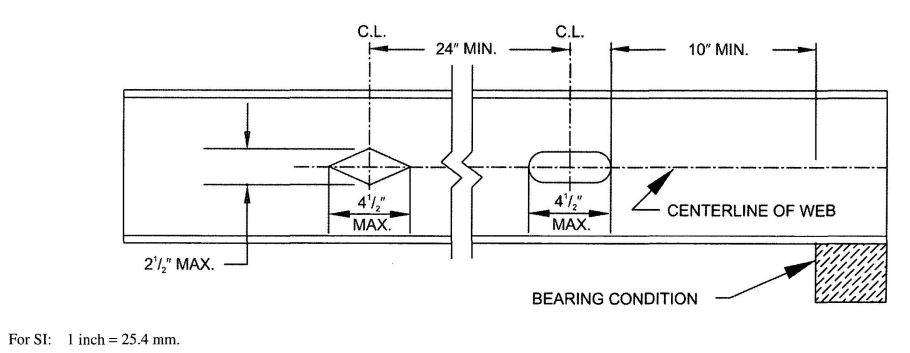
FIGURE R804.2.5.1
WEB HOLES
R804.2.5.2 Web hole reinforcing. Reinforcement of web holes in ceiling joists not conforming to the requirements of Section R804.2.5.1 shall be permitted if the hole is located fully within the center 40 percent of the span and the depth and length of the hole does not exceed 65 percent of the flat width of the web. The reinforcing shall be a steel plate or C-shape section with a hole that does not exceed the web hole size limitations of Section R804.2.5.1 for the member being reinforced. The steel reinforcing shall be the same thickness as the receiving member and shall extend at least 1 inch (25.4 mm) beyond all edges of the hole. The steel reinforcing shall be fastened to the web of the receiving member with No.8 screws spaced no greater than 1 inch (25.4 mm) center-to-center along the edges of the patch with minimum edge distance of 1½ inch (13 mm).
R804.2.5.3 Hole patching. Patching of web holes in roof framing members not conforming to the requirements in Section R804.2.5.1 shall be permitted in accordance with either of the following methods:
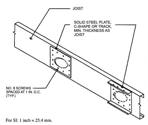
FIGURE R804.2.5.3 WEB HOLE PATCH
R804.3 Roof construction. Cold-formed steel roof systems constructed in accordance with the provisions of this section shall consist of both ceiling joists and rafter in accordance with Figure R804.3 and fastened in accordance with Table R804.3, and hip framing in accordance with Section R804.3.3.
R804.3.1 Ceiling joists. Cold-formed steel ceiling joists shall be in accordance with this section.
R804.3.1.1 Minimum ceiling joist size. Ceiling joist size and thickness shall be determined in accordance with the limits set forth in Tables R804.3.1.1(1) through R804.3.1.1(8). When determining the size of ceiling joists, the lateral support of the top flange shall be classified as or braced, braced at mid-span or braced at third points in accordance with Section R804.3.1.4. Where sheathing material is attached to the top flange of ceiling joists or where the bracing is spaced closer than third
460point of the joists, the “third point” values from Tables R804.3.1.1(1) through R804.3.1.1(8) shall be used.
Ceiling joists shall have a bearing support length of not less than 1½ inches (38 mm) and shall be connected to roof rafters (heel joint) with No. 10 screws in accordance with Figures R804.3.1.1(1) and R804.3.1.1(2) and Table 804.3.1.1(9).
When continuous joists are framed across interior bearing supports, the interior bearing supports shall be located within 24 inches (610 mm) of midspan of the ceiling joist, and the individual spans shall not exceed the applicable spans in Tables R804.3.1.1(2), R804.3.1.1(4), R804.3.1.1(6) and R804.3.1.1(8).
When the attic is to be used as an occupied space, the ceiling joists shall be designed in accordance with Section R505.
R804.3.1.2 Ceiling joist bearing stiffeners. Where required in Tables R804.3.1.1(1) through R804.3.1.1(8), bearing stiffeners shall be installed at each bearing support in accordance with Figure R804.3.1.1(2). Bearing stiffeners shall be fabricated from a C-shaped or track member in accordance with the one of following:
The minimum length of a bearing stiffener shall be the depth of member being stiffened minus 3/8 inch (9.5 mm). Each stiffener shall be fastened to the web of the ceiling joist with a minimum of four No. 8 screws equally spaced as shown in Figure R804.3.1.1(2). Installation of stiffeners shall be permitted on either side of the web.
R804.3.1.3 Ceiling joist bottom flange bracing. The bottom flanges of ceiling joists shall be laterally braced by the application of gypsum board or continuous steel straps installed perpendicular to the joist run in accordance with one of the following:
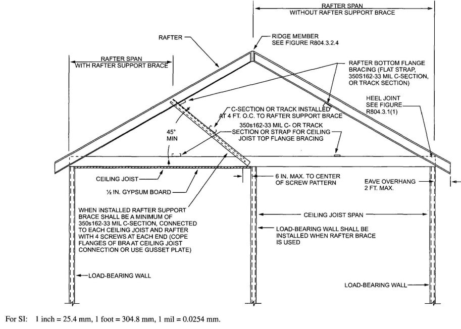
FIGURE R804.3
STEEL ROOF CONSTRUCTION
| DESCRIPTION OF BUILDING ELEMENTS | NUMBER AND SIZE OF FASTENERS | SPACING OF FASTENERS |
|---|---|---|
| For SI: 1 inch=25.4 mm, 1 foot=304.8 mm, 1 pound per square foot=0.0479kPa, 1 mil =0.0254 mm. | ||
| a. Screws shall be applied through the flanges of the truss or ceiling joist or a 54 mil clip angle shall be used with two No. 10 screws in each leg. See Section R804.3.9 for additional requirements to resist uplift forces. | ||
| b. Spacing of fasteners on roof sheathing panel edges applies to panel edges supported by framing members and at all roof plane perimeters. Blocking of roof sheathing panel edges perpendicular to the framing members shall not be required except at the intersection of adjacent roof planes. Roof perimeter shall be supported by framing members or cold-formed blocking of the same depth and gage as the floor members. | ||
| Ceiling joist to top track of load-bearing wall | 2 No. 10 screws | Each joist |
| Roof sheathing (oriented strand board or plywood) to rafters | No. 8 screws | 6″ o.c. on edges and 12″ o.c. at interior supports. 6″ o.c. at gable end truss |
| Truss to bearing walla | 2 No. 10 screws | Each truss |
| Gable end truss to end wall top track | No. 10 screws | 12″ o.c. |
| Rafter to ceiling joist | Minimum No. 10 screws, per Table R804.3.1 | Evently spaced, not less than ½″ from all edges. |
R804.3.1.4 Ceiling joist top flange bracing. The top flanges of ceiling joists shall be laterally braced as required by Tables R804.3.1.1(1) through R804.3.1.1(8), in accordance with one of the following:
Lateral bracing shall be installed perpendicular to the ceiling joists and shall be fastened to the top flange of each joist with one No. 8 screw. Blocking shall be installed between joists in line with bracing at a maximum spacing of 12 feet (3658 mm) measured perpendicular to the joists. Ends of lateral bracing shall be attached to blocking or anchored to a stable building component with two No. 8 screws.
R804.3.1.5 Ceiling joist splicing. Splices in ceiling joists shall be permitted, if ceiling joist splices are supported at interior bearing points and are constructed in accordance with Figure R804.3.1.5. The number of screws on each side of the splice shall be the same as required for the heel joint connection in Table R804.3.1.1(9).
R804.3.2 Roof rafters. Cold-formed steel roof rafters shall be in accordance with this section.
R804.3.2.1 Minimum roof rafter sizes. Roof rafter size and thickness shall be determined in accordance with the limits set forth in Tables R804.3.2.1(1) and R804.3.2.1(2) based on the horizontal projection of the roof rafter span. For determination of roof rafter sizes, reduction of roof spans shall be permitted when a roof rafter support brace is installed in accordance with Section R804.3.2.2. The reduced roof rafter span shall be taken as the larger of the distance from the roof rafter support brace to the ridge or to the heel measured horizontally.
For the purpose of determining roof rafter sizes in Tables R804.3.2.1(1) and R804.3.2.1(2), wind speeds shall be converted to equivalent ground snow loads in accordance with Table R804.3.2.1(3). Roof rafter sizes shall be based on the higher of the ground snow load or the equivalent snow load converted from the wind speed.
R804.3.2.1.1 Eave overhang. Eave overhangs shall not exceed 24 inches (610 mm) measured horizontally.
R804.3.2.1.2 Rake overhangs. Rake overhangs shall not exceed 12 inches (305 mm) measured horizontally. Outlookers at gable endwalls shall be installed in accordance with Figure R804.3.2.1.2.
R804.3.2.2 Roof rafter support brace. When used to reduce roof rafter spans in determining roof rafter sizes, a roof rafter support brace shall meet all of the following conditions:
R804.3.2.3 Roof rafter splice. Roof rafters shall not be spliced.
R804.3.2.4 Roof rafter to ceiling joist and ridge member connection. Roof rafters shall be connected to a parallel ceiling joist to form a continuous tie between exterior walls in accordance with Figures R804.3.1.1(1) or R804.3.1.1(2) and Table R804.3.1.1(9). Ceiling joists shall be connected to the top track of the load-bearing wall in accordance with Table R804.3, either with two No.10 screws applied through the flange of the ceiling joist or by using a 54 mil (1.37 mm) clip angle with two No. 10 screws in each leg. Roof rafters shall be connected to a ridge member with a minimum 2-inch by 2-inch (51 mm by 51 mm) clip angle fastened with No. 10 screws to the ridge member in accordance with Figure R804.3.2.4 and Table R804.3.2.4. The clip angle shall have a steel thickness and shall extend the depth of the roof rafter member to the extent possible. The ridge member shall be fabricated from a C-shaped member and a track section, which shall have a minimum size and steel thickness equivalent to or greater than that of adjacent roof rafters and shall be installed in accordance with Figure R804.3.2.4. The ridge member shall extend the full depth of the sloped roof rafter cut.
R804.3.2.5 Roof rafter bottom flange bracing. The bottom flanges of roof rafters shall be continuously braced, at a maximum spacing of 8 feet (2440 mm) as measured parallel to the roof rafters, with one of the following members:
The bracing element shall be fastened to the bottom flange of each roof rafter with one No.8 screw and shall be fastened to blocking with two No.8 screws. Blocking shall be installed between roof rafters in-line with the continuous bracing at a maximum spacing of 12 feet (3658 mm) measured perpendicular to the roof rafters. The ends of continuous bracing shall be fastened to blocking or anchored to a stable building component with two No.8 screws.
R804.3.3 Hip framing. Hip framing shall consist of jack-rafters, hip members, hip support columns and connections in accordance with this section, or shall be in accordance with an approved design. The provisions of this section for hip members and hip support columns shall apply only where the jack rafter slope is greater than or equal to the roof slope. For the purposes of determining member sizes in this sections, wind speeds shall be converted to equivalent ground snow load in accordance with Table R804.3.2.1(3).
R804.3.3.1 Jack rafters. Jack rafters shall meet the requirements for roof rafters in accordance with Section R804.3.2, except that the requirements in Section R804.3.2.4 shall not apply.
R804.3.3.2 Hip members. Hip members shall be fabricated from C-shape members and track section, which shall have minimum sizes determined in accordance with Table R804.3.3.2. The C-shape member and track section shall be connected at a maximum spacing of 24 inches (610 mm) using No. 10 screws through top and bottom flanges in accordance with Figure R804.3.2.4. The depth of the hip member shall match that of the roof rafters and jack rafters, or shall be based on an approved design for a beam pocket at the corner of the supporting wall.
R804.3.3.3 Hip support columns. Hip support columns shall be used to support hip members at the ridge. A hip support column shall consist of a pair of C-shape members, with a minimum size determined in accordance with Table R804.3.3.3. The C-shape members shall be connected at a maximum spacing of 24 inches (610 mm) on center to form a box using minimum 3-inch (76 mm) x 33-mil (0.84 mm) strap connected to each of the flanges of the C-shape members with three-No. 10 screws. Hip support columns shall have a continuous load path to the foundation and shall be supported at the ceiling line by an interior wall or by an approved design for a supporting element.
R804.3.3.4 Hip framing connections. Hip rafter framing connections shall be installed in accordance with the following:
| MEMBER DESIGNATION | ALLOWABLE SPAN (feet-inches) | |||||
|---|---|---|---|---|---|---|
| Lateral Support of Top (Compression) Flange | ||||||
| Unbraced | Mid-Span Bracing | Third-Point Bracing | ||||
| Ceiling Joist Spacing (inches) | ||||||
| 16 | 24 | 16 | 24 | 16 | 24 | |
| For SI: 1 inch=25.4 mm, 1 foot=304.8 mm, 1 pound per square foot=0.0479 kPa. | ||||||
| a. Deflection criterion: L/240 for total loads. | ||||||
| b. Ceiling dead load=5 psf. | ||||||
| c. Bearing stiffeners are required at all bearing points and concentrated load locations. | ||||||
| 350S162-33 | 9′;-5″ | 8′;-6″ | 12′;-2″ | 10′;-4″ | 12′;-2″ | 10′;-7″ |
| 350S162-43 | 10′;-3″ | 9′;-2″ | 12′;-10″ | 11′;-2″ | 12′;-10″ | 11′;-12″ |
| 350S162-54 | 11′;-1″ | 9′;-11″ | 13′;-9″ | 12′;-0″ | 13′;-9″ | 12′;-0″ |
| 350S162-68 | 12′;-1″ | 10′;-9″ | 14′;-8″ | 12′;-10″ | 14′;-8″ | 12′;-10″ |
| 350S162-97 | 14′;-4″ | 12′;-7″ | 16′;-4″ | 14′;-3″ | 16′;-4″ | 14′;-3″ |
| 550S162-33 | 10′;-7″ | 9′;-6″ | 14′;-10″ | 12′;-10″ | 15′;-11″ | 13′;-4″ |
| 550S162-43 | 11′;-8″ | 10′;-6″ | 16′;-4″ | 14′;-3″ | 17′;-10″ | 15′;-3″ |
| 550S162-54 | 12′;-6″ | 11′;-2″ | 17′;-7″ | 15′;-7″ | 19′;-5″ | 16′;-10″ |
| 550S162-68 | 13′;-6″ | 12′;-1″ | 19′;-2″ | 17′;-1″ | 21′;-0″ | 18′;-4″ |
| 550S162-97 | 15′;-9″ | 13′;-11″ | 21′;-8″ | 19′;-3″ | 23′;-5″ | 20′;-5″ |
| 800S162-33 | 12′;-2″ | 10′;-11″ | 17′;-8″ | 15′;-10″ | 19′;-10″ | 17′;-1″ |
| 800S162-43 | 13′;-0″ | 11′;-9″ | 18′;-10″ | 17′;-0″ | 21′;-6″ | 19′;-1″ |
| 800S162-54 | 13′;-10″ | 12′;-5″ | 20′;-0″ | 18′;-0″ | 22′;-9″ | 20′;-4″ |
| 800S162-68 | 14′;-11″ | 13′;-4″ | 21′;-3″ | 19′;-1″ | 24′;-1″ | 21′;-8″ |
| 800S162-97 | 17′;-1″ | 15′;-2″ | 23′;-10″ | 21′;-3″ | 26′;-7″ | 23′;-10″ |
| 1000S162-43 | 13′;-11″ | 12′;-6″ | 20′;-2″ | 18′;-3″ | 23′;-1″ | 20′;-9″ |
| 1000S162-54 | 14′;-9″ | 13′;-3″ | 21′;-4″ | 19′;-3″ | 24′;-4″ | 22′;-0″ |
| 1000S162-68 | 15′;-10″ | 14′;-2″ | 22′;-8″ | 20′;-5″ | 25′;-9″ | 23′;-2″ |
| 1000S162-97 | 18′;-0″ | 16′;-0″ | 25′;-3″ | 22′;-7″ | 28′;-3″ | 25′;-4″ |
| 1200S162-43 | 14′;-8″ | 13′;-3″ | 21′;-4″ | 19′;-3″ | 24′;-5″ | 21′;-8″ |
| 1200S162-54 | 15′;-7″ | 14′;-0″ | 22′;-6″ | 20′;-4″ | 25′;-9″ | 23′;-2″ |
| 1200S162-68 | 16′;-8″ | 14′;-11″ | 23′;-11″ | 21′;-6″ | 27′;-2″ | 24′;-6″ |
| 1000S162-97 | 18′;-9″ | 16′;-9″ | 26′;-6″ | 23′;-8″ | 29′;-9″ | 26′;-9″ |
| MEMBER DESIGNATION | ALLOWABLE SPAN (feet-inches) | |||||
|---|---|---|---|---|---|---|
| Lateral Support of Top (Compression) Flange | ||||||
| Unbraced | Mid-Span Bracing | Third-Point Bracing | ||||
| Ceiling Joist Spacing (inches) | ||||||
| 16 | 24 | 16 | 24 | 16 | 24 | |
| For SI: 1 inch = 25.4 mm, 1 foot = 304.8 mm, 1 pound per square foot = 0.0479 kPa. | ||||||
| a. Deflection criterion: L/240 for total loads. | ||||||
| b. Ceiling dead load = 5 psf. | ||||||
| c. Bearing stiffeners are required at all bearing points and concentrated load locations. | ||||||
| 350S162-33 | 12′;-11″ | 10′;-11″ | 13′;-5″ | 10′;-11″ | 13′;-5″ | 10′;-11″ |
| 350S162-43 | 14′;-2″ | 12′;-8″ | 15′;-10″ | 12′;-11″ | 15′;-10″ | 12′;-11″ |
| 350S162-54 | 15′;-6″ | 13′;-10″ | 17′;-1″ | 14′;-6″ | 17′;-9″ | 14′;-6″ |
| 350S162-68 | 17′;-3″ | 15′;-3″ | 18′;-6″ | 16′;-1″ | 19′;-8″ | 16′;-1″ |
| 350S162-97 | 20′;-10″ | 18′;-4″ | 21′;-5″ | 18′;-10″ | 21′;-11″ | 18′;-10″ |
| 550S162-33 | 14′;-4″ | 12′;-11″ | 16′;-7″ | 14′;-1″ | 17′;-3″ | 14′;-1″ |
| 550S162-43 | 16′;-0″ | 14′;-1″ | 17′;-11″ | 16′;-1″ | 20′;-7″ | 16′;-10″ |
| 550S162-54 | 17′;-4″ | 15′;-6″ | 19′;-5″ | 17′;-6″ | 23′;-2″ | 19′;-0″ |
| 550S162-68 | 19′;-1″ | 16′;-11″ | 20′;-10″ | 18′;-8″ | 25′;-2″ | 21′;-5″ |
| 550S162-97 | 22′;-8″ | 19′;-9″ | 23′;-6″ | 20′;-11″ | 27′;-11″ | 25′;-1″ |
| 800S162-33 | 16′;-5″ | 14′;-10″ | 19′;-2″ | 17′;-3″ | 23′;-1″ | 18′;-3″ |
| 800S162-43 | 17′;-9″ | 15′;-11″ | 20′;-6″ | 18′;-5″ | 25′;-0″ | 22′;-6″ |
| 800S162-54 | 19′;-1″ | 17′;-1″ | 21′;-8″ | 19′;-6″ | 26′;-4″ | 23′;-9″ |
| 800S162-68 | 20′;-9″ | 18′;-6″ | 23′;-1″ | 20′;-9″ | 28′;-0″ | 25′;-2″ |
| 800S162-97 | 24′;-5″ | 21′;-6″ | 26′;-0″ | 23′;-2″ | 31′;-1″ | 27′;-9″ |
| 1000S162-43 | 18′;-11″ | 17′;-0″ | 21′;-11″ | 19′;-9″ | 26′;-8″ | 24′;-1″ |
| 1000S162-54 | 20′;-3″ | 18′;-2″ | 23′;-2″ | 20′;-10″ | 28′;-2″ | 25′;-5″ |
| 1000S162-68 | 21′;-11″ | 19′;-7″ | 24′;-7″ | 22′;-2″ | 29′;-10″ | 26′;-11″ |
| 1000S162-97 | 25′;-7″ | 22′;-7″ | 27′;-6″ | 24′;-6″ | 33′;-0″ | 29′;-7″ |
| 1200S162-43 | 19′;-11″ | 17′;-11″ | 23′;-1″ | 20′;-10″ | 28′;-3″ | 25′;-6″ |
| 1200S162-54 | 21′;-3″ | 19′;-1″ | 24′;-5″ | 22′;-0″ | 29′;-9″ | 26′;-10″ |
| 1200S162-68 | 23′;-0″ | 20′;-7″ | 25′;-11″ | 23′;-4″ | 31′;-6″ | 28′;-4″ |
| 1000S162-97 | 26′;-7″ | 23′;-6″ | 28′;-9″ | 25′;-10″ | 34′;-8″ | 31′;-1″ |
| MEMBER DESIGNATION | ALLOWABLE SPAN (feet-inches) | |||||
|---|---|---|---|---|---|---|
| Lateral Support of Top (Compression) Flange | ||||||
| Unbraced | Mid-Span Bracing | Third-Point Bracing | ||||
| Ceiling Joist Spacing (inches) | ||||||
| 16 | 24 | 16 | 24 | 16 | 24 | |
| For SI: 1 inch=25.4 mm, 1 foot =304.8 mm, 1 pound per square foot = 0.0479 kPa. | ||||||
| a. Deflection criterion: L/240 for total loads. | ||||||
| b. Ceiling dead load = 5 psf. | ||||||
| c. Bearing stiffeners are required at all bearing points and concentrated load locations. | ||||||
| 350S162-33 | 8′;-2″ | 7′;-2″ | 9′;-9″ | 8′;-1″ | 9′;-11″ | 8′;-1″ |
| 350S162-43 | 8′;-10″ | 7′;-10″ | 11′;-0″ | 9′;-5″ | 11′;-0″ | 9′;-7″ |
| 350S162-54 | 9′;-6″ | 8′;-6″ | 11′;-9″ | 10′;-3″ | 11′;-9″ | 10′;-3″ |
| 350S162-68 | 10′;-4″ | 9′;-2″ | 12′;-7″ | 11′;-0″ | 12′;-7″ | 11′;-0″ |
| 350S162-97 | 12′;-1″ | 10′;-8″ | 14′;-0″ | 12′;-0″ | 14′;-0″ | 12′;-0″ |
| 550S162-33 | 9′;-2″ | 8′;-3″ | 12′;-2″ | 10′;-2″ | 12′;-6″ | 10′;-5″ |
| 550S162-43 | 10′;-1″ | 9′;-1″ | 13′;-7″ | 11′;-7″ | 14′;-5″ | 12′;-2″ |
| 550S162-54 | 10′;-9″ | 9′;-8″ | 14′;-10″ | 12′;-10″ | 15′;-11″ | 13′;-6″ |
| 550S162-68 | 11′;-7″ | 10′;-4″ | 16′;-4″ | 14′;-0″ | 17′;-5″ | 14′;-11″ |
| 550S162-97 | 13′;-4″ | 11′;-10″ | 18′;-5″ | 16′;-2″ | 20′;-1″ | 17′;-1″ |
| 800S162-33 | 10′;-7″ | 9′;-6″ | 15′;-1″ | 13′;-0″ | 16′;-2″ | 13′;-7″ |
| 800S162-43 | 11′;-4″ | 10′;-2″ | 16′;-5″ | 14′;-6″ | 18′;-2″ | 15′;-9″ |
| 800S162-54 | 12′;-0″ | 10′;-9″ | 17′;-4″ | 15′;-6″ | 19′;-6″ | 17′;-0″ |
| 800S162-68 | 12′;-10″ | 11′;-6″ | 18′;-5″ | 16′;-6″ | 20′;-10″ | 18′;-3″ |
| 800S162-97 | 14′;-7″ | 12′;-11″ | 20′;-5″ | 18′;-3″ | 22′;-11″ | 20′;-5″ |
| 1000S162-43 | 12′;-1″ | 10′;-11″ | 17′;-7″ | 15′;-10″ | 19′;-11″ | 17′;-3″ |
| 1000S162-54 | 12′;-10″ | 11′;-6″ | 18′;-7″ | 16′;-9″ | 21′;-2″ | 18′;-10″ |
| 1000S162-68 | 13′;-8″ | 12′;-3″ | 19′;-8″ | 17′;-8″ | 22′;-4″ | 20′;-1″ |
| 1000S162-97 | 15′;-4″ | 13′;-8″ | 21′;-8″ | 19′;-5″ | 24′;-5″ | 21′;-11″ |
| 1200S162-43 | 12′;-9″ | 11′;-6″ | 18′;-7″ | 16′;-6″ | 20′;-9″ | 18′;-2″ |
| 1200S162-54 | 13′;-6″ | 12′;-2″ | 19′;-7″ | 17′;-8″ | 22′;-5″ | 20′;-2″ |
| 1200S162-68 | 14′;-4″ | 12′;-11″ | 20′;-9″ | 18′;-8″ | 23′;-7″ | 21′;-3″ |
| 1200S162-97 | 16′;-1″ | 14′;-4″ | 22′;-10″ | 20′;-6″ | 25′;-9″ | 23′;-2″ |
| MEMBER DESIGNATION | ALLOWABLE SPAN (feet-inches) | |||||
|---|---|---|---|---|---|---|
| Lateral Support of Top (Compression) Flange | ||||||
| Unbraced | Mid-Span Bracing | Third-Point Bracing | ||||
| Ceiling Joist Spacing (inches) | ||||||
| 16 | 24 | 16 | 24 | 16 | 24 | |
| For SI: 1 inch = 25.4 mm, 1 foot = 304.8 mm, 1 pound per square foot = 0.0479 kPa. | ||||||
| a. Deflection critertion: L/240 for total loads. | ||||||
| b. Ceiling dead load = 5 psf. | ||||||
| c. Bearing stiffeners are required at all bearing points and concentrated load locations. | ||||||
| 350S162-33 | 10′;-2″ | 8′;-4″ | 10′;-2″ | 8′;-4″ | 10′;-2″ | 8′;-4″ |
| 350S162-43 | 12′;-1″ | 9′;-10″ | 12′;-1″ | 9′;-10″ | 12′;-1″ | 9′;-10″ |
| 350S162-54 | 13′;-3″ | 11′;-0″ | 13′;-6″ | 11′;-0″ | 13′;-6″ | 11′;-0″ |
| 350S162-68 | 14′;-7″ | 12′;-3″ | 15′;-0″ | 12′;-3″ | 15′;-0″ | 12′;-3″ |
| 350S162-97 | 17′;-6″ | 14′;-3″ | 17′;-6″ | 14′;-3″ | 17′;-6″ | 14′;-3″ |
| 550S162-33 | 12′;-5″ | 10′;-9″ | 13′;-2″ | 10′;-9″ | 13′;-2″ | 10′;-9″ |
| 550S162-43 | 13′;-7″ | 12′;-1″ | 15′;-6″ | 12′;-9″ | 15′;-8″ | 12′;-9″ |
| 550S162-54 | 14′;-11″ | 13′;-4″ | 16′;-10″ | 14′;-5″ | 17′;-9″ | 14′;-5″ |
| 550S162-68 | 16′;-3″ | 14′;-5″ | 18′;-0″ | 16′;-1″ | 20′;-0″ | 16′;-4″ |
| 550S162-97 | 19′;-1″ | 16′;-10″ | 20′;-3″ | 18′;-0″ | 23′;-10″ | 19′;-5″ |
| 800S162-33 | 14′;-3″ | 12′;-4″ | 16′;-7″ | 12′;-4″ | 16′;-7″ | 12′;-4″ |
| 800S162-43 | 15′;-4″ | 13′;-10″ | 17′;-9″ | 16′;-0″ | 21′;-8″ | 17′;-9″ |
| 800S162-54 | 16′;-5″ | 14′;-9″ | 18′;-10″ | 16′;-11″ | 22′;-11″ | 20′;-6″ |
| 800S162-68 | 17′;-9″ | 15′;-11″ | 20′;-0″ | 18′;-0″ | 24′;-3″ | 21′;-10″ |
| 800S162-97 | 20′;-8″ | 18′;-3″ | 22′;-3″ | 19′;-11″ | 26′;-9″ | 24′;-0″ |
| 1000S162-43 | 16′;-5″ | 14′;-9″ | 19′;-0″ | 17′;-2″ | 23′;-3″ | 18′;-11″ |
| 1000S162-54 | 17′;-6″ | 15′;-8″ | 20′;-1″ | 18′;-1″ | 24′;-6″ | 22′;-1″ |
| 1000S162-68 | 18′;-10″ | 16′;-10″ | 21′;-4″ | 19′;-2″ | 25′;-11″ | 23′;-4″ |
| 1000S162-97 | 21′;-8″ | 19′;-3″ | 23′;-7″ | 21′;-2″ | 28′;-5″ | 25′;-6″ |
| 1200S162-43 | 17′;-3″ | 15′;-7″ | 20′;-1″ | 18′;-2″ | 24′;-6″ | 18′;-3″ |
| 1200S162-54 | 18′;-5″ | 16′;-6″ | 21′;-3″ | 19′;-2″ | 25′;-11″ | 23′;-5″ |
| 1200S162-68 | 19′;-9″ | 17′;-8″ | 22′;-6″ | 20′;-3″ | 27′;-4″ | 24′;-8″ |
| 1200S162-97 | 22′;-7″ | 20′;-1″ | 24′;-10″ | 22′;-3″ | 29′;-11″ | 26′;-11″ |
| MEMBER DESIGNATION | ALLOWABLE SPAN (feet-inches) | |||||
|---|---|---|---|---|---|---|
| Lateral Support of Top (Compression) Flange | ||||||
| Unbraced | Mid-Span Bracing | Third-Point Bracing | ||||
| Ceiling Joist Spacing (inches) | ||||||
| 16 | 24 | 16 | 24 | 16 | 24 | |
| For SI: 1 inch = 25.4 mm, 1 foot = 304.8 mm, 1 pound per square foot = 0.0479 kPa. | ||||||
| a. Deflection criterion: L/240 for total loads. | ||||||
| b. Ceiling dead load = 5 psf. | ||||||
| 350S162-33 | 9′;-5″ | 8′;-6″ | 12′;-2″ | 10′;-4″ | 12′;-2″ | 10′;-7″ |
| 350S162-43 | 10′;-3″ | 9′;-12″ | 13′;-2″ | 11′;-6″ | 13′;-2″ | 11′;-6″ |
| 350S162-54 | 11′;-1″ | 9′;-11″ | 13′;-9″ | 12′;-0″ | 13′;-9″ | 12′;-0″ |
| 350S162-68 | 12′;-1″ | 10′;-9″ | 14′;-8″ | 12′;-10″ | 14′;-8″ | 12′;-10″ |
| 350S162-97 | 14′;-4″ | 12′;-7″ | 16′;-10″ | 14′;-3″ | 16′;-4″ | 14′;-3″ |
| 550S162-33 | 10′;-7″ | 9′;-6″ | 14′;-10″ | 12′;-10″ | 15′;-11″ | 13′;-4″ |
| 550S162-43 | 11′;-8″ | 10′;-6″ | 16′;-4″ | 14′;-3″ | 17′;-10″ | 15′;-3″ |
| 550S162-54 | 12′;-6″ | 11′;-2″ | 17′;-7″ | 15′;-7″ | 19′;-5″ | 16′;-10″ |
| 550S162-68 | 13′;-6″ | 12′;-1″ | 19′;-2″ | 17′;-0″ | 21′;-0″ | 18′;-4″ |
| 550S162-97 | 15′;-9″ | 13′;-11″ | 21′;-8″ | 19′;-3″ | 23′;-5″ | 20′;-5″ |
| 800S162-33 | — | — | — | — | — | — |
| 800S162-43 | 13′;-0″ | 11′;-9″ | 18′;-10″ | 17′;-0″ | 21′;-6″ | 19′;-0″ |
| 800S162-54 | 13′;-10″ | 12′;-5″ | 20′;-0″ | 18′;-0″ | 22′;-9″ | 20′;-4″ |
| 800S162-68 | 14′;-11″ | 13′;-4″ | 21′;-3″ | 19′;-1″ | 24′;-1″ | 21′;-8″ |
| 800S162-97 | 17′;-1″ | 15′;-2″ | 23′;-10″ | 21′;-3″ | 26′;-7″ | 23′;-10″ |
| 1000S162-43 | — | — | — | — | — | — |
| 1000S162-54 | 14′;-9″ | 13′;-3″ | 21′;-4″ | 19′;-3″ | 24′;-4″ | 22′;-0″ |
| 1000S162-68 | 15′;-10″ | 14′;-2″ | 22′;-8″ | 20′;-5″ | 25′;-9″ | 23′;-2″ |
| 1000S162-97 | 18′;-0″ | 16′;-0″ | 25′;-3″ | 22′;-7″ | 28′;-3″ | 25′;-4″ |
| 1200S162-43 | — | — | — | — | — | — |
| 1200S162-54 | — | — | — | — | — | — |
| 1200S162-68 | 16′;-8″ | 14′;-11″ | 23′;-11″ | 21′;-6″ | 27′;-2″ | 24′;-6″ |
| 1000S162-97 | 18′;-9″ | 16′;-9″ | 26′;-6″ | 23′;-8″ | 29′;-9″ | 26′;-9″ |
| MEMBER DESIGNATION | ALLOWABLE SPAN (feet-inches) | |||||
|---|---|---|---|---|---|---|
| Lateral Support of Top (Compression) Flange | ||||||
| Unbraced | Mid-Span Bracing | Third-Point Bracing | ||||
| Ceiling Joist Spacing (inches) | ||||||
| 16 | 24 | 16 | 24 | 16 | 24 | |
| For SI: 1 inch = 25.4 mm, 1 foot = 304.8 mm, 1 pound per square foot = 0.0479 kPa. | ||||||
| a. Deflection criterion: L/240 for total loads. | ||||||
| b. Ceiling dead load = 5 psf. | ||||||
| 350S162-33 | 11′;-9″ | 8′;-11″ | 11′;-9″ | 8′;-11″ | 11′;-9″ | 8′;-11″ |
| 350S162-43 | 14′;-2″ | 11′;-7″ | 14′;-11″ | 11′;-7″ | 14′;-11″ | 11′;-7″ |
| 350S162-54 | 15′;-6″ | 13′;-10″ | 17′;-1″ | 13′;-10″ | 17′;-7″ | 13′;-10″ |
| 350S162-68 | 17′;-3″ | 15′;-3″ | 18′;-6″ | 16′;-1″ | 19′;-8″ | 16′;-1″ |
| 350S162-97 | 20′;-10″ | 18′;-4″ | 21′;-5″ | 18′;-9″ | 21′;-11″ | 18′;-9″ |
| 550S162-33 | 13′;-4″ | 9′;-11″ | 13′;-4″ | 9′;-11″ | 13′;-4″ | 9′;-11″ |
| 550S162-43 | 16′;-0″ | 13′;-6″ | 17′;-9″ | 13′;-6″ | 17′;-9″ | 13′;-6″ |
| 550S162-54 | 17′;-4″ | 15′;-6″ | 19′;-5″ | 16′;-10″ | 21′;-9″ | 16′;-10″ |
| 550S162-68 | 19′;-1″ | 16′;-11″ | 20′;-10″ | 18′;-8″ | 24′;-11″ | 20′;-6″ |
| 550S162-97 | 22′;-8″ | 20′;-0″ | 23′;-9″ | 21′;-1″ | 28′;-2″ | 25′;-1″ |
| 800S162-33 | — | — | — | — | — | — |
| 800S162-43 | 17′;-9″ | 15′;-7″ | 20′;-6″ | 15′;-7″ | 21′;-0″ | 15′;-7″ |
| 800S162-54 | 19′;-1″ | 17′;-1″ | 21′;-8″ | 19′;-6″ | 26′;-4″ | 23′;-10″ |
| 800S162-68 | 20′;-9″ | 18′;-6″ | 23′;-1″ | 20′;-9″ | 28′;-0″ | 25′;-2″ |
| 800S162-97 | 24′;-5″ | 21′;-6″ | 26′;-0″ | 23′;-2″ | 31′;-1″ | 27′;-9″ |
| 1000S162-43 | — | — | — | — | — | — |
| 1000S162-54 | 20′;-3″ | 18′;-2″ | 23′;-2″ | 20′;-10″ | 28′;-2″ | 21′;-2″ |
| 1000S162-68 | 21′;-11″ | 19′;-7″ | 24′;-7″ | 22′;-2″ | 29′;-10″ | 26′;-11″ |
| 1000S162-97 | 25′;-7″ | 22′;-7″ | 27′;-6″ | 24′;-6″ | 33′;-0″ | 29′;-7″ |
| 1200S162-43 | — | — | — | — | — | — |
| 1200S162-54 | — | — | — | — | — | — |
| 1200S162-68 | 23′;-0″ | 20′;-7″ | 25′;-11″ | 23′;-4″ | 31′;-6″ | 28′;-4″ |
| 1200S162-97 | 26′;-7″ | 23′;-6″ | 28′;-9″ | 25′;-10″ | 34′;-8″ | 31′;-1″ |
| MEMBER DESIGNATION | ALLOWABLE SPAN (feet-inches) | |||||
|---|---|---|---|---|---|---|
| Lateral Support of Top (Compression) Flange | ||||||
| Unbraced | Mid-Span Bracing | Third-Point Bracing | ||||
| Ceiling Joist Spacing (inches) | ||||||
| 16 | 24 | 16 | 24 | 16 | 24 | |
| For SI: 1 inch = 25.4 mm, 1 foot = 304.8 mm, 1 pound per square foot = 0.0479 kPa. | ||||||
| a. Deflection criterion: L/240 for total loads. | ||||||
| b. Ceiling dead load = 5 psf. | ||||||
| 350S162-33 | 8′;-2″ | 6′;-10″ | 9′;-9″ | 6′;-10″ | 9′;-11″ | 6′;-10″ |
| 350S162-43 | 8′;-10″ | 7′;-10 | 11′;-0″ | 9′;-5″ | 11′;-0″ | 9′;-7″ |
| 350S162-54 | 9′;-6″ | 8′;-6″ | 11′;-9″ | 10′;-3″ | 11′;-9″ | 10′;-3″ |
| 350S162-68 | 10′;-4″ | 9′;-2″ | 12′;-7″ | 11′;-0″ | 12′;-7″ | 11′;-0″ |
| 350S162-97 | 12′;-10″ | 10′;-8″ | 13′;-9″ | 12′;-0″ | 13′;-9″ | 12′;-0″ |
| 550S162-33 | 9′;-2″ | 8′;-3″ | 12′;-2″ | 8′;-5″ | 12′;-6″ | 8′;-5″ |
| 550S162-43 | 10′;-1″ | 9′;-1″ | 13′;-7″ | 11′;-8″ | 14′;-5″ | 12′;-2″ |
| 550S162-54 | 10′;-9″ | 9′;-8″ | 14′;-10″ | 12′;-10″ | 15′;-11″ | 13′;-6″ |
| 550S162-68 | 11′;-7″ | 10′;-4″ | 16′;-4″ | 14′;-0″ | 17′;-5″ | 14′;-11″ |
| 550S162-97 | 13′;-4″ | 11′;-10″ | 18′;-5″ | 16′;-2″ | 20′;-1″ | 17′;-4″ |
| 800S162-33 | — | — | — | — | — | — |
| 800S162-43 | 11′;-4″ | 10′;-1″ | 16′;-5″ | 13′;-6″ | 18′;-1″ | 13′;-6″ |
| 800S162-54 | 20′;-0″ | 10′;-9″ | 17′;-4″ | 15′;-6″ | 19′;-6″ | 27′;-0″ |
| 800S162-68 | 12′;-10″ | 11′;-6″ | 18′;-5″ | 16′;-6″ | 20′;-10″ | 18′;-3″ |
| 800S162-97 | 14′;-7″ | 12′;-11″ | 20′;-5″ | 18′;-3″ | 22′;-11″ | 20′;-5″ |
| 1000S162-43 | — | — | — | — | — | — |
| 1000S162-54 | 12′;-10″ | 11′;-6″ | 18′;-7″ | 16′;-9″ | 21′;-2″ | 15′;-5″ |
| 1000S162-68 | 13′;-8″ | 12′;-3″ | 19′;-8″ | 17′;-8″ | 22′;-4″ | 20′;-1″ |
| 1000S162-97 | 15′;-4″ | 13′;-8″ | 21′;-8″ | 19′;-5″ | 24′;-5″ | 21′;-11″ |
| 1200S162-43 | — | — | — | — | — | — |
| 1200S162-54 | — | — | — | — | — | — |
| 1200S162-68 | 14′;-4″ | 12′;-11″ | 20′;-9″ | 18′;-8″ | 23′;-7″ | 21′;-3″ |
| 1000S162-97 | 16′;-1″ | 14′;-4″ | 22′;-10″ | 20′;-6″ | 25′;-9″ | 23′;-2″ |
| MEMBER DESIGNATION | ||||||
|---|---|---|---|---|---|---|
| ALLOWABLE SPAN (feet-inches) | ||||||
| Lateral Support of Top (Compression) Flange | ||||||
| Unbraced | Mid-Span Bracing | Third-Point Bracing | ||||
| Ceiling Joist Spacing (inches) | ||||||
| 16 | 24 | 16 | 24 | 16 | 24 | |
| For SI: 1 inch = 25.4 mm, 1 foot = 304.8 mm, 1 pound per square foot = 0.0479 kPa. | ||||||
| a. Deflection criterion: L/240 for total loads. | ||||||
| b. Ceiling dead load = 5 psf. | ||||||
| 350S162-33 | 8′;-1″ | 6′;-1″ | 8′;-1″ | 6′;-1″ | 8′;-1″ | 6′;-1″ |
| 350S162-43 | 10′;-7″ | 8′;-1″ | 10′;-7″ | 8′;-1″ | 10′;-7″ | 8′;-1″ |
| 350S162-54 | 12′;-8″ | 9′;-10″ | 12′;-8″ | 9′;-10″ | 12′;-8″ | 9′;-10″ |
| 350S162-68 | 14′;-7″ | 11′;-10″ | 14′;-11″ | 11′;-10″ | 14′;-11″ | 11′;-10″ |
| 350S162-97 | 17′;-6″ | 14′;-3″ | 17′;-6″ | 14′;-3″ | 17′;-6″ | 14′;-3″ |
| 550S162-33 | 8′;-11″ | 6′;-8″ | 8′;-11″ | 6′;-8″ | 8′;-11″ | 6′;-8″ |
| 550S162-43 | 12′;-3″ | 9′;-2″ | 12′;-3″ | 9′;-2″ | 12′;-3″ | 9′;-2″ |
| 550S162-54 | 14′;-11″ | 11′;-8″ | 15′;-4″ | 11′;-8″ | 15′;-4″ | 11′;-8″ |
| 550S162-68 | 16′;-3″ | 14′;-5″ | 18′;-0″ | 15′;-8″ | 18′;-10″ | 14′;-7″ |
| 550S162-97 | 19′;-1″ | 16′;-10″ | 20′;-3″ | 18′;-0″ | 23′;-9″ | 19′;-5″ |
| 800S162-33 | — | — | — | — | — | — |
| 800S162-43 | 13′;-11″ | 9′;-10″ | 13′;-11″ | 9′;-10″ | 13′;-11″ | 9′;-10″ |
| 800S162-54 | 16′;-5″ | 13′;-9″ | 18′;-8″ | 13′;-9″ | 18′;-8″ | 13′;-9″ |
| 800S162-68 | 17′;-9″ | 15′;-11″ | 20′;-0″ | 18′;-0″ | 24′;-1″ | 18′;-3″ |
| 800S162-97 | 20′;-8″ | 18′;-3″ | 22′;-3″ | 19′;-11″ | 26′;-9″ | 24′;-0″ |
| 1000S162-43 | — | — | — | — | — | — |
| 1000S162-54 | 17′;-6″ | 13′;-11″ | 19′;-1″ | 13′;-11″ | 19′;-1″ | 13′;-11″ |
| 1000S162-68 | 18′;-10″ | 16′;-10″ | 21′;-4″ | 19′;-2″ | 25′;-11″ | 19′;-7″ |
| 1000S162-97 | 21′;-8″ | 19′;-3″ | 23′;-7″ | 21′;-2″ | 28′;-5″ | 25′;-6″ |
| 1200S162-43 | — | — | — | — | — | — |
| 1200S162-54 | — | — | — | — | — | — |
| 1200S162-68 | 19′;-9″ | 17′;-8″ | 22′;-6″ | 19′;-8″ | 26′;-8″ | 19′;-8″ |
| 1200S162-97 | 22′;-7″ | 20′;-1″ | 24′;-10″ | 22′;-3″ | 29′;-11″ | 26′;-11″ |
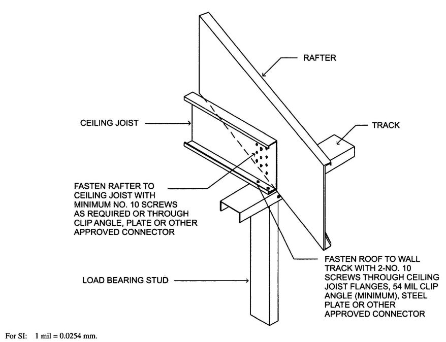
FIGURE R804.3.1.1(1)
JOIST TO RAFTER CONNECTION
| ROOF SLOPE | ||||||||||||||||||||
|---|---|---|---|---|---|---|---|---|---|---|---|---|---|---|---|---|---|---|---|---|
| NUMBER OF SCREWS | ||||||||||||||||||||
| Building width (feet) | ||||||||||||||||||||
| 24 | 28 | 32 | 36 | 40 | ||||||||||||||||
| Ground snow load (psf) | ||||||||||||||||||||
| 20 | 30 | 50 | 70 | 20 | 30 | 50 | 70 | 20 | 30 | 50 | 70 | 20 | 30 | 50 | 70 | 20 | 30 | 50 | 70 | |
| For SI: 1 inch = 25.4 mm, 1 foot = 304.8 mm, 1 pound per square foot = 0.0479kPa. | ||||||||||||||||||||
| a. Screws shall be No. 10. | ||||||||||||||||||||
| 3/12 | 5 | 6 | 9 | 11 | 5 | 7 | 10 | 13 | 6 | 8 | 11 | 15 | 7 | 8 | 13 | 17 | 8 | 9 | 14 | 19 |
| 4/12 | 4 | 5 | 7 | 9 | 4 | 5 | 8 | 10 | 5 | 6 | 9 | 12 | 5 | 7 | 10 | 13 | 6 | 7 | 11 | 14 |
| 5/12 | 3 | 4 | 6 | 7 | 4 | 4 | 6 | 8 | 4 | 5 | 7 | 10 | 5 | 5 | 8 | 11 | 5 | 6 | 9 | 12 |
| 6/12 | 3 | 3 | 5 | 6 | 3 | 4 | 6 | 7 | 4 | 4 | 6 | 8 | 4 | 5 | 7 | 9 | 4 | 5 | 8 | 10 |
| 7/12 | 3 | 3 | 4 | 6 | 3 | 3 | 5 | 7 | 3 | 4 | 6 | 7 | 4 | 4 | 6 | 8 | 4 | 5 | 7 | 9 |
| 8/12 | 2 | 3 | 4 | 5 | 3 | 3 | 5 | 6 | 3 | 4 | 5 | 7 | 3 | 4 | 6 | 8 | 4 | 4 | 6 | 8 |
| 9/12 | 2 | 3 | 4 | 5 | 3 | 3 | 4 | 6 | 3 | 3 | 5 | 6 | 3 | 4 | 5 | 7 | 3 | 4 | 6 | 8 |
| 10/12 | 2 | 2 | 4 | 5 | 2 | 3 | 4 | 5 | 3 | 3 | 5 | 6 | 3 | 3 | 5 | 7 | 3 | 4 | 6 | 7 |
| 11/12 | 2 | 2 | 3 | 4 | 2 | 3 | 4 | 5 | 3 | 3 | 4 | 6 | 3 | 3 | 5 | 6 | 3 | 4 | 5 | 7 |
| 12/12 | 2 | 2 | 3 | 4 | 2 | 3 | 4 | 5 | 2 | 3 | 4 | 5 | 3 | 3 | 5 | 6 | 3 | 4 | 5 | 7 |
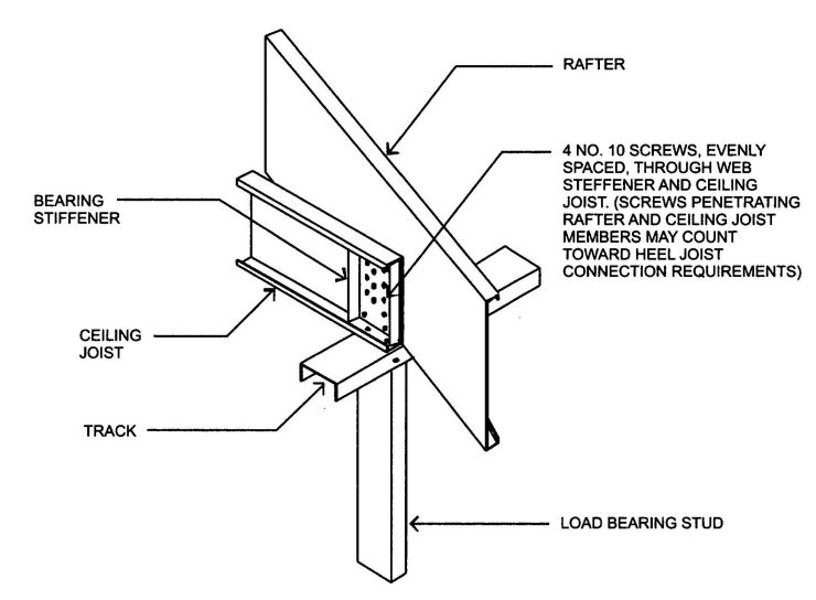
FIGURE R804.3.1.1(2)
BEARING STIFFENER
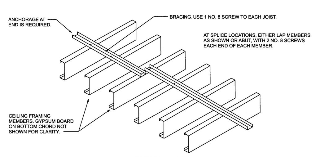
FIGURE R804.3.1.4(1)
CEILING JOIST TOP FLANGE BRACING WITH C-SHAPE, TRACK OR COLD-ROLLED CHANNEL
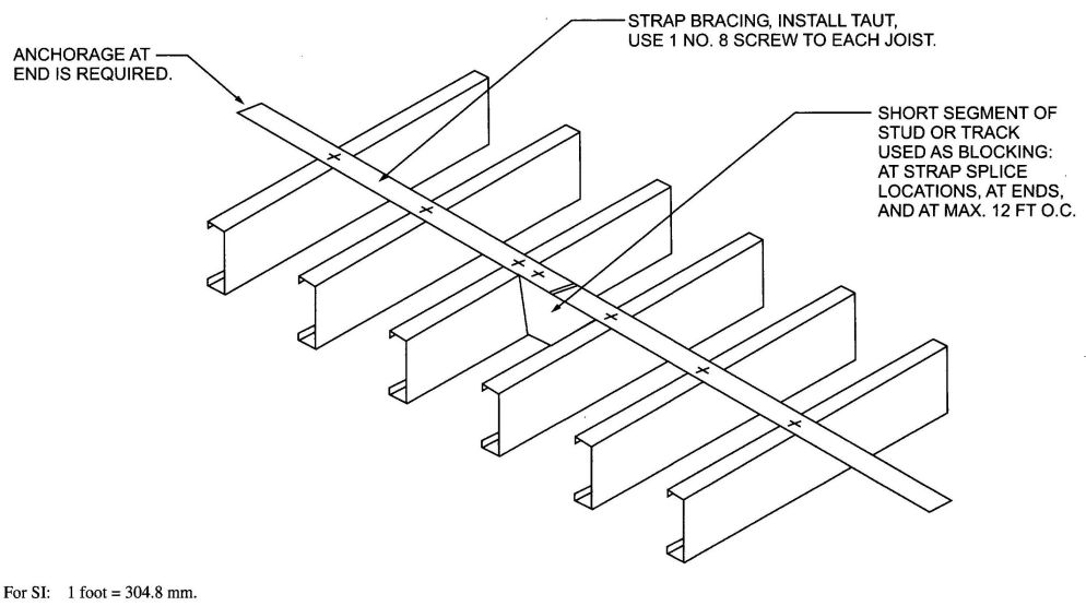
FIGURE R804.3.1.4(2)
CEILING JOIST TOP FLANGE BRACING WITH CONTINUOUS STEEL STRAP AND BLOCKING
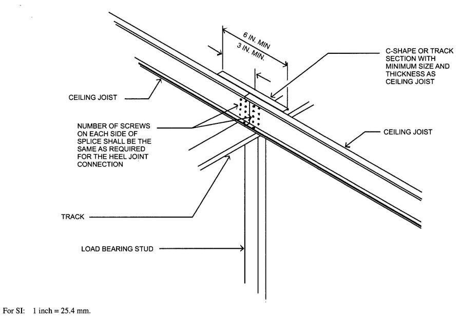
FIGURE R804.3.1.5
SPLICED CEILING JOISTS
| MEMBER DESIGNATION | ALLOWABLE SPAN MEASURED HORIZONTALLY (feet-inches) | |||||||
|---|---|---|---|---|---|---|---|---|
| Ground snow load (psf) | ||||||||
| 20 | 30 | 50 | 70 | |||||
| Rafter spacing (inches) | ||||||||
| 16 | 24 | 16 | 24 | 16 | 24 | 16 | 24 | |
| For SI: 1 inch = 25.4 mm, 1 foot = 304.8 mm, 1 pound per square foot = 0.0479kPa. | ||||||||
| a. Table provides maximum horizontal rafter spans in feet and inches for slopes between 3:12 and 12:12. | ||||||||
| b. Deflection criterion: L/240 for live loads andL/180 for total loads. | ||||||||
| c. Roof dead load = 12 psf. | ||||||||
| 550S162-33 | 14′;-0″ | 11′;-6″ | 11′;-11″ | 9′;-7″ | 9′;-6″ | 7′;-9″ | 8′;-2″ | 6′;-8″ |
| 550S162-43 | 16′;-8″ | 13′;-11″ | 14′;-5″ | 11′;-9″ | 11′;-6″ | 9′;-5″ | 9′;-10″ | 8′;-10″ |
| 550S162-54 | 17′;-11″ | 15′;-7″ | 15′;-7″ | 13′;-3″ | 12′;-11″ | 10′;-7″ | 11′;-1″ | 9′;-1″ |
| 550S162-68 | 19′;-2″ | 16′;-9″ | 16′;-9″ | 14′;-7″ | 14′;-1″ | 11′;-10″ | 12′;-6″ | 10′;-2″ |
| 550S162-97 | 21′;-3″ | 18′;-6″ | 18′;-6″ | 16′;-2″ | 15′;-8″ | 13′;-8″ | 14′;-0″ | 12′;-2″ |
| 800S162-33 | 16′;-5″ | 13′;-5″ | 13′;-11″ | 11′;-4″ | 11′;-1″ | 8′;-2″ | 9′;-0″ | 6′;-0″ |
| 800S162-43 | 19′;-9″ | 16′;-1″ | 16′;-8″ | 13′;-7″ | 13′;-4″ | 10′;-10″ | 11′;-5″ | 9′;-4″ |
| 800S162-54 | 22′;-8″ | 18′;-6″ | 19′;-2″ | 15′;-8″ | 15′;-4″ | 12′;-6″ | 13′;-1″ | 10′;-8″ |
| 800S162-68 | 25′;-10″ | 21′;-2″ | 21′;-11″ | 17′;-10″ | 17′;-6″ | 14′;-4″ | 15′;-0″ | 12′;-3″ |
| 800S162-97 | 21′;-3″ | 18′;-6″ | 18′;-6″ | 16′;-2″ | 15′;-8″ | 13′;-8″ | 14′;-0″ | 12′;-2″ |
| 1000S162-43 | 22′;-3″ | 18′;-2″ | 18′;-9″ | 15′;-8″ | 15′;-0″ | 12′;-3″ | 12′;-10″ | 10′;-6″ |
| 1000S162-54 | 25′;-8″ | 20′;-11″ | 21′;-8″ | 17′;-9″ | 17′;-4″ | 14′;-2″ | 14′;-10″ | 12′;-1″ |
| 1000S162-68 | 29′;-7″ | 24′;-2″ | 25′;-0″ | 20′;-5″ | 20′;-0″ | 16′;-4″ | 17′;-2″ | 14′;-0″ |
| 1000S162-97 | 34′;-8″ | 30′;-4″ | 30′;-4″ | 25′;-10″ | 25′;-3″ | 20′;-8″ | 21′;-8″ | 17′;-8″ |
| 1200S162-54 | 28′;-3″ | 23′;-1″ | 23′;-11″ | 19′;-7′; | 19′;-2″ | 15′;-7″ | 16′;-5″ | 13′;-5″ |
| 1200S162-68 | 32′;-10″ | 26′;-10″ | 27′;-9″ | 22′;-8″ | 22′;-2″ | 18′;-1″ | 19′;-0″ | 15′;-6″ |
| 1200S162-97 | 40′;-6″ | 33′;-5″ | 34′;-6″ | 28′;-3″ | 27′;-7″ | 22′;-7″ | 23′;-8″ | 19′;-4″ |
| MEMBER DESIGNATION | ALLOWABLE SPAN MEASURED HORIZONTALLY (feet-inches) | |||||||
|---|---|---|---|---|---|---|---|---|
| Ground snow load (psf) | ||||||||
| 20 | 30 | 50 | 70 | |||||
| Rafter spacing (inches) | ||||||||
| 16 | 24 | 16 | 24 | 16 | 24 | 16 | 24 | |
| For SI: 1 inch = 25.4 mm, 1 foot = 304.8 mm, 1 pound per square foot = 0.0479kPa. | ||||||||
| a. Table provides maximum horizontal rafter spans in feet and inches for slopes between 3:12 and 12:12. | ||||||||
| b. Deflection criterion: L/240 for live loads and L/180 for total loads. | ||||||||
| c. Roof dead load = 12 psf. | ||||||||
| 550S162-33 | 15′;-4″ | 12′;-11″ | 13′;-4″ | 10″-11″ | 10′;-9″ | 8′;-9″ | 9′;-2″ | 7′;-6″ |
| 550S162-43 | 16′;-8″ | 14′;-7″ | 14′;-7″ | 12′;-9″ | 12′;-3″ | 10′;-6″ | 11′;-0″ | 9′;-0″ |
| 550S162-54 | 17′;-11″ | 15′;-7″ | 15′;-7″ | 13′;-8″ | 13′;-2″ | 11′;-6″ | 11′;-9″ | 10′;-3″ |
| 550S162-68 | 19′;-2″ | 16′;-9″ | 16′;-9″ | 14′;-7″ | 14′;-1″ | 12′;-4″ | 12′;-7″ | 11′;-0″ |
| 550S162-97 | 21′;-3″ | 18′;-6″ | 18′;-6″ | 16′;-2″ | 15′;-8″ | 13′;-8″ | 14′;-0″ | 12′;-3″ |
| 800S162-33 | 18′;-10″ | 15′;-5″ | 15′;-11″ | 12′;-9″ | 12′;-3″ | 8′;-2″ | 9′;-0″ | 6′;-0″ |
| 800S162-43 | 22′;-3″ | 18′;-2″ | 18′;-10″ | 15′;-5″ | 15′;-1″ | 12′;-3″ | 12′;-11″ | 10′;-6″ |
| 800S162-54 | 24′;-2″ | 21′;-2″ | 21′;-1″ | 18′;-5″ | 17′;-10″ | 14′;-8″ | 15′;-5″ | 12′;-7″ |
| 800S162-68 | 25′;-11″ | 22′;-8″ | 22′;-8″ | 19′;-9″ | 19′;-1″ | 16′;-8″ | 17′;-1″ | 14′;-9″ |
| 800S162-97 | 28′;-10″ | 25′;-2″ | 25′;-2″ | 22′;-0″ | 21′;-2″ | 18′;-6″ | 19′;-0″ | 16′;-7″ |
| 1000S162-43 | 25′;-2″ | 20′;-7″ | 21′;-4″ | 17′;-5″ | 17′;-0″ | 13′;-11″ | 14′;-7″ | 10′;-7″ |
| 1000S162-54 | 29′;-0″ | 24′;-6″ | 25′;-4″ | 20′;-9″ | 20′;-3″ | 16′;-7″ | 17′;-5″ | 14′;-2″ |
| 1000S162-68 | 31′;-2″ | 27′;-3″ | 27′;-3″ | 23′;-9″ | 20′;-0″ | 19′;-6″ | 20′;-6″ | 16′;-8″ |
| 1000S162-97 | 34′;-8″ | 30′;-4″ | 30′;-4″ | 26′;-5″ | 25′;-7″ | 22′;-4″ | 22′;-10″ | 20′;-0″ |
| 1200S162-54 | 33′;-2″ | 27′;-1″ | 28′;-1″ | 22′;-11″ | 22′;-5″ | 18′;-4″ | 19′;-3″ | 15′;-8″ |
| 1200S162-68 | 36′;-4″ | 31′;-9″ | 31′;-9″ | 27′;-0″ | 26′;-5″ | 21′;-6″ | 22′;-6″ | 18′;-6″ |
| 1200S162-97 | 40′;-6″ | 35′;-4″ | 35′;-4″ | 30′;-11″ | 29′;-10″ | 26′;-1″ | 26′;-8″ | 23′;-1″ |
| BASIC WIND SPEED AND EXPOSURE | EQUIVALENT GROUND SNOW LOAD (psf) | ||||||||||
|---|---|---|---|---|---|---|---|---|---|---|---|
| Roof slope | |||||||||||
| Exp. B | Exp. C | 3:12 | 4:12 | 5:12 | 6:12 | 7:12 | 8:12 | 9:12 | 10:12 | 11:12 | 12:12 |
| For SI: 1 mile per hour = 0.447 m/s, 1 pound per square foot = 0.0479kPa. | |||||||||||
| 85 mph | — | 20 | 20 | 20 | 20 | 20 | 20 | 30 | 30 | 30 | 30 |
| 100 mph | 85 mph | 20 | 20 | 20 | 20 | 30 | 30 | 30 | 30 | 50 | 50 |
| 110 mph | 100 mph | 20 | 20 | 20 | 20 | 30 | 50 | 50 | 50 | 50 | 50 |
| — | 110 mph | 30 | 30 | 30 | 50 | 50 | 50 | 70 | 70 | 70 | — |
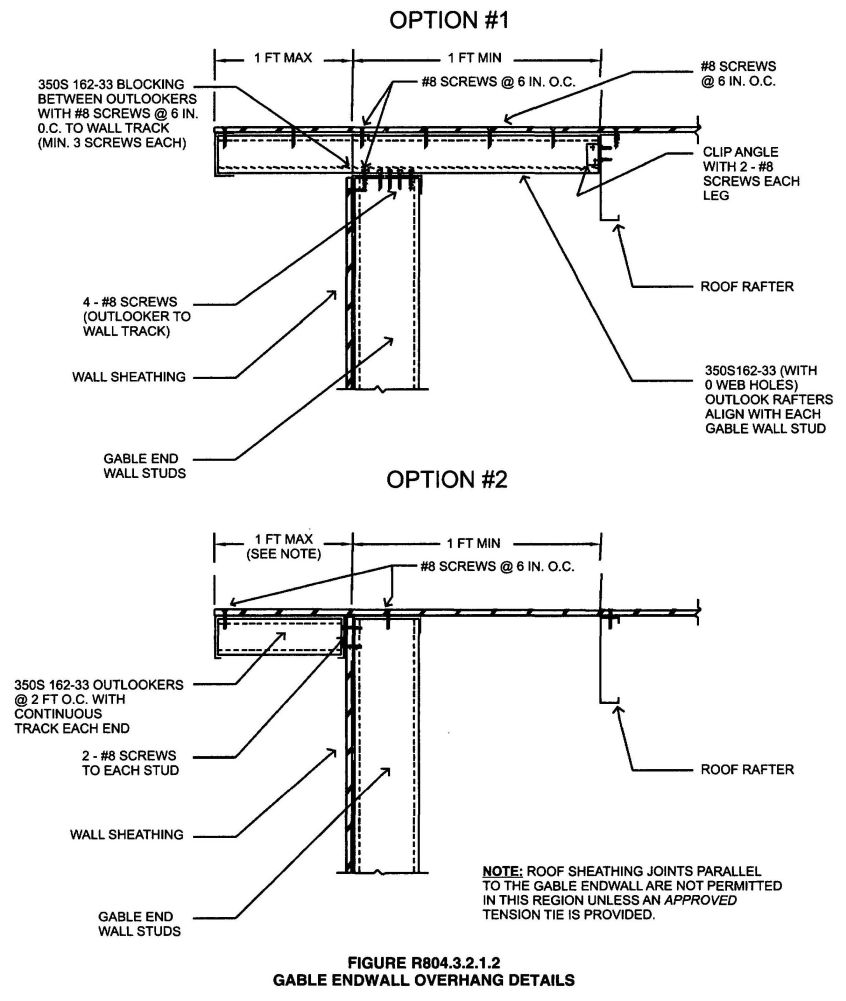
FIGURE R804.3.2.1.2
GABLE ENDWALL OVERHANG DETAILS
R804.3.4 Cutting and notching. Flanges and lips of load-bearing cold-formed steel roof framing members shall not be cut or notched.
R804.3.5 Headers. Roof-ceiling framing above wall openings shall be supported on headers. The allowable spans for headers in load-bearing walls shall not exceed the values set forth in Section R603.6 and Tables R603.6(1) through R603.6(24).
R804.3.6 Framing of openings in roofs and ceilings. Openings in roofs and ceilings shall be framed with header and trimmer joists. Header joist spans shall not exceed 4 feet (1219 mm) in length. Header and trimmer joists shall be fabricated from joist and track members having a minimum size and thickness at least equivalent to the adjacent ceiling joists or roof rafters and shall be installed in accordance with Figures R804.3.6(1) and R804.3.6(2). Each header joist shall be connected to trimmer joists with a minimum of four 2-inch by 2-inch (51 by 51 mm) clip angles. Each clip angle shall be fastened to both the header and trimmer joists with four No. 8 screws, evenly spaced, through each leg of the clip angle. The steel thickness of the clip angles shall be not less than that of the ceiling joist or roof rafter. Each track section for a built-up header or trimmer joist shall extend the full length of the joist (continuous).
R804.3.7 Roof trusses. Cold-formed steel trusses shall be designed and installed in accordance with AISI S100, Section D4. Trusses shall be connected to the top track of the load-bearing wall in accordance with Table R804.3, either with two No.10 screws applied through the flange of the truss or by using a 54 mil (1.37 mm) clip angle with two No. 10 screws in each leg.
R804.3.8 Ceiling and roof diaphragms. Ceiling and roof diaphragms shall be in accordance with this section.
R804.3.8.1 At gable endwalls a ceiling diaphragm shall be provided by attaching a minimum ½-inch (12.7 mm) gypsum board in accordance with Tables R804.3.8(1) and R804.3.8(2) or a minimum 3/8-inch (9.5 mm) wood structural panel sheathing, which complies with Section R803, in accordance with Table R804.6(3) to the bottom of ceiling joists or roof trusses and connected to wall framing in accordance with Figures R804.3.8(1) and R804.3.8(2), unless studs are designed as full height without bracing at the ceiling. Flat blocking shall consist of C-shape or track section with a minimum thickness of 33 mils (0.84 mm).
The ceiling diaphragm shall be secured with screws spaced at a maximum 6 inches (152 mm) o.c. at panel edges and a maximum 12 inches (305 mm) o.c. in the
| BUILDING WIDTH (feet) | NUMBER OF SCREWS | |||
|---|---|---|---|---|
| Ground snow load (psf) | ||||
| 0 to 20 | 21 to 30 | 31 to 50 | 51 to 70 | |
| For SI: 1 inch = 25.4 mm, 1 foot = 304.8 mm, 1 pound per square foot = 0.0479kPa. | ||||
| a. Screws shall be No. 10 minimum. | ||||
| 24 | 2 | 2 | 3 | 4 |
| 28 | 2 | 3 | 4 | 5 |
| 32 | 2 | 3 | 4 | 5 |
| 36 | 3 | 3 | 5 | 6 |
| 40 | 3 | 4 | 5 | 7 |
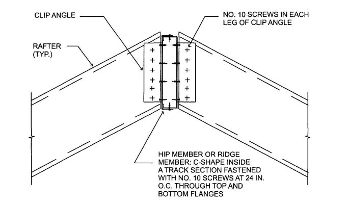
FIGURE R804.3.2.4
HIP MEMBER OR RIDGE MEMBER CONNECTION
field. Multiplying the required lengths in Tables R804.3.8(1) and R804.3.8(2) for gypsum board sheathed ceiling diaphragms shall be permitted to be multiplied by 0.35 shall be permitted if all panel edges are blocked. Multiplying the required lengths in Tables R804.3.8(1) and R804.3.8(2) for gypsum board sheathed ceiling diaphragms by 0.9 shall be permitted if all panel edges are secured with screws spaced at 4 inches (102 mm) o.c.
R804.3.8.2 Roof diaphragm. A roof diaphragm shall be provided by attaching a minimum of 3/8 inch (9.5 mm) wood structural panel which complies with Section R803 to roof rafters or truss top chords in accordance with Table R804.3. Buildings with 3:1 or larger plan aspect ratio and with roof rafter slope (pitch) of 9:12 or larger shall have the roof rafters and ceiling joists blocked in accordance with Figure R804.3.8(3).
R804.3.9 Roof tie-down. Roof assemblies subject to wind uplift pressures of 20 pounds per square foot (0.96 kPa) or greater, as established in Table R301.2(2), shall have rafter-to-bearing wall ties provided in accordance with Table R802.11.
R805.1 Ceiling installation. Ceilings shall be installed in accordance with the requirements for interior wall finishes as provided in Section R702.
R806.1 Ventilation required. Enclosed attics and enclosed rafter spaces formed where ceilings are applied directly to the underside of roof rafters shall have cross ventilation for each separate space by ventilating openings protected against the entrance of rain or snow. Ventilation openings shall have a least dimension of 1/16 inch (1.6 mm) minimum and ¼ inch (6.4 mm) maximum. Ventilation openings having a least dimension larger than ¼ inch (6.4 mm) shall be provided with corrosion-resistant wire cloth screening, hardware cloth, or similar material with openings having a least dimension of 1/16 inch (1.6 mm) minimum and ¼ inch (6.4 mm) maximum. Openings in roof framing members shall conform to the requirements of Section R802.7.
| BUILDING WIDTH (feet) | HIP MEMBER DESIGNATIONa | |||
|---|---|---|---|---|
| Equivalent ground snow load (psf) | ||||
| 0 to 20 | 21 to 30 | 31 to 50 | 51 to 70 | |
| For SI: 1 foot = 304.8 mm, 1 pound per square foot = 0.0479 kPa. | ||||
| a. The web depth of the roof rafters and jack rafters is to match at the hip or they shall be installed in accordance with an approved design. | ||||
| 24 | 800S162-68 800T150-68 | 800S162-68 800T150-68 | 800S162-97 800T150-97 | 1000S162-97 1000T150-97 |
| 28 | 1000S162-68 1000T150-68 | 1000S162-68 1000T150-68 | 1000S162-97 1000T150-97 | 1200S162-97 1200T150-97 |
| 32 | 1000S162-97 1000T150-97 | 1000S162-97 1000T150-97 | 1200S162-97 1200T150-97 | — |
| 36 | 1200S162-97 1200T150-97 | — | — | — |
| 40 | — | — | — | — |
| BUILDING WIDTH (feet) | HIP SUPPORT COLUMN DESIGNATIONa, b | |||
|---|---|---|---|---|
| Equivalent ground snow load (psf) | ||||
| 0 to 20 | 21 to 30 | 31 to 50 | 51 to 70 | |
| For SI: 1 foot = 304.8 mm, 1 pound per square foot = 0.0479kPa. | ||||
| a. Box shape column only in accordance with Figure R804.3.3.4(2). | ||||
| b. 33 ksi steel for 33 and 43 mil material; 50 ksi steel for thicker material. | ||||
| 24 | 2-350S162-33 | 2-350S162-33 | 2-350S162-43 | 2-350S162-54 |
| 28 | 2-350S162-54 | 2-550S162-54 | 2-550S162-68 | 2-550S162-68 |
| 32 | 2-550S162-68 | 2-550S162-68 | 2-550S162-97 | — |
| 36 | 2-550S162-97 | — | — | — |
| 40 | — | — | — | — |
| BUILDING WIDTH (feet) | BASIC WIND SPEED (mph) EXPOSURE B | ||||
|---|---|---|---|---|---|
| 85 | 100 | 110 | — | — | |
| BASIC WIND SPEED (mph) EXPOSURE C | |||||
| — | 85 | — | 100 | 110 | |
| Number of No. 10 screws in each end of each 3 inch by 54-mil steel strapa, b, c | |||||
| For SI: 1 foot = 304.8 mm, 1 pound per square foot = 0.0479kPa, 1 mil = 0.0254 mm. | |||||
| a. Two straps are required, one each side of the column. | |||||
| b. Space screws at ¾ inch on-center and provide ¾ inch end distance. | |||||
| c. 50 ksi steel strap. | |||||
| 24 | 3 | 4 | 4 | 6 | 7 |
| 28 | 4 | 6 | 6 | 8 | 10 |
| 32 | 5 | 8 | 8 | 11 | 13 |
| 36 | 7 | 10 | 11 | 14 | 17 |
| 40 | — | — | — | — | — |
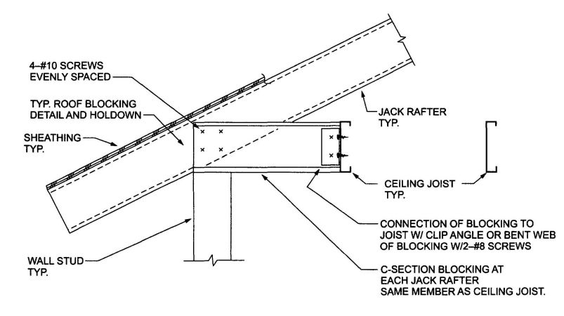
FIGURE R804.3.3.4(1)
JACK RAFTER CONNECTION AT EAVE
| BUILDING WIDTH (feet) | NUMBER OF NO. 10 SCREWS IN EACH FRAMING ANGLEa, b, c | |||
|---|---|---|---|---|
| Equivalent ground snow load (psf) | ||||
| 0 to 20 | 21 to 30 | 31 to 50 | 51 to 70 | |
| For SI: 1 foot = 304.8 mm, 1 pound per square foot = 0.0479 kPa. | ||||
| a. Screws to be divided equally between the connection to the hip member and the column. Refer to Figures R804.3.3.4(3) and R804.3.3.4(4). | ||||
| b. The number of screws required in each framing angle is not to be less than shown in Table R804.3.3.4(1). | ||||
| c. 50 ksi steel from the framing angle. | ||||
| 24 | 10 | 10 | 10 | 12 |
| 28 | 10 | 10 | 14 | 18 |
| 32 | 10 | 12 | — | — |
| 36 | 14 | — | — | — |
| 40 | — | — | — | — |
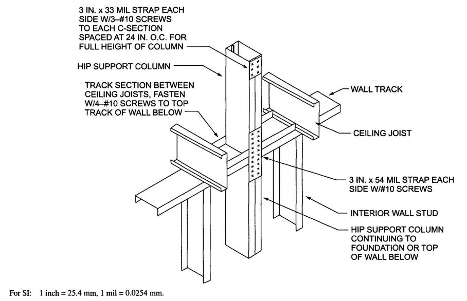
FIGURE R804.3.3.4(2)
HIP SUPPORT COLUMN
| BUILDING WIDTH (feet) | BASIC WIND SPEED (mph) EXPOSURE B | ||||
|---|---|---|---|---|---|
| 85 | 100 | 110 | — | — | |
| BASIC WIND SPEED (mph) EXPOSURE C | |||||
| — | 85 | — | 100 | 110 | |
| Number of No. 10 screws in each end of each 3 inch by 54-mil Steel strapa, b, c | |||||
| For SI: 1 foot = 304.8 mm, 1 pound per square foot = 0.0479 kPa. | |||||
| a. Two straps are required, one each side of the column. | |||||
| b. Space screws at ¾ inches on-center and provide ¾ inch end distance. | |||||
| c. 50 ksi steel strap. | |||||
| 24 | 2 | 2 | 3 | 3 | 4 |
| 28 | 2 | 3 | 3 | 4 | 5 |
| 32 | 3 | 4 | 4 | 6 | 7 |
| 36 | 3 | 5 | 5 | 7 | 8 |
| 40 | — | — | — | — | — |
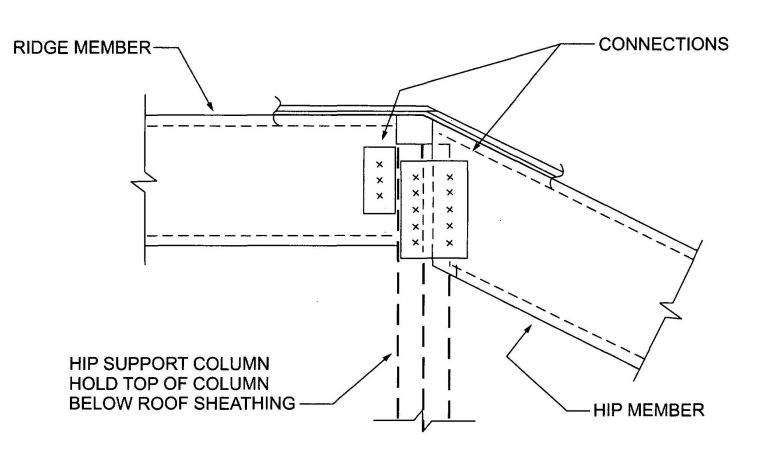
FIGURE R804.3.3.4(3)
HIP CONNECTIONS AT RIDGE
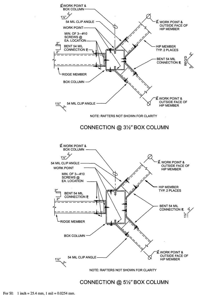
FIGURE R804.3.3.4(4)
HIP CONNECTIONS AT RIDGE AND BOX COLUMN
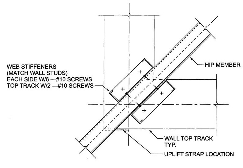
FIGURE R804.3.3.4(5)
HIP MEMBER CONNECTION AT WALL CORNER
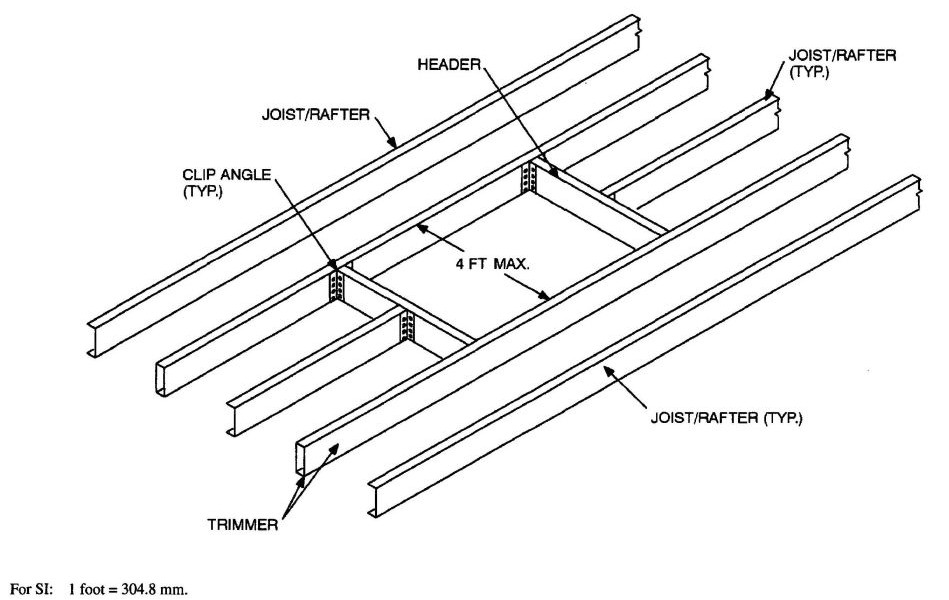
FIGURE R804.3.6(1)
ROOF OR CEILING OPENING
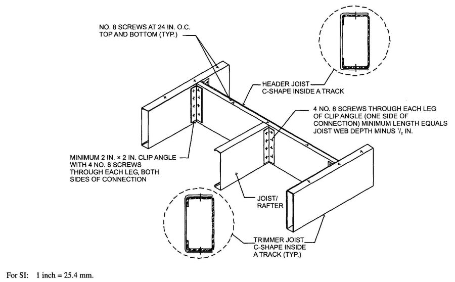
FIGURE R804.3.6(2)
HEADER TO TRIMMER CONNECTION
| Exposure B | BASIC WIND SPEED (mph) | |||||
|---|---|---|---|---|---|---|
| 85 | 100 | 110 | — | — | ||
| Exposure C | — | 85 | — | 100 | 110 | |
| Roof pitch | Building endwall width (feet) | Minimum diaphragm length (feet) | ||||
| For SI: 1 inch = 25.4 mm, 1 pound per square foot = 0.0479 kPa, 1 mile per hour = 0.447 m/s, 1 foot = 304.8 mm, 1 mil = 0.0254 mm. | ||||||
| a. Ceiling diaphragm is composed of ½ inch gypsum board (min. thickness) secured with screws spaced at 6 inches o.c. at panel edges and 12 inches o.c. in field. Use No. 8 screws (min.) when framing members have a designation thickness of 54 mils or less and No. 10 screws (min). when framing members have a designation thickness greater than 54 mils. | ||||||
| b. Maximum aspect ratio (length/width) of diaphragms is 2:1. | ||||||
| c. Building width is in the direction of horizontal framing members supported by the wall studs. | ||||||
| d. Required diaphragm lengths are to be provided at each end of the structure. | ||||||
| e. Multiplying required diaphragm lengths by 0.35 is permitted if all panel edges are blocked. | ||||||
| f. Multiplying required diaphragm lengths by 0.9 is permitted if all panel edges are secured with screws spaced at 4 inches o.c. | ||||||
| 3:12 to 6:12 | 24 - 28 | 14 | 20 | 22 | 28 | 32 |
| 28 - 32 | 16 | 22 | 28 | 32 | 38 | |
| 32 - 36 | 20 | 26 | 32 | 38 | 44 | |
| 36 - 40 | 22 | 30 | 36 | 44 | 50 | |
| 6:12 to 9:12 | 24 - 28 | 16 | 22 | 26 | 32 | 36 |
| 28 - 32 | 20 | 26 | 32 | 38 | 44 | |
| 32 - 36 | 22 | 32 | 38 | 44 | 52 | |
| 36 - 40 | 26 | 36 | 44 | 52 | 60 | |
| 9:12 to 12:12 | 24 - 28 | 18 | 26 | 30 | 36 | 42 |
| 28 - 32 | 22 | 30 | 36 | 42 | 50 | |
| 32 - 36 | 26 | 36 | 42 | 50 | 60 | |
| 36 - 40 | 30 | 42 | 50 | 60 | 70 | |
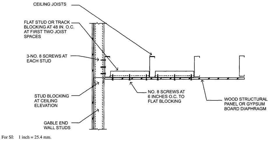
FIGURE R804.3.8(1)
CEILING DIAPHRGAM TO GABLE ENDWALL, DETAIL
| Exposure B | BASIC WIND SPEED (mph) | |||||
|---|---|---|---|---|---|---|
| 85 | 100 | 110 | — | — | ||
| Exposure C | — | 85 | — | 100 | 110 | |
| Roof pitch | Building endwall width (feet) | Minimum diaphragm length (feet) | ||||
| For SI: 1 inch = 25.4 mm, 1 pound per square foot = 0.0479kPa, 1 mph = 0.447 m/s, 1 foot = 304.8 mm, 1 mil = 0.0254 mm. | ||||||
| a. Ceiling diaphragm is composed of ½ inch gypsum board (min. thickness) secured with screws spaced at 6 inches o.c. at panel edges and 12 inches o.c. in field. Use No. 8 screws (min.) when framing members have a designation thickness of 54 mils or less and No. 10 screws (min.) when framing members have a designation thickness greater than 54 mils. | ||||||
| b. Maximum aspect ratio (length/width) of diaphragms is 2:1. | ||||||
| c. Building width is in the direction of horizontal framing members supported by the wall studs. | ||||||
| d. Required diaphragm lengths are to be provided at each end of the structure. | ||||||
| e. Required diaphragm lengths are permitted to be multiplied by 0.35 if all panel edges are blocked. | ||||||
| f. Required diaphragm lengths are permitted to be multiplied by 0.9 if all panel edges are secured with screws spaced at 4 inches o.c. | ||||||
| 3:12 to 6:12 | 24-28 | 16 | 22 | 26 | 32 | 38 |
| 28-32 | 20 | 26 | 32 | 38 | 44 | |
| 32-36 | 22 | 30 | 36 | 44 | 50 | |
| 36-40 | 26 | 36 | 42 | 50 | 58 | |
| 6:12 to 9:12 | 24-28 | 18 | 26 | 30 | 36 | 42 |
| 28-32 | 22 | 30 | 36 | 42 | 50 | |
| 32-36 | 26 | 36 | 42 | 50 | 58 | |
| 36-40 | 30 | 42 | 48 | 58 | 68 | |
| 9:12 to 12:12 | 24-28 | 20 | 28 | 34 | 40 | 46 |
| 24-32 | 24 | 34 | 40 | 48 | 56 | |
| 32-36 | 28 | 40 | 48 | 56 | 66 | |
| 36-40 | 34 | 46 | 56 | 66 | 78 | |
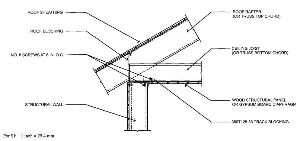
FIGURE R804.3.8(2)
CEILING DIAPHRAGM TO SIDEWALL DETAIL
| Exposure B | BASIC WIND SPEED (mph) | |||||
|---|---|---|---|---|---|---|
| 85 | 100 | 110 | — | — | ||
| Exposure C | — | 85 | — | 100 | 110 | |
| Roof pitch | Building endwall width (feet) | Minimum diaphragm length (feet) | ||||
| For SI: 1 inch = 25.4 mm, 1 pound per square foot = 0.0479kPa, 1 mile per hour = 0.447 m/s, 1 foot = 304.8 mm, 1 mil = 0.0254 mm. | ||||||
| a. Ceiling diaphragm is composed of⁄38; inch wood structural panel sheathing (min. thickness) secured with screws spaced at 6 inches o.c. at panel edges and in field. Use No. 8 screws (min.) when framing members have a designation thickness of 54 mils or less and No. 10 screws (min.) when framing members have a designation thickness greater than 54 mils. | ||||||
| b. Maximum aspect ratio (length/width) of diaphragms is 3:1. | ||||||
| c. Building width is in the direction of horizontal framing members supported by the wall studs. | ||||||
| d. Required diaphragm lengths are to be provided at each end of the structure. | ||||||
| 3:12 to 6:12 | 24-28 | 10 | 10 | 10 | 10 | 10 |
| 28-32 | 12 | 12 | 12 | 12 | 12 | |
| 32-36 | 12 | 12 | 12 | 12 | 12 | |
| 36-40 | 14 | 14 | 14 | 14 | 14 | |
| 6:12 to 9:12 | 24-28 | 10 | 10 | 10 | 10 | 10 |
| 28-32 | 12 | 12 | 12 | 12 | 12 | |
| 32-36 | 12 | 12 | 12 | 12 | 12 | |
| 36-40 | 14 | 14 | 14 | 14 | 14 | |
| 9:12 to 12:12 | 24-28 | 10 | 10 | 10 | 10 | 10 |
| 28-32 | 12 | 12 | 12 | 12 | 12 | |
| 32-36 | 12 | 12 | 12 | 12 | 12 | |
| 36-40 | 14 | 14 | 14 | 14 | 14 | |
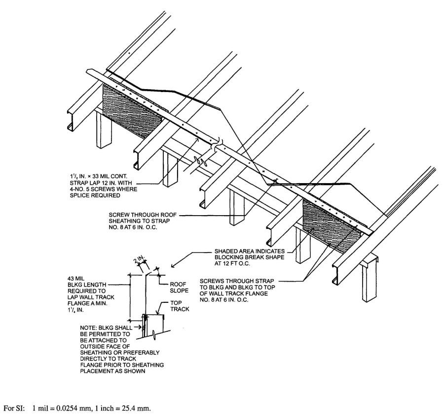
FIGURE R804.3.8(3)
ROOF BLOCKING DETAIL
R806.2 Minimum area. The total net free ventilating area shall not be less than⁄1150 of the area of the space ventilated except that reduction of the total area to⁄1300; is permitted provided that at least 50 percent and not more than 80 percent of the required ventilating area is provided by ventilators located in the upper portion of the space to be ventilated at least 3 feet (914 mm) above the eave or cornice vents with the balance of the required ventilation provided by eave or cornice vents. As an alternative, the net free cross-ventilation area may be reduced to⁄1300; when a Class I or II vapor barrier is installed on the warm-in-winter side of the ceiling.
R806.3 Vent and insulation clearance. Where evae or cornice vents are installed, insulation shall not block the free flow of air. A minimum of a 1-inch (25 mm) space shall be provided between the insulation and the roof sheathing and at the location of the vent.
R806.4 Unvented attic assemblies. Unvented attic assemblies (spaces between the ceiling joists of the top story and the roof rafters) shall be permitted if all the following conditions are met:
R807.1 Attic access. Buildings with combustible ceiling or roof construction shall have an attic access opening to attic areas that exceed 30 square feet (2.8 m2) and have a vertical height of 30 inches (762 mm) or greater. The vertical height shall be measured from the top of the ceiling framing members to the underside of the roof framing members.
The rough-framed opening shall not be less than 22 inches by 30 inches (559 mm by 762 mm) and shall be located in a hallway or other readily accessible location. When located in a wall, the opening shall be minimum of 22 inches wide by 30 inches high. When the access is located in a ceiling, minimum unobstructed headroom in the attic space shall be 30 inches (762 mm) at some point above the access measured vertically from the bottom of ceiling framing members. See the California Mechanical Code for access requirements where mechanical equipment is located in attics.
| Adopting agency | BSC | SFM | HCD | DSA | OSHPD | CSA | DPH | AGR | DWR | CEC | CA | SL | SLC | ||||||
|---|---|---|---|---|---|---|---|---|---|---|---|---|---|---|---|---|---|---|---|
| 1 | 2 | 1-AC | AC | SS | 1 | 2 | 3 | 4 | |||||||||||
| Adopt entire chapter | |||||||||||||||||||
| Adopt entire chapter as amended (amended sections listed below) |
X | X | |||||||||||||||||
| Adopt only those sections that are listed below |
X | ||||||||||||||||||
| Chapter/Section | |||||||||||||||||||
| R901.1 | X | ||||||||||||||||||
| R902.1 through R902.2 | X | ||||||||||||||||||
| R903.4.1 | X | X | |||||||||||||||||
| R904.1 through R904.4 | X | ||||||||||||||||||
| R905.10.3 | X | X | |||||||||||||||||
R901.1 Scope.The provisions of this Chapter shall govern the design, materials, construction and quality of roof assemblies.
R902.1 Roofing covering materials. Roofs shall be covered with materials as set forth in Sections R904 and R905. A minimum Class A, B and C roofing required by this section to be listed shall be tested in accordance with UL 790 or ASTM E 108.
Exceptions:
- Class A roof assemblies include those with coverings of brick, masonry and exposed concrete roof deck.
- Class A roof assemblies also include ferrous or copper shingles or sheets, metal sheets and shingles, clay or concrete roof tile, or slate installed on noncombustible decks.
R902.1.1 Roof coverings within Very-High Fire Hazard Severity Zones. The entire roof covering of every existing structure where more than 50 percent of the total roof area is replaced within any one-year period, the entire roof covering of every new structure, and any roof covering applied in the alteration, repair or replacement of the roof of every existing structure, shall be a fire-retardant roof covering that is at least Class A.
Exception: The requirements shall not apply in any jurisdiction that adopts the model ordinance approved by the State Fire Marshal pursuant to Section 51189 of the Government Code or an ordinance that substantially conforms to the model ordinance and transmits a copy to the State Fire Marshal.
R902.1.2 Roof coverings within State Responsibility Areas. The entire roof covering of every existing structure where more than 50 percent of the total roof area is replaced within any one-year period, the entire roof covering of every new structure, and any roof covering applied in the alteration, repair or replacement of the roof of every existing structure, shall be a fire-retardant roof covering that is at least Class B.
Exception: Areas designated as moderate fire hazard severity zones.
R902.1.3 Roof coverings in all other areas. The entire roof covering of every existing structure where more than 50 percent of the total roof area is replaced within any one-year period, the entire roof covering of every new structure, and any roof covering applied in the alteration, repair or replacement of the roof of every existing structure, shall be a fire-retardant roof covering that is at least Class C.
R902.1.4 Roofing requirements a Wildland-Urban Interface Fire Area. Roofing requirements for structures located in a Wildland-Urban Interface Fire Area shall also comply with Section R327.5.
R902.2 Fire-retardant-treated shingles and shakes.Fire retardant-treated wood shakes and shingles are wood shakes and shingles complying with UBC Standard 15-3 or 15-4 which are impregnated by the full-cell vacuum-pressure process with fire-retardant chemicals, and which have been qualified by UBC Standard 15-2 for use on Class A, B or C roofs.
Fire-retardant-treated wood shakes and shingles shall comply with ICC-ES EG107 and with the weathering requirements contained in Health and Safety Code Section 13132.7 (j). Each bundle shall bear labels from an ICBO accredited quality control agency identifying their roof-covering classification and indicating their compliance with ICC-ES EG107 and with the weathering requirements contained in Health and Safety Code Section 13132.7 (j).
Health and Safety Code Section 13132.7 (j) No wood roof covering materials shall be sold or applied in this state unless both of the following conditions are met:
R903.1 General. Roof decks shall be covered with approved roof coverings secured to the building or structure in accordance with the provisions of this chapter. Roof assemblies shall be designed and installed in accordance with this code and the approved manufacturer’s installation instructions such that the roof assembly shall serve to protect the building or structure.
R903.2 Flashing. Flashings shall be installed in a manner that prevents moisture from entering the wall and roof through joints in copings, through moisture permeable materials and at intersections with parapet walls and other penetrations through the roof plane.
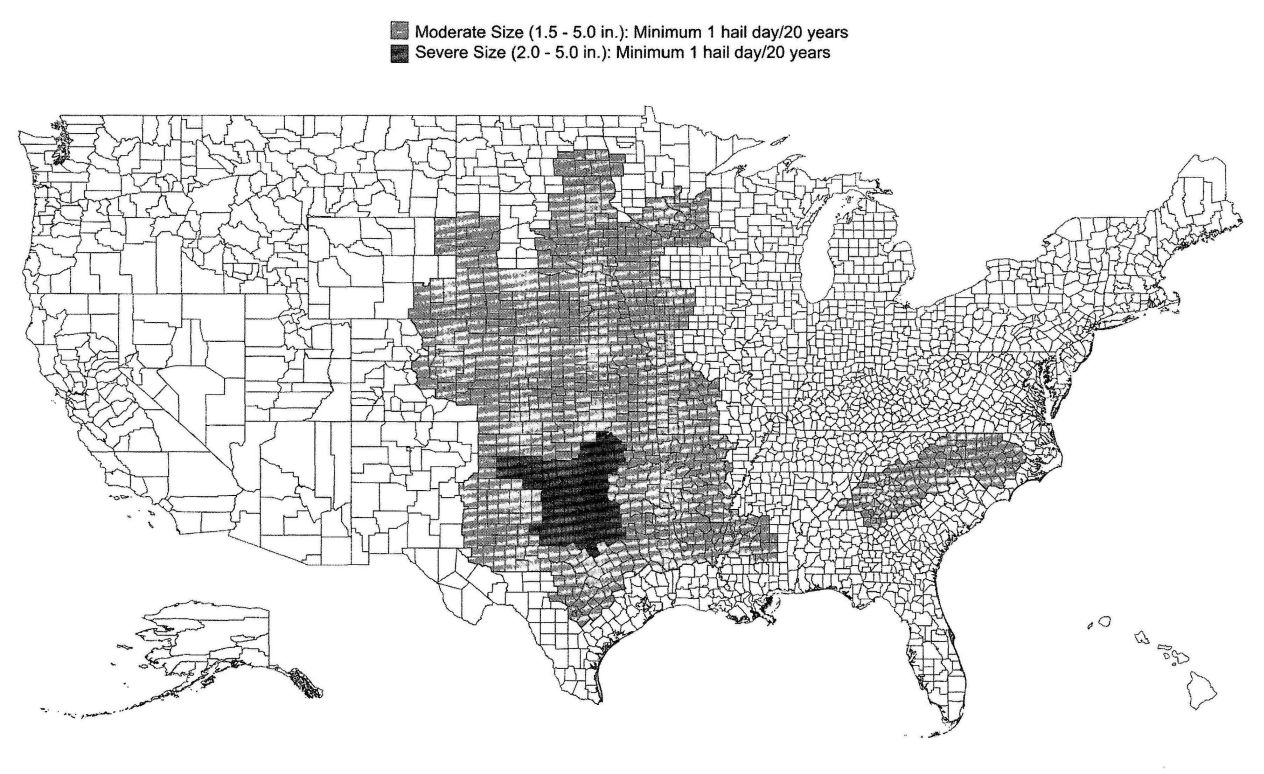
FIGURE R903.5
HAIL EXPOSURE MAP
R903.2.1 Locations. Flashings shall be installed at wall and roof intersections, wherever there is a change in roof slope or direction and around roof openings. Where flashing is of metal, the metal shall be corrosion resistant with a thickness of not less than 0.019 inch (0.5 mm) (No.26 galvanized sheet).
R903.2.2 Crickets and saddles. A cricket or saddle shall be installed on the ridge side of any chimney or penetration more than 30 inches (762 mm) wide as measured perpendicular to the slope. Cricket or saddle coverings shall be sheet metal or of the same material as the roof covering.
R903.3 Coping. Parapet walls shall be properly coped with noncombustible, weatherproof materials of a width no less than the thickness of the parapet wall.
R903.4 Roof drainage. Unless roofs are sloped to drain over roof edges, roof drains shall be installed at each low point of the roof. Where required for roof drainage, scuppers shall be placed level with the roof surface in a wall or parapet. The scupper shall be located as determined by the roof slope and contributing roof area.
R903.4.1 Overflow drains and scuppers. Where roof drains are required, overflow drains having the same size as the roof drains shall be installed with the inlet flow line located 2 inches (51 mm) above the low point of the roof, or overflow scuppers having three times the size of the roof drains and having a minimum opening height of 4 inches (102 mm) shall be installed in the adjacent parapet walls with the inlet flow located 2 inches (51 mm) above the low point of the roof served. The installation and sizing of overflow drains, leaders and conductors shall comply with the California Plumbing Code.
R903.5 Hail exposure. Hail exposure, as specified in Sections R903.5.1 and R903.5.2, shall be determined using Figure R903.5.
R903.5.1 Moderate hail exposure. One or more hail days with hail diameters larger than 1.5 inches (38 mm) in a 20-year period.
R903.5.2 Severe hail exposure. One or more hail days with hail diameters larger than or equal to 2.0 inches (51 mm) in a 20-year period.
R904.1 Scope. The requirements set forth in this section shall apply to the application of roof covering materials specified herein. Roof assemblies shall be applied in accordance with this chapter and the manufacturer’s installation instructions. Installation of roof assemblies shall comply with the applicable provisions of Section R905.
R904.2 Compatibility of materials. Roof assemblies shall be of materials that are compatible with each other and with the building or structure to which the materials are applied.
R904.3 Material specifications and physical characteristics. Roof covering materials shall conform to the applicable standards listed in this chapter. In the absence of applicable standards or where materials are of questionable suitability, testing by an approved testing agency shall be required by the building official to determine the character, quality and limitations of application of the materials.
R904.4 Product identification. Roof covering materials shall be delivered in packages bearing the manufacturer’s identifying marks and approved testing agency labels when required. Bulk shipments of materials shall be accompanied by the same information issued in the form of a certificate or on a bill of lading by the manufacturer.
R905.1 Roof covering application. Roof coverings shall be applied in accordance with the applicable provisions of this section and the manufacturer’s installation instructions. Unless otherwise specified in this section, roof coverings shall be installed to resist the component and cladding loads specified in Table R301.2(2), adjusted for height and exposure in accordance with Table R301.2(3).
R905.2 Asphalt shingles. The installation of asphalt shingles shall comply with the provisions of this section.
R905.2.1 Sheathing requirements.Asphalt shingles shall be fastened to solidly sheathed decks.
R905.2.2 Slope.Asphalt shingles shall be used only on roof slopes of two units vertical in 12 units horizontal (2:12) or greater. For roof slopes from two units vertical in 12 units horizontal (2:12) up to four units vertical in 12 units horizontal (4:12), double underlayment application is required in accordance with Section R905.2.7.
R905.2.3 Underlayment.Unless otherwise noted, required underlayment shall conform to ASTM D 226 Type 1, ASTM D4869 Type 1, or ASTM D 6757.
Self-adhering polymer modified bitumen sheet shall comply with ASTM D 1970.
R905.2.4 Asphalt shingles. Asphalt shingles shall comply with ASTM D 225 or D 3462.
R905.2.4.1 Wind resistance of asphalt shingles. Asphalt shingles shall be tested in accordance with ASTM D 7158. Asphalt shingles shall meet the classification requirements of Table R905.2.4.1(1) for the appropriate maximum basic wind speed. Asphalt shingles packaging shall bear a label to indicate compliance with ASTM D 7158 and the required classification in Table R905.2.4.1(1).
Exception:Asphalt shingles not included in the scope of ASTM D 7158 shall be tested and labeled to indicate compliance with ASTM D 3161 and the required classification in Table R905.2.4.1(2).
R905.2.5 Fasteners. Fasteners for asphalt shingles shall be galvanized steel, stainless steel, aluminum or copper roofing nails, minimum 12 gage [0.105 inch (3 mm)] shank with a minimum 3/8 inch (10 mm) diameter head, ASTM F 1667, of a length to penetrate through the roofing materials and a minimum of ¾ inch (19 mm) into the roof sheathing. Where the roof sheathing is less than ¾ inch (19 mm) thick, the fasteners shall penetrate through the sheathing. Fasteners shall comply with ASTM F 1667.
495| MAXIMUM BASIC WIND SPEED FROM FIGURE 301.2(4) (mph) | CLASSIFICATION REQUIREMENT |
|---|---|
| For SI: 1 mile per hour = 0.447 m/s. | |
| 85 | D, G or H |
| 90 | D, G or H |
| 100 | G or H |
| 110 | G or H |
| 120 | G or H |
| 130 | H |
| 140 | H |
| 150 | H |
| MAXIMUM BASIC WIND SPEED FROM FIGURE 301.2(4) (mph) | CLASSIFICATION REQUIREMENT |
|---|---|
| For SI: 1 mile per hour = 0.447 m/s. | |
| 85 | A, D or F |
| 90 | A, D or F |
| 100 | A, D or F |
| 110 | F |
| 120 | F |
| 130 | F |
| 140 | F |
| 150 | F |
R905.2.6 Attachment. A sphalt shingles shall have the minimum number of fasteners required by the manufacturer, but not less than four fasteners per strip shingle or two fasteners per individual shingle. Where the roof slope exceeds 21 units vertical in 12 units horizontal (21:12, 175 percent slope), shingles shall be installed as required by the manufacturer.
R905.2.7 Underlayment application. For roof slopes from two units vertical in 12 units horizontal (17-percent slope), up to four units vertical in 12 units horizontal (33-percent slope), underlayment shall be two layers applied in the following manner. Apply a 19-inch (483 mm) strip of underlayment felt parallel to and starting at the eaves, fastened sufficiently to hold in place. Starting at the eave, apply 36-inch-wide (914 mm) sheets of underlayment, overlapping successive sheets 19 inches (483 mm), and fastened sufficiently to hold in place. Distortions in the underlayment shall not interfere with the ability of the shingles to seal. For roof slopes of four units vertical in 12 units horizontal (33-percent slope) or greater, underlayment shall be one layer applied in the following manner. Underlayment shall be applied shingle fashion, parallel to and starting from the eave and lapped 2 inches (51 mm), fastened sufficiently to hold in place. Distortions in the underlayment shall not interfere with the ability of the shingles to seal. End laps shall be offset by 6 feet (1829 mm).
R905.2.7.1 Ice barrier. In areas where there has been a history of ice forming along the eaves causing a backup of water as designated in Table R301.2(1), an ice barrier that consists of a least two layers of underlayment cemented together or of a self-adhering polymer modified bitumen sheet, shall be used in lieu of normal underlayment and extend from the lowest edges of all roof surfaces to a point at least 24 inches (610 mm) inside the exterior wall line of the building.
Exception: Detached accessory structures that contain no conditioned floor area.
R905.2.7.2 Underlayment and high wind. Underlayment applied in areas subject to high winds [above 110 mph (49 m/s) per Figure R301.2(4)] shall be applied with corrosion-resistant fastners in accordance with manufacturer’s installation instructions. Fasteners are to be applied along the overlap not farther apart than 36 inches (914 mm) on center.
R905.2.8 Flashing. Flashing for asphalt shingles shall comply with this section.
R905.2.8.1 Base and cap flashing. Base and cap flashing shall be installed in accordance with manufacturer’s installation instructions. Base flashing shall be of either corrosion-resistant metal of minimum nominal 0.019-inch (0.5 mm) thickness or mineral surface roll roofing weighing a minimum of 77 pounds per 100 square feet (4 kg/m2). Cap
496flashing shall be corrosion-resistant metal of minimum nominal 0.019-inch (0.5 mm) thickness.
R905.2.8.2 Valleys. Valley linings shall be installed in accordance with the manufacturer’s installation instructions before applying shingles. Valley linings of the following types shall be permitted:
| MATERIAL | MINIMUM THICKNESS (inches) | GAGE | WEIGHT (pounds) |
|---|---|---|---|
| For SI: 1 inch = 25.4 mm, 1 pound = 0.454 kg. | |||
| Cold-rolled copper | 0.0216 nominal | — | ASTM B 370,16 oz. per square foot |
| Lead-coated copper | 0.0216 nominal | — | ASTM B 101, 16 oz. per square foot |
| High-yield copper | 0.0162 nominal | — | ASTM B 370, 12 oz. per square foot |
| Lead-coated high-yield copper | 0.0162 nominal | — | ASTM B 101, 12 oz. per square foot |
| Aluminum | 0.024 | — | — |
| Stainless steel | — | 28 | — |
| Galvanized steel | 0.0179 | 26 (zinc coated G90) | — |
| Zinc alloy | 0.027 | — | — |
| Lead | — | — | 2½ |
| Painted terne | — | — | 20 |
R905.2.8.3 Sidewall flashing. Flashing against a vertical sidewall shall be by the step-flashing method. The flashing shall be a minimum of 4 inches (102 mm) high and 4 inches (102 mm) wide. At the end of the vertical sidewall the step flashing shall be turned out in a manner that directs water away from the wall and onto the roof and/or gutter.
R905.2.8.4 Other flashing. Flashing against a vertical front wall, as well as soil stack, vent pipe and chimney flashing, shall be applied according to the asphalt shingle manufacturer’s printed instructions.
R905.3 Clay and concrete tile. The installation of clay and concrete tile shall comply with the provisions of this section.
R905.3.1 Deck requirements. Concrete and clay tile shall be installed only over solid sheathing or spaced structural sheathing boards.
R905.3.2 Deck slope. Clay and concrete roof tile shall be installed on roof slopes of two and one-half units vertical in 12 units horizontal (2½:12) or greater. For roof slopes from two and one-half units vertical in 12 units horizontal (2½12) to four units vertical in 12 units horizontal (4:12), double underlayment application is required in accordance with Section R905.3.3.
R905.3.3 Underlayment. Unless otherwise noted, required underlayment shall conform to ASTM D 226 Type II; ASTM D 2626 Type I; or ASTM D 6380 Class M mineral surfaced roll roofing.
R905.3.3.1 Low slope roofs. For roof slopes from two and one-half units vertical in 12 units horizontal (2½:12), up to four units vertical in 12 units horizontal (4:12), underlayment shall be a minimum of two layers underlayment applied as follows:
R905.3.3.2 High slope roofs. For roof slopes of four units vertical in 12 units horizontal (4:12) or greater, underlayment shall be a minimum of one layer of underlayment felt applied shingle fashion, parallel to and starting from the eaves and lapped 2 inches (51 mm), fastened sufficiently in place.
R905.3.3.3 Underlayment and high wind. Underlayment applied in areas subject to high wind [over 110 miles per hour (49 m/s) per Figure R301.2(4)] shall be applied with corrosion-resistant fasteners in accordance with manufacturer’s installation instructions. Fasteners are to be applied along the overlap not farther apart than 36 inches (914 mm) on center.
R905.3.4 Clay tile. Clay roof tile shall comply with ASTM C 1167.
R905.3.5 Concrete tile. Concrete roof tile shall comply with ASTM C 1492.
R905.3.6 Fasteners. Nails shall be corrosion resistant and not less than 11 gage, 5/16-inch (11 mm) head, and of sufficient length to penetrate the deck a minimum of ¾ inch (19 mm) or through the thickness of the deck, whichever is less. Attaching wire for clay or concrete tile shall not be smaller than 0.083 inch (2 mm). Perimeter fastening areas include
497three tile courses but not less than 36 inches (914 mm) from either side of hips or ridges and edges of eaves and gable rakes.
R905.3.7 Application. Title shall be applied in accordance with this chapter and the manufacturer’s installation instructions, based on the following:
Clay and concrete roof tiles shall be fastened in accordance with this section and the manufacturer’s installation instructions. Perimeter tiles shall be fastened with a minimum of one fastener per tile. Tiles with installed weight less than 9 pounds per square foot (0.4 kg/m2) require a minimum of one fastener per tile regardless of roof slope. Clay and concrete roof tile attachment shall be in accordance with the manufacturer’s installation instructions where applied in areas where the wind speed exceeds 100 miles per hour (45 m/s) and on buildings where the roof is located more than 40 feet (12 192 mm) above grade. In areas subject to snow, a minimum of two fasteners per tile is required. In all other areas, clay and concrete roof tiles shall be attached in accordance with Table R905.3.7.
| SHEATHING | ROOF SLOPE | NUMBER OF FASTENERS |
|---|---|---|
| Solid without battens | All | One per tile |
| Spaced or solid with battens and slope < 5:12 |
Fasteners not required | — |
| Spaced sheathing without battens | 5:12 ≤ slope < 12:12 | One per tile/every other row |
| 12:12≤slope < 24:12 | One per tile |
R905.3.8 Flashing. At the juncture of roof vertical surfaces, flashing and counterflashing shall be provided in accordance with this chapter and the manufacturer’s installation instructions and, where of metal, shall not be less than 0.019 inch (0.5 mm) (No. 26 galvanized sheet gage) corrosion-resistant metal. The valley flashing shall extend at least 11 inches (279 mm) from the centerline each way and have a splash diverter rib not less than 1 inch (25 mm) high at the flow line formed as part of the flashing. Sections of flashing shall have an end lap of not less than 4 inches (102 mm). For roof slopes of three units vertical in 12 units horizontal (25-percent slope) and greater, valley flashing shall have a 36-inch-wide (914 mm) underlayment of one layer of Type I underlayment running the full length of the valley, in addition to other required underlayment. In areas where the average daily temperature in January is 25°F (-4°C) or less, metal valley flashing underlayment shall be solid-cemented to the roofing underlayment for slopes less than seven units vertical in 12 units horizontal (58-percent slope) or be of self-adhering polymer modified bitumen sheet.
R905.4 Metal roof shingles. The installation of metal roof shingles shall comply with the provisions of this section.
R905.4.1 Deck requirements. Metal roof shingles shall be applied to a solid or closely fitted deck, except where the roof covering is specifically designed to be applied to spaced sheathing.
R905.4.2 Deck Slope. Metal roof shingles shall not be installed on roof slopes below three units vertical in 12 units horizontal (25-percent slope).
R905.4.3 Underlayment. Underlayment shall comply with ASTM D 226, Type I or Type II, ASTM D 4869, Type I or Type II, or ASTM D 1970. Underlayment shall be installed in accordance with the manufacturer’s installation instructions.
R905.4.3.1 Ice barrier. In areas where there has been a history of ice forming along the eaves causing a backup of water as designated in Table R301.2(1), an ice barrier that consists of at least two layers of underlayment cemented together or a self-adhering polymer modified bitumen sheet shall be used in place of normal underlayment and extend from the lowest edges of all roof surfaces to a point at least 24 inches (610 mm) inside the exterior wall line of the building.
Exception: Detached accessory structures that contain no conditioned floor area.
R905.4.4 Material standards. Metal roof shingle roof coverings shall comply with Table R905.10.3(1). The materials used for metal roof shingle roof coverings shall be naturally corrosion resistant or be made corrosion resistant in accordance with the standards and minimum thicknesses listed in Table R905.10.3(2).
R905.4.5 Application. Metal roof shingles shall be secured to the roof in accordance with this chapter and the approved manufacturer’s installation instructions.
R905.4.6 Flashing. Roof valley flashing shall be of corrosion-resistant metal of the same material as the roof covering or shall comply with the standards in Table R905.10.3(1). The valley flashing shall extend at least 8 inches (203 mm) from the center line each way and shall have a splash diverter rib not less than ¾ inch (19 mm) high at the flow line formed as part of the flashing. Section of flashing shall have an end lap of not less than 4 inches (102 mm). The metal valley flashing shall have a 36-inch-wide (914 mm) underlayment directly under it consisting of one layer of underlayment directly under it consisting of one layer of underlayment running the full length of the valley, in addition to underlayment required for metal roof shingles. In areas where the average daily temperature in January is 25°F (-4°C) or less, the metal valley flashing underlayment shall be solid cemented to the roofing underlayment for roof slopes under seven units vertical in 12 units horizontal (58-percent slope) or self-adhering polymer modified bitumen sheet.
R905.5 Mineral-surfaced roll roofing. The installation of mineral-surfaced roll roofing shall comply with this section.
R905.5.1 Deck requirements. Mineral-surfaced roll roofing shall be fastened to solidly sheathed roofs.
498R905.5.2 Deck slope. Mineral-surfaced roll roofing shall not be applied on roof slopes below one unit vertical in 12 units horizontal (8-percent slope).
R905.5.3 Underlayment. Underlayment shall comply with ASTM D 226, Type I or ASTM D 4869, Type I or II.
R905.5.3.1 Ice barrier. In areas where there has been a history of ice forming along the eaves causing a backup of water as designated in Table R301.2(1), an ice barrier that consists of at least two layers of underlayment cemented together or a self-adhering polymer modified bitumen sheet shall be used in place of normal underlayment and extend from the lowest edges of all roof surfaces to a point at least 24 inches (610 mm) inside the exterior wall line of the building.
Exception: Detached accessory structures that contain noconditioned floor area.
R905.5.4 Material standards. Mineral-surfaced roll roofing shall conform to ASTM D 3909 or ASTM D 6380, Class M.
R905.5.5 Application. Mineral-surfaced roll roofing shall be installed in accordance with this chapter and the manufacturer’s installation instructions.
R905.6 Slate and slate-type shingles. The installation of slate and slate-type shingles shall comply with the provisions of this section.
R905.6.1 Deck requirements. Slate shingles shall be fastened to solidly sheathed roofs.
R905.6.2 Deck slope. Slate shingles shall be used only on slopes of four units vertical in 12 units horizontal (33-percent slope) or greater.
R905.6.3 Underlayment. Underlayment shall comply with ASTM D 226, Type I, or ASTM D 4869, Type I or II. Underlayment shall be installed in accordance with the manufacturer’s installation instructions.
R905.6.3.1 Ice barrier. In areas where there has been a history of ice forming along the eaves causing a backup of water as designated in Table R301.2(1), an ice barrier that consists of at least two layers of underlayment cemented together or a self-adhering polymer modified bitumen sheet shall be used in lieu of normal underlayment and extend from the lowest edges of all roof surfaces to a point at least 24 inches (610 mm) inside the exterior wall line of the building.
Exception: Detached accessory structures that contain no conditioned floor area.
R905.6.4 Material standards. Slate shingles shall comply with ASTM C 406.
R905.6.5 Application. Minimum headlap for slate shingles shall be in accordance with Table R905.6.5. Slate shingles shall be secured to the roof with two fasteners per slate. Slate shingles shall be installed in accordance with this chapter and the manufacturer’s installation instructions.
| SLOPE | HEADLAP (inches) |
|---|---|
| For SI: 1 inch = 25.4 mm. | |
| 4:12 ≤ slope < 8:12 | 4 |
| 8:12 ≤ slope < 20:12 | 3 |
| Slope ≤ 20:12 | 2 |
R905.6.6 Flashing. Flashing and counterflashing shall be made with sheet metal. Valley flashing shall be a minimum of 15 inches (381 mm) wide. Valley and flashing metal shall be a minimum uncoated thickness of 0.0179-inch (0.5 mm) zinc coated G90. Chimneys, stucco or brick walls shall have a minimum of two plies of felt for a cap flashing consisting of a 4-inch-wide (102 mm) strip of felt set in plastic cement and extending 1 inch (25 mm) above the first felt and a top coating of plastic cement. The felt shall extend over the base flashing 2 inches (51 mm).
R905.7 Wood shingles. The installation of wood shingles shall comply with the provisions of this section.
R905.7.1 Deck requirements. Wood shingles shall be installed on solid or spaced sheathing. Where spaced sheathing is used, sheathing boards shall not be less than 1-inch by 4-inch (25.4 mm by 102 mm) nominal dimensions and shall be spaced on centers equal to the weather exposure to coincide with the placement of fasteners.
R905.7.1.1 Solid sheathing required. In areas where the average daily temperature in January is 25°F (-4°C) or less, solid sheathing is required on that portion of the roof requiring the application of an ice barrier.
R905.7.2 Deck slope. Wood shingles shall be installed on slopes of three units vertical in 12 units horizontal (25-percent slope) or greater.
R905.7.3 Underlayment. Underlayment shall comply with ASTM D 226, Type I or ASTM D 4869, Type I or II.
R905.7.3.1 Ice barrier. In areas where there has been a history of ice forming along the eaves causing a backup of water as designated in Table R301.2(1), an ice barrier that consists of at least two layers of underlayment cemented together or a self-adhering polymer modified bitumen sheet shall be used in lieu of normal underlayment and extend from the lowest edges of all roof surfaces to a point at least 24 inches (610 mm) inside the exterior wall line of the building.
Exception: Detached accessory structures that contain no conditioned floor area.
R905.7.4 Material standards. Wood shingles shall be of naturally durable wood and comply with the requirements of Table R905.7.4.
499| MATERIAL | MINIMUM GRADES | APPLICABLE GRADING RULES |
|---|---|---|
| Wood shingles of naturally durable wood | 1, 2 or 3 | Cedar Shake and Shingle Bureau |
R905.7.5 Application. Wood shingles shall be installed according to this chapter and the manufacturer’s installation instructions. Wood shingles shall be laid with a side lap not less than 1½ inches (38 mm) between joints in courses, and no two joints in any three adjacent courses shall be in direct alignment. Spacing between shingles shall not be less than ¼ inch to 3/8 inch (6 mm to 10 mm). Weather exposure for wood shingles shall not exceed those set in Table R905.7.5. Fasteners for wood shingles shall be corrosion resistant with a minimum penetration of ½ inch (13 mm) into the sheathing. For sheathing less than ½ inch (13 mm) in thickness, the fasteners shall extend through the sheathing. Wood shingles shall be attached to the roof with two fasteners per shingle, positioned no more than ¾ inch (19 mm) from each edge and no more than 1 inch (25 mm) above the exposure line.
| ROOFING MATERIAL | LENGTH (Inches) | GRADE | EXPOSURE (inches) | |
|---|---|---|---|---|
| 3:12 pitch to < 4:12 | 4:12 pitch or steeper | |||
| For SI: 1 inch = 25.4 mm. | ||||
| Shingles of naturally durable wood | 16 | No.1 | 3¾ | 5 |
| No. 2 | 3½ | 4 | ||
| No. 3 | 3 | 3½ | ||
| 18 | No. 1 | 4¼ | 5½ | |
| No. 2 | 4 | 4½ | ||
| No. 3 | 3½ | 4 | ||
| 24 | No. 1 | 53/4; | 7½ | |
| No. 2 | 5½ | 6½ | ||
| No. 3 | 5 | 5½ | ||
R905.7.6 Valley flashing. Roof flashing shall be not less than No. 26 gage [0.019 inches (0.5 mm)] corrosion-resistant sheet metal and shall extend 10 inches (254 mm) from the centerline each way for roofs having slopes less than 12 units vertical in 12 units horizontal (100-percent slope), and 7 inches (178 mm) from the centerline each way for slopes of 12 units vertical in 12 units horizontal and greater. Sections of flashing shall have an end lap of not less than 4 inches (102 mm).
R905.7.7 Label required. Each bundle of shingles shall be identified by a label of an approved grading or inspection bureau or agency.
R905.8 Wood shakes. The installation of wood shakes shall comply with the provisions of this section.
R905.8.1 Deck requirements. Wood shakes shall be used only on solid or spaced sheathing. Where spaced sheathing is used, sheathing boards shall not be less than 1-inch by 4-inch (25 mm by 102 mm) nominal dimensions and shall be spaced on centers equal to the weather exposure to coincide with the placement of fasteners. Where 1-inch by 4-inch (25 mm by 102 mm) spaced sheathing is installed at 10 inches (254 mm) on center, additional 1-inch by 4-inch (25 mm by 102 mm) boards shall be installed between the sheathing boards.
R905.8.1.1 Solid sheathing required. In areas where the average daily temperature in January is 25°F (-4°C) or less, solid sheathing is required on that portion of the roof requiring an ice barrier.
R905.8.2 Deck slope. Wood shakes shall only be used on slopes of three units vertical in 12 units horizontal (25-percent slope) or greater.
R905.8.3 Underlayment. Underlayment shall comply with ASTM D 226, Type I or ASTM D 4869, Type I or II.
R905.8.3.1 Ice barrier. In areas where there has been a history of ice forming along the eaves causing a backup of water as designated in Table R301.2(1), an ice barrier that consists of at least two layers of underlayment cemented together or a self-adhering polymer modified bitumen sheet shall be used in place of normal underlayment and extend from the lowest edges of all roof surfaces to a point at least 24 inches (610 mm) inside the exterior wall line of the building.
Exception: Detached accessory structures that contain no conditioned floor area.
R905.8.4 Interlayment. Interlayment shall comply with ASTM D 226, Type I.
R905.8.5 Material standards. Wood shakes shall comply with the requirements of Table R905.8.5.
| MATERIAL | MINIMUM GRADES | APPLICABLE GRADING RULES |
|---|---|---|
| Wood shakes of naturally durable wood | 1 | Cedar Shake and Shingle Bureau |
| Taper sawn shakes of naturally durable wood | 1 or 2 | Cedar Shakes and Shingle Bureau |
| Preservative-treated shakes and shingles of naturally durable wood | 1 | Cedar Shake and Shingle Bureau |
| Fire-retardant-treated shakes and shingles of naturally durable wood | 1 | Cedar Shake and Shingle Bureau |
| Preservative-treated taper sawn shakes of Southern pine treated in accordance with AWPA Standard U1 (Commodity Specification A, Use Category 3B and Section 5.6) | 1 or 2 | Forest Products Laboratory of the Texas Forest Services |
R905.8.6 Application. Wood shakes shall be installed according to this chapter and the manufacturer’s installation instructions. Wood shakes shall be laid with a side lap not less than 1½ inches (38 mm) between joints in adjacent courses. Spacing between shakes in the same course shall be 3⁄8 inch to 5⁄8 inch (9.5 mm to 15.9 mm) for shakes and tapersawn shakes of naturally durable wood and shall be 3⁄8 inch to 5⁄8 inch (9.5 mm to 15.9 mm) for preservative-treated taper sawn shakes. Weather exposure for wood shakes shall not exceed those set forth in Table R90.5.8.6. Fasteners for wood shakes shall be corrosion-resistant, with a minimum penetration of ½ inch (12.7 mm) into the sheathing. For sheathing less than ½ inch (12.7 mm) thick, the fasteners shall extend through the sheathing. Wood shakes shall be attached to the roof with two fasteners per shake, positioned no more than 1 inch (25 mm) from each edge and no more than 2 inches (51 mm) above the exposure line.
R905.8.7 Shake placement. The starter course at the eaves shall be doubled and the bottom layer shall be either 15-inch (381 mm), 18-inch (457 mm) or 24-inch (610 mm) wood shakes or wood shingles. Fifteen-inch (381 mm) or 18-inch (457 mm) wood shakes may be used for the final course at the ridge. Shakes shall be interlaid with 18-inch-wide (457 mm) strips of not less than No. 30 felt shingled between each course in such a manner that no felt is exposed to the weather by positioning the lower edge of each felt strip above the butt end of the shake it covered a distance equal to twice the weather exposure.
| ROOFING MATERIAL | LENGTH (inches) | GRADE | EXPOSURE (inches) |
|---|---|---|---|
| 4:12 pitch or steeper | |||
| For SI: 1 inch = 25.4 mm. | |||
| a. For 24-inch by 3/8-inch handsplit shakes, the maximum exposure is 7½ inches. | |||
| Shakes of naturally durable wood | 18 | No. 1 | 7½ |
| 24 | No. 1 | 10a | |
| Preservative-treated taper sawn shakes of Southern Yellow Pine | 18 | No. 1 | 7½ |
| 24 | No. 1 | 10 | |
| 18 | No. 2 | 5½ | |
| 24 | No. 2 | 7½ | |
| Taper-sawn shakes of naturally durable wood | 18 | No. 1 | 7½ |
| 24 | No. 1 | 10 | |
| 18 | No. 2 | 5½ | |
| 24 | No. 2 | 7½ | |
R905.8.8 Valley flashing. Roof valley flashing shall not be less than No. 26 gage [0.019 inch (0.5 mm)] corrosion-resistant sheet metal and shall extend at least 11 inches (279 mm) from the centerline each way. Sections of flashing shall have an end lap of not less than 4 inches (102 mm).
R905.8.9 Label required. Each bundle of shakes shall be identified by a label of an approved grading or inspection bureau or agency.
R905.9 Built-up roofs. The installation of built-up roofs shall comply with the provisions of this section.
R905.9.1 Slope. Built-up roofs shall have a design slope of a minimum of one-fourth unit vertical in 1.2 units horizontal (2-percent slope) for drainage, except for coal-tar built-up roofs, which shall have a design slope of a minimum one-eighth unit vertical in 12 units horizontal (1-percent slope).
R905.9.2 Material standards. Built-up roof covering materials shall comply with the standards in Table R905.9.2.
R905.9.3 Application. Built-up roofs shall be installed according to this chapter and the manufacturer’s installation instructions.
R905.10 Metal roof panels. The installation of metal roof panels shall comply with the provisions of this section.
R905.10.1 Deck requirements. Metal roof panel roof coverings shall be applied to solid or spaced sheathing, except where the roof covering is specifically designed to be applied to spaced supports.
R905.10.2 Slope. Minimum slopes for metal roof panels shall comply with the following:
R905.10.3 Material standards. Metal-sheet roof covering systems that incorporate supporting structural members shall be designed in accordance with the California Building Code. Metal-sheet roof coverings installed over structural decking shall comply with Table R905.10.3(1). The materials used for metal-sheet roof coverings shall be naturally corrosion resistant or provided with corrosion resistance in accordance with the standards and minimum thicknesses shown in Table R905.10.3(2).
R905.10.4 Attachment. Metal roof panels shall be secured to the supports in accordance with this chapter and the manufacturer’s installation instructions, In the absence of manufacturer's installation instructions, the following fasteners shall be used:
R905.10.5 Underlayment. Underlayment shall be installed in accordance with the manufacturer’s installation instructions.
| MATERIAL STANDARD | STANDARD |
|---|---|
| For SI: 1 ounce per square foot = 0.305 kg/m2, 1 pound per square foot = 4.214 kg/m2, 1 inch = 25.4 mm, 1 pound = 0.454 kg. | |
| Acrylic coatings used in roofing | ASTM D 6083 |
| Aggregate surfacing | ASTM D 1863 |
| Asphalt adhesive used in roofing | ASTM D 3747 |
| Asphalt cements used in roofing | ASTM D 3019; D 2822; D 4586 |
| Asphalt-coated glass fiber base sheet | ASTM D 4601 |
| Asphalt coatings used in roofing | ASTM D 1227; D 2823; D 2824; D 4479 |
| Asphalt glass felt | ASTM D 2178 |
| Asphalt primer used in roofing | ASTM D 41 |
| Asphalt-saturated and asphalt-coated organic felt base sheet | ASTM D 2626 |
| Asphalt-saturated organic felt (perforated) | ASTM D 226 |
| Asphalt used in roofing | ASTM D 312 |
| Coal-tar cements used in roofing | ASTM D 4022; D 5643 |
| Coal-tar primer used in roofing, dampproofing and waterproofing | ASTM D 43 |
| Coal-tar saturated organic felt | ASTM D 227 |
| Coal-tar used in roofing | ASTM D 450, Types I or II |
| Glass mat, coal tar | ASTM D 4990 |
| Glass mat, venting type | ASTM D 4897 |
| Mineral-surfaced inorganic cap sheet | ASTM D 3909 |
| Thermoplastic fabries used in roofing | ASTM D 5665; D 5726 |
| ROOF COVERING TYPE | STANDARD APPLICATION RATE/THICKNESS |
|---|---|
| Galvanized steel | ASTM A 653 G90 Zinc coated |
| Stainless steel | ASTM A 240, 300 Series alloys |
| Steel | ASTM A 924 |
| Lead-coated copper | ASTM B 101 |
| Cold rolled copper | ASTM B 370 minimum 16 oz/square ft and 12 oz/square ft high yield copper for metal-sheet roof-covering systems; 12 oz/square ft for preformed metal shingle systems. |
| Hard lead | 2 lb/sq ft |
| Soft lead | 3 lb/sq ft |
| Aluminum | ASTM B 209, 0.024 minimum thickness for roll formed panels and 0.019 inch minimum thickness for pressformed shingles. |
| Terne (tin) and terne-coated stainless | Terne coating of 40 lb per double base box, field painted where applicable in accordance with manufacturer’s installation instructions. |
| Zinc | 0.027 inch minimum thickness: 99.995% electrolytic high grade zinc with alloy additives of copper (0.08 - 0.20%), titanium (0.07% - 0.12%) and aluminum (0.015%). |
| a. Paint systems in accordance with ASTM A 755 shall be applied over steel products with corrosion-resistant coating complying with ASTM A 792, ASTM A 875, ASTM A 463, or ASTM A 653. | |
| 55% aluminimum-zinc alloy coated steel | ASTM A 792 AZ 50 |
| 5% aluminum alloy-coated steel | ASTM A 875 GF60 |
| Aluminum-coated steel | ASTM A 463 T2 65 |
| Galvanized steel | ASTM A 653 G-90 |
| Prepainted steel | ASTM A 755a |
R905.11 Modified bitumen roofing. The installation of modified bitumen roofing shall comply with the provisions of this section.
R905.11.1 Slope. Modified bitumen membrane roofs shall have a design slope of a minimum of one-fourth unit vertical in 12 units horizontal (2-percent slope) for drainage.
R905.11.2 Material standards. Modified bitumen roof coverings shall comply with the standards in Table R905.11.2.
| MATERIAL | STANDARD |
|---|---|
| Acrylic coating | ASTM D 6083 |
| Asphalt adhesive | ASTM D 3747 |
| Asphalt cement | ASTM D 3019 |
| Asphalt coating | ASTM D 1227; D 2824 |
| Asphalt primer | ASTM D 41 |
| Modified bitumen roof membrane | ASTM D 6162; D 6163; D 6164; D 6222; D 6223; D 6298; CGSB 37–GP–56M |
R905.11.3 Application. Modified bitumen roofs shall be installed according to this chapter and the manufacturer’s installation instructions.
R905.12 Thermoset single-ply roofing. The installation of thermoset single-ply roofing shall comply with the provisions of this section.
R905.12.1 Slope. Thermoset single-ply membrane roofs shall have a design slope of a minimum of one-fourth unit vertical in 12 units horizontal (2-percent slope) for drainage.
R905.12.2 Material standards. Thermoset single-ply roof coverings shall comply with ASTM D 4637, ASTM D 5019 or CGSB 37-GP-52M.
R905.12.3 Application. Thermoset single-ply roofs shall be installed according to this chapter and the manufacturer’s installation instructions.
R905.13 Thermoplastic single-ply roofing. The installation of thermoplastic single-ply roofing shall comply with the provisions of this section.
R905.13.1 Slope. Thermoplastic single-ply membrane roofs shall have a design slope of a minimum of one-fourth unit vertical in 12 units horizontal (2-percent slope).
R905.13.2 Material standards. Thermoplastic single-ply roof coverings shall comply with ASTM D 4434, ASTM D 6754, ASTM D 6878, or CGSB CAN/CGSB 37.54.
R905.13.3 Application. Thermoplastic single-ply roofs shall be installed according to this chapter and the manufacturer’s installation instructions.
R905.14 Sprayed polyurethane foam roofing. The installation of sprayed polyurethane foam roofing shall comply with the provisions of this section.
R905.14.1 Slope. Sprayed polyurethane foam roofs shall have a design slope of a minimum of one-fourth unit vertical in 12 units horizontal (2-percent slope) for drainage.
R905.14.2 Material standards. Spray-applied polyurethane foam insulation shall comply with ASTM C 1029, Type III or IV.
R905.14.3 Application. Foamed-in-place roof insulation shall be installed in accordance with this chapter and the manufacturer’s installation instructions. A liquid-applied protective coating that complies with Section R905.15 shall be applied no less–than 2 hours nor more than 72 hours following the application of the foam.
R905.14.4 Foam plastics. Foam plastic materials and installation shall comply with Section R316.
R905.15 Liquid-applied coatings. The installation of liquid-applied coatings shall comply with the provisions of this section.
R905.15.1 Slope. Liquid-applied roofs shall have a design slope of a minimum of one-fourth unit vertical in 12 units horizontal (2-percent slope).
R905.15.2 Material standards. Liquid-applied roof coatings shall comply with ASTM C 836, C 957, D 1227, D 3468, D 6083, D 6694 or D 6947.
R905.15.3 Application. Liquid-applied roof coatings shall be installed according to this chapter and the manufacturer’s installation instructions.
R906.1 General. The use of above-deck thermal insulation shall be permitted provided such insulation is covered with an approved roof covering and passes FM 4450 or UL 1256.
R906.2 Material standards. Above-deck thermal insulation board shall comply with the standards in Table R906.2.
| Cellular glass board | ASTM C 552 |
| Composite boards | ASTM C 1289, Type III, IV, V or VI |
| Expanded polystyrene | ASTM C 578 |
| Extruded polystyrene board | ASTM C 578 |
| Perlite board | ASTM C 728 |
| Polyisocyanurate board | ASTM C 1289, Type I or Type II |
| Wood fiberboard | ASTM C 208 |
R907.1 General. Materials and methods of application used for re-covering or replacing an existing roof covering shall comply with the requirements of Chapter 9.
Exception: Reroofing shall not be required to meet the minimum design slope requirement of one-quarter unit vertical in 12 units horizontal (2-percent slope) in Section R905 for roofs that provide positive roof drainage.
R907.2 Structural and construction loads. The structural roof components shall be capable of supporting the roof covering system and the material and equipment loads that will be encountered during installation of the roof covering system.
R907.3 Recovering versus replacement. New roof coverings shall not be installed without first removing all existing layers of roof coverings where any of the following conditions exist:
Exceptions:
- Complete and separate roofing systems, such as standing-seam metal roof systems, that are designed to transmit the roof loads directly to the building’s structural system and that do not rely on existing roofs and roof coverings for support, shall not require the removal of existing roof coverings.
- Installation of metal panel, metal shingle and concrete and clay tile roof coverings over existing wood shake roofs shall be permitted when the application is in accordance with Section R907.4.
- The application of new protective coating over existing spray polyurethane foam roofing systems shall be permitted without tear-off of existing roof coverings.
R907.4 Roof recovering. Where the application of a new roof covering over wood shingle or shake roofs creates a combustible concealed space, the entire existing surface shall be covered with gypsum board, mineral fiber, glass fiber or other approved materials securely fastened in place.
R907.5 Reinstallation of materials. Existing slate, clay or cement tile shall be permitted for reinstallation, except that damaged, cracked or broken slate or title shall not be reinstalled. Existing vent flashing, metal edgings, drain outlets, collars and metal counterflashings shall not be reinstalled where rusted, damaged or deteriorated. Aggregate surfacing materials shall not be reinstalled.
R907.6 Flashings. Flashings shall be reconstructed in accordance with approved manufacturer’s installation instructions. Metal flashing to which bituminous materials are to be adhered shall be primed prior to installation.
504| Adopting agency | BSC | SFM | HCD | DSA | OSHPD | CSA | DPH | AGR | DWR | CEC | CA | SL | SLC | ||||||
|---|---|---|---|---|---|---|---|---|---|---|---|---|---|---|---|---|---|---|---|
| 1 | 2 | 1-AC | AC | SS | 1 | 2 | 3 | 4 | |||||||||||
| Adopt entire chapter | |||||||||||||||||||
| Adopt entire chapter as amended (amended sections listed below) | X | X | |||||||||||||||||
| Adopt only those sections that are listed below | X | ||||||||||||||||||
| Chapter/Section | |||||||||||||||||||
| R1001.3 | X | X | |||||||||||||||||
| R1001.4 | X | X | |||||||||||||||||
| Table R1001.1 | X | X | |||||||||||||||||
| R1003.3 | X | X | |||||||||||||||||
| R1003.4 | X | X | |||||||||||||||||
| R1003.9.1 | X | ||||||||||||||||||
| R1003.11.3 | X | X | |||||||||||||||||
| R1003.14 | X | X | |||||||||||||||||
R1001.1 General. Masonry fireplaces shall be constructed in accordance with this section and the applicable provisions of Chapter 3 and 4.
R1001.2 Footings and foundations. Footings for masonry fireplaces and their chimneys shall be constructed of concrete or solid masonry at least 12 inches (305 mm) thick and shall extend at least 6 inches (152 mm) beyond the face of the fireplace or foundation wall on all sides. Footings shall be founded on natural, undisturbed earth or engineered fill below frost depth. In areas not subjected to freezing, footings shall be at least 12 inches (305 mm) below finished grade.
R1001.2.1 Ash dump cleanout. Cleanout openings located within foundation walls below fireboxes, when provided, shall be equipped with ferrous metal or masonry doors and frames constructed to remain tightly closed except when in use. Cleanouts shall be accessible and located so that ash removal will not create a hazard to combustible materials.
R1001.3 Seismic reinforcing. Masonry or concrete chimneys in all structures regulated by this code assigned to Seismic Design Category C, D0, D1 or D2 shall be reinforced. Reinforcing shall conform to the requirements set forth in Table R1001.1 and Section R609, Grouted Masonry
R1001.3.1 Vertical reinforcing. For chimneys up to 40 inches (1016 mm) wide, four No. 4 continuous vertical bars shall be placed between wythes of solid masonry or within the cells of hollow unit masonry and grouted in accordance with Section R609. Grout shall be prevented from bonding with the flue liner so that the flue liner is free to move with thermal expansion. For chimneys more than 40 inches (1016 mm) wide, two additional No. 4 vertical bars shall be provided for each additional flue incorporated into the chimney or for each additional 40 inches (1016 mm) in width or fraction thereof.
R1001.3.2 Horizontal reinforcing. Vertical reinforcement shall be placed within ¼-inch (6 mm) ties, or other reinforcing of equivalent net cross-sectional area, placed in the bed joints according to Section R607 at a minimum of every 18 inches (457 mm) of vertical height. Two such ties shall be installed at each bend in the vertical bars.
R1001.4 Seismic anchorage. Masonry or concrete chimneys in all structures regulated by this code assigned to Seismic Design Categories C, D0, D1 or D2 shall be anchored at each floor, ceiling or roof line more than 6 feet (1829 mm) above grade, except where constructed completely within the exterior walls. Anchorage shall conform to the requirements of Section R1001.4.1.
R1001.4.1 Anchorage. Two 3/16-inch by 1-inch (5 mm by 25 mm) straps shall be embedded a minimum of 12 inches (305 mm) into the chimney. Straps shall be hooked around the outer bars and extend 6 inches (152 mm) beyond the bend. Each strap shall be fastened to a minimum of four floor ceiling or floor joists or rafters with two ½-inch (13 mm) bolts.
R1001.5 Firebox walls. Masonry fireboxes shall be constructed of solid masonry units, hollow masonry units grouted solid, stone or concrete. When a lining of firebrick at least 2 inches (51 mm) thick or other approved lining is provided, the minimum thickness of back and side walls shall each be 8 inches (203 mm) of solid masonry, including the lining. The width of joints between fire-bricks shall not be greater than ¼ inch (6 mm). When no lining is provided, the total minimum thickness of back and side walls shall be 10 inches (254 mm) of solid masonry. Firebrick shall conform to ASTM C 27 or C 1261 and shall be laid with medium duty refractory mortar conforming to ASTM C 199.
R1001.5.1 Steel fireplace units. Installation of steel fire-place units with solid masonry to form a masonry fireplace is permitted when installed either according to the requirements of their listing or according to the requirements of this section. Steel fireplace units incorporating a steel firebox lining, shall be constructed with steel not less than ¼ inch (6 mm) thick, and an air circulating chamber which is ducted to the interior of the building. The firebox lining shall be encased with solid masonry to provide a total thickness at the back and sides of not less than 8 inches (203 mm), of which not less than 4 inches (102 mm) shall be of solid masonry or concrete. Circulating air ducts used with steel fireplace units shall be constructed of metal or masonry.
R1001.6 Firebox dimensions. The firebox of a concrete or masonry fireplace shall have a minimum depth of 20 inches (508 mm). The throat shall not be less than 8 inches (203 mm) above the fireplace opening. The throat opening shall not be less than 4 inches (102 mm) deep. The cross-sectional area of the passageway above the firebox, including the throat, damper and smoke chamber, shall not be less than the cross-sectional area of the flue.
Exception: Rumford fireplaces shall be permitted provided that the depth of the fireplace is at least 12 inches (305 mm) and at least one-third of the width of the fireplace opening, that the throat is at least 12 inches (305 mm) above the lintel and is at least 1/20 the cross-sectional area of the fireplace opening.
R1001.7 Lintel and throat. Masonry over a fireplace opening shall be supported by a lintel of noncombustible material. The minimum required bearing length on each end of the fireplace opening shall be 4 inches (102 mm). The fireplace throat or damper shall be located a minimum of 8 inches (203 mm) above the lintel.
R1001.7.1 Damper. Masonry fireplaces shall be equipped with a ferrous metal damper located at least 8 inches (203 mm) above the top of the fireplace opening. Dampers shall be installed in the fireplace or the chimney venting the fireplace, and shall be operable from the room containing the fireplace.
| ITEM | LETTERa | REQUIREMENTS |
|---|---|---|
| For SI: 1 inch = 25.4 mm, 1 foot = 304.8 mm, 1 square foot = 0.0929 m2. | ||
| Note: This table provides a summary of major requirements for the construction of masonry chimneys and fireplaces. Letter references are to Figure R1001.1, which shows examples of typical construction. This table does not cover all requirements, nor does it cover all aspects of the indicated requirements. For the actual mandatory requirements of the code, see the indicated section of text. | ||
| a. The letters refer to Figure R1001.1. | ||
| b. Not required in Seismic Design Category A or B. | ||
| Hearth slab thickness | A | 4″ |
| Hearth extension | B | 8″ fireplace opening < 6 square foot. |
| (each side of opening) | 12″ fireplace opening ≥ 6 square foot. | |
| Hearth extension | C | 16″ fireplace opening < 6 square foot. |
| (front of opening) | 20″ fireplace opening ≥ 6 square foot. | |
| Hearth slab reinforcing | D | Reinforced to carry its own weight and all imposed loads. |
| Thickness of wall of firebox | E | 10″ solid brick or 8″ where a firebrick lining is used. Joints in firebrick ¼″ maximum. |
| Distance from top of opening to throat | F | 8″ |
| Smoke chamber wall thickness | G | 6″ |
| Unlined walls | 8″ | |
| Chimney Vertical reinforcingb | H | Four No. 4 full-length bars for chimney up to 40″ wide. Add two No. 4 bars for each additional 40″ or fraction of width or each additional flue. |
| Horizontal reinforcing | J | ¼″ ties at 18″ and two ties at each bend in vertical steel. |
| Bond beams | K | No specified requirements. |
| Fireplace lintel | L | Noncombustible material. |
| Chimney walls with flue lining | M | Solid masonry units or hollow masonry units grouted solid with at least 4 inch nominal thickness. |
| Distances between adjacent flues | — | See Section R1003.13. |
| Effective flue area (based on area of fireplace opening) | P | See Section R1003.15. |
| Clearances: | R | |
| Combustible material | See Sections R1001.11 and R1003.18. | |
| Mantel and trim | See Section R1001.11, Exception 4. | |
| Above roof | 3′; at roofline and 2′; at 10′;. | |
| Anchorageb | S | |
| Strap | 3/16″ X 1″ | |
| Number | Two | |
| Embedment into chimney | 12″ hooked around outer bar with 6″ extension. | |
| Fasten to | 4 joists | |
| Bolts | Two ½ ″ diameter. | |
| Footing | T | |
| Thickness | 12″ min. | |
| Width | 6″ each side of fireplace wall. | |
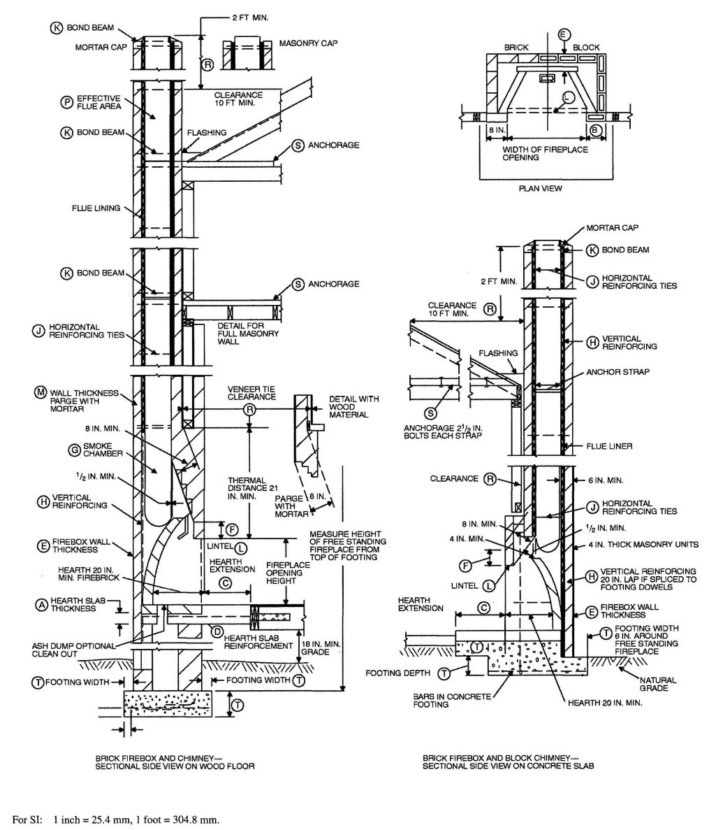
FIGURE R1001.1
FIREPLACE AND CHIMNEY DETAILS
R1001.8 Smoke chamber. Smoke chamber walls shall be constructed of solid masonry units, hollow masonry units grouted solid, stone or concrete. The total minimum thickness of front, back and side walls shall be 8 inches (203 mm) of solid masonry. The inside surface shall be parged smooth with refractory mortar conforming to ASTM C 199. When a lining of firebrick at least 2 inches (51 mm) thick, or a lining of vitrified clay at least 5/8 inch (16 mm) thick, is provided, the total minimum thickness of front, back and side walls shall be 6 inches (152 mm) of solid masonry, including the lining. Firebrick shall conform to ASTM C 1261 and shall be laid with medium duty refractory mortar conforming to ASTM C 199. Vitrified clay linings shall conform to ASTM C 315.
R1001.8.1 Smoke chamber dimensions. The inside height of the smoke chamber from the fireplace throat to the beginning of the flue shall not be greater than the inside width of the fireplace opening. The inside surface of the smoke chamber shall not be inclined more than 45 degrees (0.79 rad) from vertical when prefabricated smoke chamber linings are used or when the smoke chamber walls are rolled or sloped rather than corbeled. When the inside surface of the smoke chamber is formed by corbeled masonry, the walls shall not be corbeled more than 30 degrees (0.52 rad) from vertical.
R1001.9 Hearth and hearth extension. Masonry fireplace hearths and hearth extensions shall be constructed of concrete or masonry, supported by noncombustible materials, and reinforced to carry their own weight and all imposed loads. No combustible material shall remain against the underside of hearths and hearth extensions after construction.
R1001.9.1 Hearth thickness. The minimum thickness of fireplace hearths shall be 4 inches (102 mm).
R1001.9.2 Hearth extension thickness. The minimum thickness of hearth extensions shall be 2 inches (51 mm).
Exception: When the bottom of the firebox opening is raised at least 8 inches (203 mm) above the top of the hearth extension, a hearth extension of not less than 3/8-inch-thick (10 mm) brick, concrete, stone, tile or other approved noncombustible material is permitted.
R1001.10 Hearth extension dimensions. Hearth extensions shall extend at least 16 inches (406 mm) in front of and at least 8 inches (203 mm) beyond each side of the fireplace opening. Where the fireplace opening is 6 square feet (0.6 m2) or larger, the hearth extension shall extend at least 20 inches (508 mm) in front of and at least 12 inches (305 mm) beyond each side of the fireplace opening.
R1001.11 Fireplace clearance. All wood beams, joists, studs and other combustible material shall have a clearance of not less than 2 inches (51 mm) from the front faces and sides of masonry fireplaces and not less than 4 inches (102 mm) from the back faces of masonry fireplaces. The air space shall not be filled, except to provide fire blocking in accordance with Section R1001.12.
Exceptions:
- Masonry fireplaces listed and labeled for use in contact with combustibles in accordance with UL 127 and installed in accordance with the manufacturer’s installation instructions are permitted to have combustible material in contact with their exterior surfaces.
- When masonry fireplaces are part of masonry or concrete walls, combustible materials shall not be in contact with the masonry or concrete walls less than 12 inches (306 mm) from the inside surface of the nearest firebox lining.
- Exposed combustible trim and the edges of sheathing materials such as wood siding, flooring and drywall shall be permitted to abut the masonry fireplace side walls and hearth extension in accordance with Figure R1001.11, provided such combustible trim or sheathing is a minimum of 12 inches (305 mm) from the inside surface of the nearest firebox lining.
- Exposed combustible mantels or trim may be placed directly on the masonry fireplace front surrounding the fireplace opening providing such combustible materials are not placed within 6 inches (152 mm) of a fireplace opening. Combustible material within 12 inches (306 mm) of the fireplace opening shall not project more than 1/8 inch (3 mm) for each 1-inch (25 mm) distance from such an opening.
R1001.12 Fireplace fireblocking. Fireplace fireblocking shall comply with the provisions of Section R602.8.
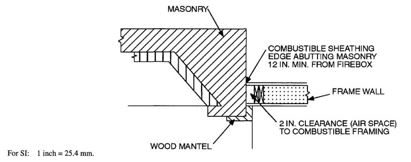
FIGURE R1001.11
CLEARANCE FROM COMBUSTIBLES
R1002.1 Definition. A masonry heater is a heating applianceconstructed of concrete or solid masonry, hereinafter referred to as masonry, which is designed to absorb and store heat from a solid-fuel fire built in the firebox by routing the exhaust gases through internal heat exchange channels in which the flow path downstream of the firebox may include flow in a horizontal or downward direction before entering the chimney and which delivers heat by radiation from the masonry surface of the heater.
R1002.2 Installation. Masonry heaters shall be installed in accordance with this section and comply with one of the following:
R1002.3 Footings and foundation. The firebox floor of a masonry heater shall be a minimum thickness of 4 inches (102 mm) of noncombustible material and be supported on a noncombustible footing and foundation in accordance with Section R1003.2.
R1002.4 Seismic reinforcing. In Seismic Design Categories D0, D1 and D2, masonry heaters shall be anchored to the masonry foundation in accordance with Section R1003.3. Seismic reinforcing shall not be required within the body of a masonry heater whose height is equal to or less than 3.5 times it's body width and where the masonry chimney serving the heater is not supported by the body of the heater. Where the masonry chimney shares a common wall with the facing of the masonry heater, the chimney portion of the structure shall be reinforced in accordance with Section R1003.
R1002.5 Masonry heater clearance. Combustible materials shall not be placed within 36 inches (914 mm) of the outside surface of a masonry heater in accordance with NFPA 211 Section 8-7 (clearances for solid-fuel-burningappliances), and the required space between the heater and combustible material shall be fully vented to permit the free flow of air around all heater surfaces.
Exceptions:
- When the masonry heater wall is at least 8 inches (203 mm) thick of solid masonry and the wall of the heat exchange channels is at least 5 inches (127 mm) thick of solid masonry, combustible materials shall not be placed within 4 inches (102 mm) of the outside surface of a masonry heater. A clearance of at least 8 inches (203 mm) shall be provided between the gas-tight-capping slab of the heater and a combustible ceiling.
- Masonry heaters tested and listed by an American National Standards Association (ANSI)-accredited laboratory to the requirements of UL- 1482 may be installed in accordance with the listing specifications and the manufacturer's written instructions.
R1003.1 Definition. A masonry chimney is a chimney constructed ofsolid masonry units, hollow masonry units grouted solid, stone or concrete, hereinafter referred to as masonry. Masonry chimneys shall be constructed, anchored, supported and reinforced as required in this chapter.
R1003.2 Footings and foundations. Footings for masonry chimneys shall be constructed of concrete or solid masonry at least 12 inches (305 mm) thick and shall extend at least 6 inches (152 mm) beyond the face of the foundation or support wall on all sides. Footings shall be founded on natural undisturbed earth or engineered fill below frost depth. In areas not subjected to freezing, footings shall be at least 12 inches (305 mm) below finished grade.
R1003.3 Seismic reinforcing. Masonry or concrete chimneys shall be constructed, anchored, supported and reinforced as required in this chapter. In all structures regulated by this code assigned to Seismic Design Category C, D0, D1 or D2 masonry and concrete chimneys shall be reinforced and anchored as detailed in Section R1003.3.1, R1003.3.2 and R1003.4. In Seismic Design Category A or B, reinforcement and seismic anchorage is not required.
R1003.3.1 Vertical reinforcing. For chimneys up to 40 inches (1016 mm) wide, four No. 4 continuous vertical bars, anchored in the foundation, shall be placed in the concrete, or between wythes of solid masonry, or within the cells of hollow unit masonry, and grouted in accordance with Section R609.1.1. Grout shall be prevented from bonding with the flue liner so that the flue liner is free to move with thermal expansion. For chimneys more than 40 inches (1016 mm) wide, two additional No. 4 vertical bars shall be installed for each additional 40 inches (1016 mm) in width or fraction thereof.
R1003.3.2 Horizontal reinforcing. Vertical reinforcement shall be placed enclosed within ¼ inch (6 mm) ties, or other reinforcing of equivalent net cross-sectional area, spaced not to exceed 18 inches (457 mm) on center in concrete, or placed in the bed joints of unit masonry, at a minimum of every 18 inches (457 mm) of vertical height. Two such ties shall be installed at each bend in the vertical bars.
R1003.4 Seismic anchorage. Masonry and concrete chimneys and foundations in all structures regulated by this code assigned to Seismic Design Category C, D0, D1 or D2 shall be anchored at each floor, ceiling or roof line more than 6 feet (1829 mm) above grade, except where constructed completely within the walls. Anchorage shall conform to the requirements in Section R1003.4.1.
R1003.4.1 Anchorage. Two 3/16-inch by 1-inch (5 mm by 25 mm) straps shall be embedded a minimum of 12 inches (305 mm) into the chimney. Straps shall be hooked around the outer bars and extend 6 inches (152 mm) beyond the bend. Each strap shall be fastened to a minimum of four floor joists with two ½-inch (13 mm) bolts.
R1003.5 Corbeling. Masonry chimneys shall not be corbeled more than one-half of the chimney's wall thickness from a wall or foundation, nor shall a chimney be corbeled from a
511wall or foundation is less than 12 inches (305 mm) thick unless it projects equally on each side of the wall, except that on the second story of a two-story dwelling, corbeling of chimneys on the exterior of the enclosing walls may equal the wall thickness. The projection of a single course shall not exceed one-half the unit height or one-half of the unit bed depth, whichever is less.
R1003.6 Changes in dimension. The chimney wall or chimney flue lining shall not change in size or shape within 6 inches (152 mm) above or below where the chimney passes through floor components, ceiling components or roof components.
R1003.7 Offsets. Where a masonry chimney is constructed with a fireclay liner surrounded by one wy the of masonry, the maximum offset shall be such that the centerline of the flue above the offset does not extend beyond the center of the chimney wall below the offset. Where the chimney offset is supported by masonry below the offset in an approved manner, the maximum offset limitations shall not apply. Each individual corbeled masonry course of the offset shall not exceed the projection limitations specified in Section R1003.5.
R1003.8 Additional load. Chimneys shall not support loads other than their own weight unless they are designed and constructed to support the additional load. Construction of masonry chimneys as part of the masonry walls or reinforced concrete walls of the building shall be permitted.
R1003.9 Termination. Chimneys shall extend at least 2 feet (610 mm) higher than any portion of a building within 10 feet (3048 mm), but shall not be less than 3 feet (914 mm) above the highest point where the chimney passes through the roof.
R1003.9.1 Spark arrestors. All chimneys attached to any appliance or fireplace that burns solid fuel shall be equipped with an approved spark arrester. The spark arrestor shall meet all of the following requirements:
R1003.10 Wall thickness. Masonry chimney walls shall be constructed ofsolid masonry units or hollow masonry units grouted solid with not less than a 4-inch (102 mm) nominal thickness.
R1003.10.1 Masonry veneer chimneys. Where masonry is used to vaneer a frame chimney, through-flashing and weep holes shall be installed as required by Section R703.
R1003.11 Flue lining (material). Masonry chimneys shall be lined. The lining material shall be appropriate for the type of appliance connected, according to the terms of the appliance listing and manufacturer's instructions.
R1003.11.1 Residential-type appliances (general). Flue lining systems shall comply with one of the following:
R1003.11.2 Flue linings for specific appliances. Flue linings other than these covered in Section R1003.11.1, intended for use with specific types of appliances, shall comply with Sections R1003.11.3 through R1003.11.6.
R1003.11.3 Gas appliances. Flue lining systems for gas appliances shall be in accordance with the California Mechanical Code.
R1003.11.4 Pellet fuel-burning appliances. Flue lining and vent systems for use in masonry chimneys with pellet fuel-burning appliances shall be limited to the following:
R1003.11.5 Oil-fired appliances approved for use with Type L vent. Flue lining and vent systems for use in masonry chimneys with oil-fired appliances approved for use with Type L vent shall be limited to the following:
R1003.11.6 Notice of usage. When a flue is relined with a material not complying with Section R1003.11.1, the chimney shall be plainly and permanently identified by a label attached to a wall, ceiling or other conspicuous location adjacent to where the connector enters the chimney. The label shall include the following message or equivalent language:
THIS CHIMNEY FLUE IS FOR USE ONLY WITH [TYPE OR CATEGORY OF APPLIANCE] APPLIANCES THAT BURN [TYPE OF FUEL]. DO NOT CONNECT OTHER TYPES OF APPLIANCES.
R1003.12 Clay flue lining (installation). Clay flue liners shall be installed in accordance with ASTM C 1283 and extend from a point not less than 8 inches (203 mm) below the lowest inlet or, in the case of fireplaces, from the top of the smoke chamber to a point above the enclosing walls. The lining shall be carried up vertically, with a maximum slope no greater than 30 degrees (0.52 rad) from the vertical.
Clay flue liners shall be laid in medium-duty water insoluble refractory mortar conforming to ASTM C 199 with tight mortar
512joints left smooth on the inside and installed to maintain an air space or insulation not to exceed the thickness of the flue liner separating the flue liners from the interior face of the chimney masonry walls. Flue liners shall be supported on all sides. Only enough mortar shall be placed to make the joint and hold the liners in position.
R1003.12.1 Listed materials. Listed materials used as flue linings shall be installed in accordance with the terms of their listings and manufacturer's instructions.
R1003.12.2 Space around lining. The space surrounding a chimney lining system or vent installed within a masonry chimney shall not be used to vent any other appliance.
Exception: This shall not prevent the installation of a separate flue lining in accordance with the manufacturer's installation instructions.
R1003.13 Multiple flues. When two or more flues are located in the same chimney, masonry wythes shall be built between adjacent flue linings. The masonry wythes shall be at least 4 inches (102 mm) thick and bonded into the walls of the chimney.
Exception: When venting only one appliance, two flues may adjoin each other in the same chimney with only the flue lining separation between them. The joints of the adjacent flue linings shall be staggered at least 4 inches (102 mm).
R1003.14 Flue area (appliance). Chimney flues shall not be smaller in area than of the area of the connector from the appliance [see Table R1003.14(1) and R1003.14(2)]. The sizing of a chimney flue to which multiple appliance venting systems are connected shall be in accordance with the California Mechanical Code.
R1003.15 Flue area (masonry fireplace). Flue sizing for chimneys serving fireplaces shall be in accordance with Section R1003.15.1 or Section R1003.15.2.
R1003.15.1 Option 1. Round chimney flues shall have a minimum net cross-sectional area of at least 1⁄12 of the fireplace opening. Square chimney flues shall have a minimum net cross-sectional area of 1⁄10 of the fireplace opening. Rectangular chimney flues with an aspect ratio less than 2 or 1 shall have a minimum net cross-sectional area of 1⁄10 of the fireplace opening. Rectangular chimney flues with an aspect ratio of 2 or 1 or more shall have a minimum net cross-sectional area of 1⁄12; of the fireplace opening. Cross-sectional areas of clay flue linings are shown in Tables R1001.14(1) and R1001.14(2) or as provided by the manufacturer or as measured in the field.
R1003.15.2 Option 2. The minimum net cross-sectional area of the chimney flue shall be determined in accordance with Figure R1003.15.2. A flue size providing at least the equivalent net cross-sectional area shall be used. Cross-sectional areas of clay flue linings are shown in Tables R1003.14(1) and R1003.14(2) or as provided by the manufacturer or a measured in the field. The height of the chimney shall be measured from the firebox floor to the top of the chimney flue.
| FLUE SIZE, INSIDE DIAMETER (inches) | CROSS–SECTIONAL AREA (square inches) |
|---|---|
| For SI: 1 inch = 25.4 mm, 1 square inch = 645.16 mm2. | |
| a. Flue sizes are based on ASTM C 315. | |
| 6 | 28 |
| 7 | 38 |
| 8 | 50 |
| 10 | 78 |
| 10¾ | 90 |
| 12 | 113 |
| 15 | 176 |
| 18 | 254 |
| FLUE SIZE, OUTSIDE NOMINAL DIMENSIONS (inches) | CROSS–SECTIONAL AREA (square inches) |
|---|---|
| For SI: 1 inch = 25.4 mm, 1 square inch = 645.16 mm2. | |
| 4.5 × 8.5 | 23 |
| 4.5 × 13 | 34 |
| 8 × 8 | 42 |
| 8.5 × 8.5 | 49 |
| 8 × 12 | 67 |
| 8.5 × 13 | 76 |
| 12 × 12 | 102 |
| 8.5 × 18 | 101 |
| 13 × 13 | 127 |
| 12 × 16 | 131 |
| 13 × 18 | 173 |
| 16 × 16 | 181 |
| 16 × 20 | 222 |
| 18 × 18 | 233 |
| 20 × 20 | 298 |
| 20 × 24 | 335 |
| 24 × 24 | 431 |
R1003.16 Inlet. Inlets to masonry chimneys shall enter from the side. Inlets shall have a thimble of fireclay, rigid refractory material or metal that will prevent the connector from pulling out of the inlet or from extending beyond the wall of the liner.
513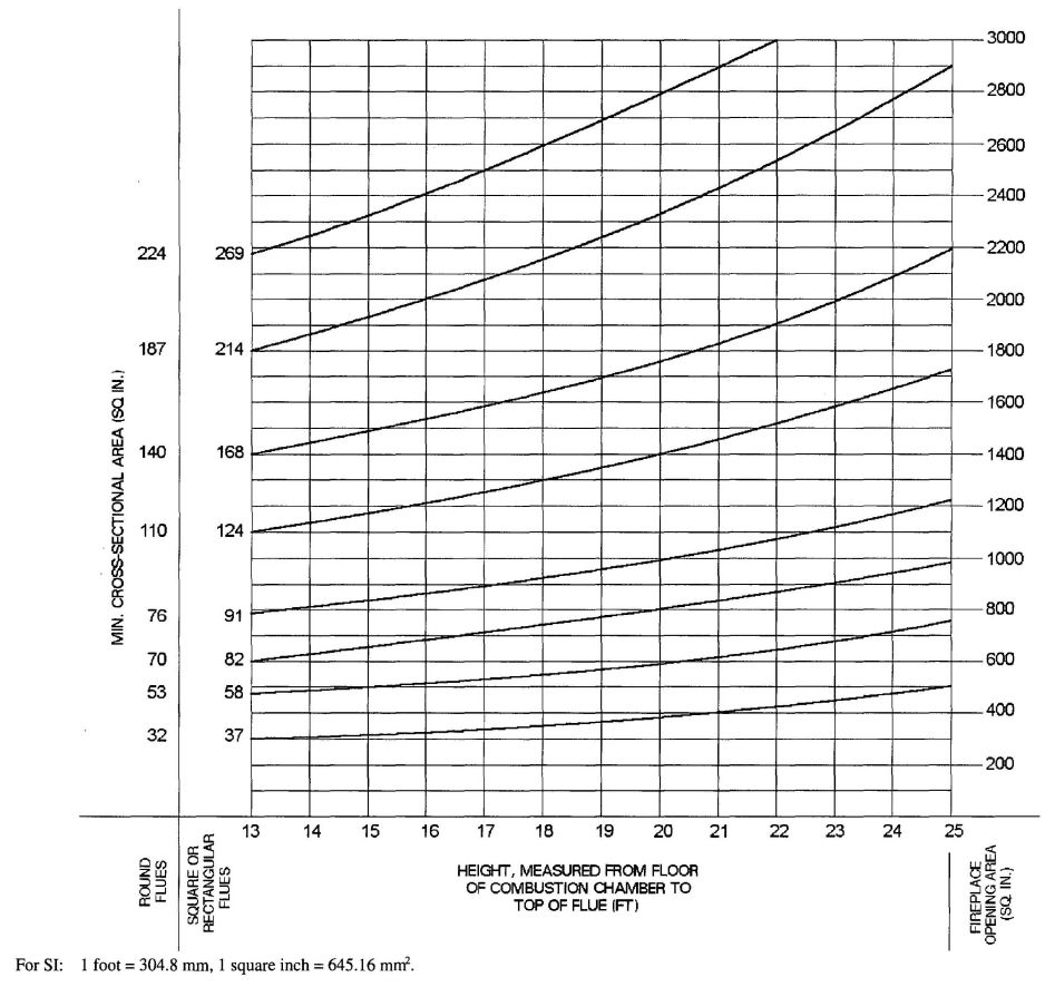
FIGURE R1003.15.2
FLUE SIZES FOR MASONRY CHIMNEYS
R1003.17 Masonry chimney cleanout openings. Cleanout openings shall be provided within 6 inches (152 mm) of the base of each flue within every masonry chimney. The upper edge of the cleanout shall be located at least 6 inches (152 mm) below the lowest chimney inlet opening. The height of the opening shall be at least 6 inches (152 mm). The cleanout shall be provided with a noncombustible cover.
Exception: Chimney flues serving masonry fireplaces where cleaning is possible through the fireplace opening.
R1003.18 Chimney clearances. Any portion of a masonry chimney located in the interior of the building or within the exterior wall of the building shall have a minimum air space clearance to combustibles of 2 inches (51 mm). Chimneys located entirely outside the exterior walls of the building, including chimneys that pass through the soffit or cornice, shall have a minimum air space clearance of 1 inch (25 mm). The air space shall not be filled, except to provide fire blocking in accordance with Section R1003.19.
Exceptions:
R1003.19 Chimney fireblocking. All spaces between chimneys and floors and ceilings through which chimneys pass shall be fireblocked with noncombustible material securely fastened in place. The fireblocking of spaces between chimneys and wood joists, beams or headers shall be self-supporting or be placed on strips of metal or metal lath laid across the spaces between combustible material and the chimney.
R1003.20 Chimney crickets. Chimneys shall be provided with crickets when the dimension parallel to the ridgeline is greater than 30 inches (762 mm) and does not intersect the ridgeline. The intersection of the cricket and the chimney shall be flashed and counterflashed in the same manner as normal roof-chimney intersections. Crickets shall be constructed in compliance with Figure R1003.20 and Table R1003.20.
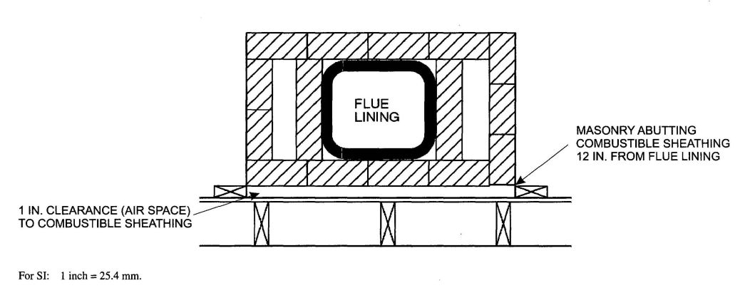
FIGURE R1003.18
CHIMNEY CLEARANCE FROM COMBUSTIBLES
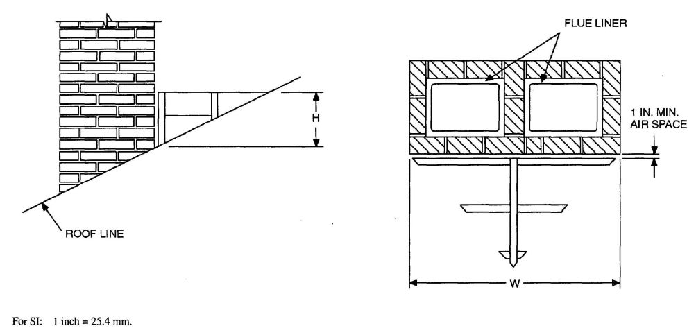
FIGURE R1003.20
CHIMNEY CRICKET
| ROOF SLOPE | H |
|---|---|
| 12–12 | ½ of W |
| 8–12 | 1/3 of W |
| 6–12 | ¼ of W |
| 4–12 | 1/6 of W |
| 3–12 | 1/8 of W |
R1004.1 General. Factory-built fireplaces shall be listed and labeled and shall be installed in accordance with the conditions of the listing. Factory-built fireplaces shall be tested in accordance with UL 127.
R1004.2 Hearth extensions. Hearth extensions of approved factory-built fireplaces shall be installed in accordance with the listing of the fireplace. The hearth extension shall be readily distinguishable from the surrounding floor area.
R1004.3 Decorative shrouds. Decorative shrouds shall not be installed at the termination of chimneys for factory-built fireplaces except where the shrouds are listed and labeled for use with the specific factory-built fireplaces system and installed in accordance with the manufacturer’s installation instructions.
R1004.4 Unvented gas log heaters. An unvented gas log heater shall not be installed in a factory-built fireplace unless the fireplace system has been specifically tested, listed and labeled for such use in accordance with UL 127.
R1005.1 Listing. Factory-built chimneys shall be listed and labeled and shall be installed and terminated in accordance with the manufacturer’s installation instructions.
R1005.2 Decorative shrouds. Decorative shrouds shall not be installed at the termination of factory-built chimneys except where the shrouds are listed and labeled for use with the specific factory-built chimney system and installed in accordance with the manufacturer’s installation instructions.
R1005.3 Solid-fuel appliances. Factory-built chimneys installed in dwelling units with solid-fuel-burning appliances shall comply with the Type HT requirements of UL 103 and shall be marked “Type HT and “Residential Type and Building Heating Appliance Chimney.”
Exception: Chimneys for use with open combustion chamber fireplaces shall comply with the requirements of UL 103 and shall be marked “Residential Type and Building Heating Appliance Chimney.”
Chimneys for use with open combustion chamber appliances installed in buildings other than dwelling units shall comply with the requirements of UL 103 and shall be marked “Building Heating Appliance Chimney” or “Residential Type and Building Heating Appliance Chimney.”
R1005.4 Factory-built fireplaces. Chimneys for use with factory-built fireplaces shall comply with the requirements of UL 127.
R1005.5 Support. Where factory-built chimneys are supported by structural members, such as joists and rafters, those members shall be designed to support the additional load.
R1005.6 Medium-heat appliances. Factory-built chimneys for medium-heat appliances producing flue gases having a temperature above 1,000°F (538°C), measured at the entrance to the chimney shall comply with UL 959.
R1006.1 Exterior air. Factory-built or masonry fireplaces covered in this chapter shall be equipped with an exterior air supply to assure proper fuel combustion unless the room is mechanically ventilated and controlled so that the indoor pressure is neutral or positive.
R1006.1.1 Factory-built fireplaces. Exterior combustion air ducts for factory-built fireplaces shall be a listed component of the fireplace and shall be installed according to the fireplace manufacturer’s instructions.
R1006.1.2 Masonry fireplaces. Listed combustion air ducts for masonry fireplaces shall be installed according to the terms of their listing and the manufacturer’s instructions.
R1006.2 Exterior air intake. The exterior air intake shall be capable of supplying all combustion air from the exterior of the dwelling or from spaces within the dwelling ventilated with outside air such as nonmechanically ventilated crawl or attic spaces. The exterior air intake shall not be located within the garage or basement of the dwelling nor shall the air intake be located at an elevation higher than the firebox. The exterior air intake shall be covered with a corrosion-resistant screen of ¼-inch (6 mm) mesh.
R1006.3 Clearance. Unlisted combustion air ducts shall be installed with a minimum 1-inch (25 mm) clearance to combustibles for all parts of the duct within 5 feet (1524 mm) of the duct outlet.
R1006.4 Passageway. The combustion air passageway shall be a minimum of 6 square inches (3870 mm2) and not more than 55 square inches (0.035 m2), except that combustion air systems for listed fireplaces shall be constructed according to the fireplace manufacturer’s instructions.
R1006.5 Outlet. Locating the exterior air outlet in the back or sides of the firebox chamber or within 24 inches (610 mm) of the firebox opening on or near the floor is permitted. The outlet shall be closable and designed to prevent burning material from dropping into concealed combustible spaces.
(Note: Part IV is not adopted. See California Energy Code, Title 24, Part 6.)
517 518(Note: Part V is not adopted. See California Mechanical Code, Title 24, Part 4.)
519 520(Note: Part VI is not adopted. See California Mechanical Code and California Plumbing Code, Title 24, Parts 4 and 5.)
521 522(Note: Part VII is not adopted. See California Plumbing Code, Title 24, Part 5.)
523 524(Note: Part VIII is not adopted. See California Electrical Code, Title 24, Part 3.)
525 526| Adopting agency | BSC | SFM | HCD | DSA | OSHPD | CSA | DPH | AGR | DWR | CEC | CA | SL | SLC | ||||||
|---|---|---|---|---|---|---|---|---|---|---|---|---|---|---|---|---|---|---|---|
| 1 | 2 | 1-AC | AC | SS | 1 | 2 | 3 | 4 | |||||||||||
| Adopt entire chapter | |||||||||||||||||||
| Adopt entire chapter as amended (amended sections listed below) |
X | X | X | ||||||||||||||||
| Adopt only those sections that are listed below |
|||||||||||||||||||
| Chapter/Section | |||||||||||||||||||
| ANSI | X | ||||||||||||||||||
| ASTM | X | ||||||||||||||||||
| ICC | X | ||||||||||||||||||
| NFPA | X | ||||||||||||||||||
| NFPA 720-09 | X | X | |||||||||||||||||
| SFM | X | ||||||||||||||||||
| UBC | X | ||||||||||||||||||
Notwithstanding California laws and regulations, these referenced standards shall be applicable only to those California Residential Code sections that are adopted.
| AAMA | American Architectural Manufacturers Association 1827 Walden Office Square, Suite 550 Schaumburg, IL 60173 |
|
| Standard reference number | Title | Referenced in code section number |
| AAMA/WDMA/CSA 101/I.S.2/A440—08 | North American Fenestration Standards/Specifications for Windows, Doors and Skylights | N1102.4.4, R308.6.9, R613.6 |
| 450—06 | Voluntary Performance Rating Method for Mulled Fenestration Assemblies | R612.11.1 |
| 506—06 | Voluntary Specifications for Hurricane Impact and Cycle Testing of Fenestration Products | R612.9.1 |
| 711—07 | Voluntary Specification for Self Adhering Flashing Used for Installation of Exterior Wall Fenestration Products | R703.8 |
| ACI | American Concrete Institute 38800 Country Club Drive Farmington Hills, MI 48331 |
|
| 318—08 | Building Code Requirements for Structural Concrete | R301.2.2.2.4,R301.2.2.3.4, R402.2, R404.1.2, Table 404.1.2(5), Table R404.1.2(6), Table R404.1.2(7), Table R404.1.2(8), Table R404.1.2(9), R404.1.2.1, R404.1.2.3, R404.1.2.4, R404.1.4.2, R404.6.1, R611.1, R611.1.1, R611.1.2, R611.2, R611.5.1, R611.8.2, R611.9.2, R611.9.3. |
| 332—08 | Code Requirements for Residential Concrete Construction | R402.2, R403.1, R404.1.2, R404.1.2.4, R404.1.4.2 |
| 530—08 | Building Code Requirements for Masonry Structures | R404.1.1, R606.1, R606.1.1, R606.12.1, R606.12.2.2.1, R606.12.2.2.2, R606.12.3.1, Table R703.4 |
| 530.1—08 | Specification for Masonry Structures | R404.1.1, R606.1, R606.1.1, R606.12.1, R606.12.2.2.1, R606.12.2.2.2, R606.12.3.1, Table R703.4 |
| ACCA | Air Conditioning Contractors of America 2800 Shirlington Road, Suite 300 Arlington, VA 22206 |
|
| Manual D—95 | Residential Duct Systems | M1601.1, M1602.2 |
| Manual J—02 | Residential Load Calculation—Eighth Edition | M.1401.3 |
| Manual S—04 | Residential Equipment Selection | M1401.3 |
| AFPA | American Forest and Paper Association 1111 19th Street, NW, Suite 800 Washington, DC 20036 |
|
| NDS—05 | National Design Specification (NDS) for Wood Construction —with 2005 Supplement | R404.2.2, R502.2, Table R503.1, R602.3, Table R602.3.1 R611.9.2, R611.9.3, R802.2, |
| WFCM—08 | Wood Frame Construction Manual for One-and Two- family Dwellings | R301.1.1, R301.2.1.1, R602.10.6.2, R611.9.2, R611.9.3, R611.10 |
| AFPA—93 | Span Tables for Joists and Rafters | R502.3, R802.4, R802.5 |
| PWF—07 | Permanent Wood Foundation Design Specification | R401.1, R404.2.3 |
| AISI | American Iron and Steel Institute 1140 Connecticut Ave, Suite 705 Washington, DC 20036 |
|
| AISI S100—07 | North American Specification for the Design of Cold-formed Steel Structural Members | R505.1.3, R603.6, R6.11.9.2, R611.9.3, R804.3.7 |
| AISI S230—07 | Standard for Cold-formed Steel Framing-prescriptive Method for One-and Two-family Dwellings | R301.1.1, R301.2.1.1, R301.2.2.3.1, R301.2.2.3.5, R603.6, R611.9.2, R611.9.3, R611.10 |
| AITC | American Institute of Timber Construction 7012 S. Revere Parkway, Suite 140 Centennial, CO 80112 |
|
| ANSI/AITC A 190.1—07 | Structural Glued Laminated Timber | R502.1.5, R602.1.2, R802.1.4 |
| ANSI | American National Standards Institute 25 West 43 rd Street, Fourth Floor New York, NY 10036 |
|
| A108.1A—99 | Installation of Ceramic Tile in the Wet-set Method, with Portland Cement Mortar | R702.4.1 |
| A108.1B—99 | Installation of Ceramic Tile, Quarry Tile on a Cured Portland Cement Mortar Setting Bed with Dry-set or Latex-Portland Mortar | R702.4.1 |
| A108.4—99 | Installation of Ceramic Tile with Organic Adhesives or Water Cleanable Tile-setting Epoxy Adhesive | R702.4.1 |
| A 108.5—99 | Installation of Ceramic Tile with Dry-set Portland Cement Mortar or Latex-Portland Cement Mortar | R702.4.1 |
| A 108.6—99 | Installation of Ceramic Tile with Chemical-resistant, Water-cleanable Tile-setting and grouting Epoxy | R702.4.1 |
| A108.11—99 | Interior Installation of Cementitious Backer Units | R702.4.1 |
| A118.1—99 | American National Standard Specifications for Dry-set Portland Cement Mortar | R702.4.1 |
| A118.3—99 | American National Standard Specifications for Chemical-resistant, Water-cleanable Tile-setting and Grouting Epoxy and Water-cleanable Tile-setting Epoxy Adhesive | R702.4.1 |
| A118.10—99 | Specification for Load Bearing, Bonded, Waterproof Membranes for Thin-set Ceramic Tile and Dimension Stone Installation | P2709.2 |
| A136.1—99 | American National Standard Specifications for Organic Adhesives for Installation of Ceramic Tile | R702.4.1 |
| A137.1—88 | American National Standard Specifications for Ceramic Tile | R702.4.1 |
| A208.1—99 | Particleboard | R503.3.1, R605.1 |
| LC1—97 | Interior Fuel Gas Piping Systems Using Corrugated Stainless Steel Tubing —with Addenda LC la-1999 and LC 1b-2001 | G2414.5.3 |
| LC4—07 | Press-connect Copper and Copper Alloy Fittings for use in Fuel Gas Distribution Systems | G2414.10.2 |
| S3.41 | American National Standard Audible Evacuation Signal | R325.5.2.1 |
| Z21.1—03 | Household Cooking Gas Appliances—with Addenda Z21.1a-2003 and Z21.1b-2003 | G2447.1 |
| Z21.5.1—02 | Gas Clothes Dryers—Volume I—Type I Clothes Dryers—with Addenda Z21.5.1a-2003 | G2438.1 |
| Z21.8—94 (R2002) | Installation of Domestic Gas Conversion Burners | G2443.1 |
| Z21.10.1—04 | Gas Water Heaters—Volume I—Storage Water Heaters with Input Ratings of 75,000 Btu per hour or Less | G2448.1 |
| Z21.10.3—01 | Gas Water Heaters—Volume III—Storage Water Heaters with Input Ratings above 75,000 Btu per hour, Circulating and Instantaneous Water Heaters—with Addenda Z21.10.3a-2003 and Z21.10.3b-2004 | G2448.1 |
| Z21.11.2—02 | Gas-fired Room Heaters—Volume II—Unvented Room Heaters—with Addenda Z21.11.2a-2003 | G2445.1 |
| Z21.13—04 | Gas-fired Low-Pressure Steam and Hot Water Boilers | G2452.1 |
| Z21.15—97 (R2003) | Manually Operated Gas Valves for Appliances, Appliance Connector Valves and Hose End Valves—with Addenda Z21.15a-2001 (R2003) | Table G2420.1.1 |
| Z21.22—99 (R2003) | Relief Valves for Hot Water Supply Systems—with Addenda Z21.22a-2000 (R2003)and 21.22b-2001 (R2003) | P2803.2, P2803.7 |
| Z21.24-97 | Connectors for Gas Appliances | G2422.1 |
| Z21.40.1—96 (R2002) | Gas-fired Heat-activated Air Conditioning and Heat Pump Appliances— with Z21.40. 1a-97 (R2002) | G2449.1 |
| Z21.40.2—96 (R2002) | Gas-fired, Work-activated Air Conditioning and Heat Pump Appliances (Internal Combustion) —with Z21.40.2a-1997 (R2002) | G2449.1 |
| Z21.42—93 (R2002) | Gas-fired Illuminating Appliances | G2450.1 |
| Z21.47—03 | Gas-fired Central Furnaces | G2442.1 |
| Z21.50—03 | Vented Gas Fireplaces—with Addenda Z21.50a-2003 | G2434.1 |
| Z21.56—01 | Gas-fired Pool Heaters—with Addenda Z21.56a-2004 and Z21.56b—2004 | G2441.1 |
| Z21.58—95 (R2002) | Outdoor Cooking Gas Appliances—with Addenda Z21.58a-1998 (R2002) and Z21.58b-2002 | G2447.1 |
| Z21.60—03 | Decorative Gas Appliances for Installation in Solid Fuel Burning Fireplaces— with Addenda Z21.60a-2003 | G2432.1 |
| Z21.75/CSA 6.27—01 | Connectors for Outdoor Gas Appliances | G2422.1 |
| Z21.80—03 | Line Pressure Regulators | G2421.1 |
| Z21.83—98 | Fuel Cell Power Plants. | M1903.1 |
| Z21.84—02 | Manually Listed, Natural Gas Decorative Gas Appliances for Installation in SolidFuelburning Fireplaces—with Addenda Z21.84a-2003 | G2432.1, G2432.2 |
| Z21.86—04 | Gas-fired Vented Space Heating Appliances | G2436.1, G2437.1, G2446.1 |
| Z21.88—02 | Vented Gas Fireplace Heaters—with Addenda A21.88a-2003 and Z21.88b—2004 | G2435.1 |
| Z21.91—01 | Ventless Firebox Enclosures for Gas-fired Unvented Decorative Room Heaters | G2445.7.1 |
| Z83.6—90 (R1998) | Gas-fired Infrared Heaters | G2451.1 |
| Z83.8—02 | Gas-fired Unit Heaters and Gas-fired Duct Furnaces—with Addenda Z83.8a-2003 | G2444.1 |
| Z97.1—04 | Safety Glazing Materials Used in Buildings—Safety Performance Specifications and Methods of Test | R308.1.1, R308.3.1 |
| Z124.1—95 | Plastic Bathtub Units | Table P2701.1 |
| Z124.2—95 | Plastic Shower Receptors and Shower Stalls | Table P2701.1 |
| Z124.3—95 | Plastic Lavatories | Table P2701.1, P2711.1, P2711.2 |
| Z124.4—96 | Plastic Water Closet Bowls and Tanks | Table P2701.1, P2712.1 |
| Z124.6—97 | Plastic Sinks | Table P2701.1 |
| APA | APA-The Engineered Wood Association 7011 South 19th Tacoma, WA 98466 |
|
| APA E30—03 | Engineered Wood Construction Guide | Table R503.2.1.1(1), R503.2.2, R803.2.2, R803.2.3 |
| APSP | The Association of Pool & Spa Professionals 2111 Eisenhower Avenue Alexandria, VA 22314 |
|
| ANSI/APSP7—06 | Standard for Suction Entrapment Avoidance in Swimming Pools Wading Pools, Spas, Hot Tubs and Catch Basins | AG106.1 |
| ANSI/NSPI 3—99 | Standard for Permanently Installed Residential Spas | AG104.1 |
| ANSI/NSPI 4—99 | Standard for Above-ground/On-ground Residential Swimming Pools | AG103.2 |
| ANSI/NSPI-5—2003 | Standard for Residential In-ground Swimming Pools | AG103.1 |
| ANSI/NSPI 6—99 | Standard for Residential Portable Spas | AG104.2 |
| ASCE/SEI | American Society of Civil Engineers Structural Engineering Institute 1801 Alexander Bell Drive Reston, VA 20191 |
|
| 5—08 | Building Code Requirements for Masonry Structures | R404.1.1, R606.1, R606.1.1, R606.12.1, R606.12.2.2.1, R606.12.2.2.2, R606.12.3.1, Table R703.4 |
| 6—08 | Specification for Masonry Structures | R404.1.1, R606.1, R606.1.1, R606.12.1, R606.12.2.2.1, R606.12.2.2.2, R606.12.3.1, Table R703.4 |
| 7—05 | Minimum Design Loads for Buildings and Other Structures | R301.2.1.1, R301.2.1.2, R301.2.1.5, R301.2.1.5.1, R301.2.4.1, Table R611.6(1), Table R611.6(2), Table R611.6(3), Table R611.6(4), Table R611.7(1A), R611.9.2, R611.9.3, Table R802.11, AH107.4.3. |
| 24—05 | Flood-resistant Design and Construction | R301.2.4, R301.2.4.1, R322.1, R322.1.1, R322.1.6, R322.1.9, R322.2.2, AG103.3 |
| 32—01 | Design and Construction of Frost-protected Shallow Foundation | R403.1.4.1 |
| ASHRAE | American Society of Heating, Refrigerating and Air-Conditioning Engineers, Inc. 1791 Tullie Circle, NE Atlanta, GA 30329 |
|
| 34—2004 | Designation and Safety Classification of Refrigerants | M1411.1 |
| ASHRAE—2005 | ASHRAE Fundamentals Handbook—2005 | N1102.1.3, P3001.2, P3101.4, P3103.2 |
| ASME | American Society of Mechanical Engineers Three Park Avenue New York, NY 10016-5990 |
|
| A17.1/CSA B44—2007 | Safety Code for Elevators and Escalators | R321.1 |
| A18.1—2005 | Safety Standard for Platforms and Stairway Chair Lifts | R321.2 |
| A112.1.2—2004 | Air Gaps in Plumbing Systems | Table P2902.3, P2902.3.1 |
| A112.1.3—2000 (Reaffirmed 2005) | Air Gap Fittings for Use with Plumbing Fixtures, Appliances and Appurtenances | Table P2701.1, P2902.3.1 |
| A112.3.1—2007 | Stainless Steel Drainage Systems for Sanitary, DWV, Storm and Vacuum Applications Above and Below Ground | Table P3002.1(1), Table P3002.1(2), Table P3002.2, Table P3002.3, Table P3302.1 |
| A112.3.4—2000 (R2004) | Macerating Toilet Systems and Related Components | Table P2701.1, P3007.5 |
| A112.4.1—1993 (R2002) | Water Heater Relief Valve Drain Tubes | P2803.6.2 |
| A112.4.3—1999 (R2004) | Plastic Fittings for Connecting Water Closets to the Sanitary Drainage System | P3003.19 |
| A112.6.1M—1997 (R2002) | Floor Affixed Supports for Off-the floor Plumbing Fixtures for Public Use | Table P2701.1, P2702.4 |
| A112.6.1—2000 (R2004) | Framing-affixed Supports for Off-the-floor Water Closets with Concealed Tanks | Table P2701.1, P2702.4 |
| A112.6.3—2001 (R2007) | Floor and Trench Drains | Table P2701.1 |
| A112.14.1—03 | Backwater Valves | P3008.2 |
| A112.18.1—2005/ CSA B125.1-2005 | Plumbing Supply Fittings | Table P2701.1, P2708.4, P2722.1, P2902.2 |
| A112.18.2—2005/CSA B125.2-2005 | Plumbing Waste Fittings | Table P2701.1, P2702.2 |
| A112.18.3—2002 | Performance Requirements for Backflow Protection Devices and Systems in Plumbing Fixture Fittings | P2708.4, P2722.3 |
| A112.18.6—2003 | Flexible Water Connectors | P2905.7 |
| A112.19.1M—1994 (R2004) | Enameled Cast Iron Plumbing Fixtures—with 1998 and 2000 Supplements | Table P2701.1, P2711.1 |
| A112.19.2—2003 | Vitreous China Plumbing Fixtures—and Hydraulic Requirements for Water Closets and Urinals | Table P2701.1, P2705.1, P2711.1, P2712.1, P2712.2 |
| A112.19.3M—2000 (R2007) | Stainless Steel Plumbing Fixtures (Designed for Residential Use)— with 2002 Supplement | Table P2701.1, P2705.1, P2711.1 |
| A112.19.4M—1994 (R2004) | Porcelain Enameled Formed Steel Plumbing Fixtures—with 1998 and 2000 Supplements | Table P2701.1, P2711.1 |
| A112.19.5—2005 | Trim for Water-closet Bowls, Tanks and Urinals | Table P2701.1 |
| A112.19.6—1995 | Hydraulic Performance Requirements for Water Closets and Urinals | P2712.1, P2712.2 |
| A112.19.7M—2006 | Hydromassage Bathtub Appliances | Table P2701.1 |
| A112.19.8M—1987 (R1996) | Suction Fittings for Use in Swimming Pools, Wading Pools, Spas, Hot Tubs and Whirlpool Bathtub Appliances | Table P2701.1 |
| A112.19.9M—1991 (R2002) | Nonvitreous Ceramic Plumbing Fixtures—with 2002 Supplement | Table P2701.1, P27.11.1, P2712.1 |
| A112.19.12—2006 | Wall-mounted and Pedestal-mounted, Adjustable and Pivoting Lavatory and Sink Carrier Systems | Table P2701.1, P2711.4, P2714.2 |
| A112.19.13—2001 (R2007) | Electrohydraulic Water Closets | P2712.9 |
| A112.19.15—2005 | Bathtub/Whirlpool Bathtubs with Pressure Sealed Doors | Table P2701.1, P2713.2 |
| B1.20.1—1983 (R2006) | Pipe Threads, General Purpose (Inch) | G2414.9, P3003.3.3, P3003.5.3, P3003.10.4, P3003.12.1, P3003.14.3 |
| B16.3—2006 | Malleable-iron-threaded Fittings Classes 150 and 300 | Table P2905.6 |
| B16.4—2006 | Gray-iron-threaded Fittings Classes 125 and 250 | Table P2905.6, Table P3002.3 |
| B16.9—2003 | Factory-made Wrought Steel Buttwelding Fittings | Table P2905.6 |
| B16.11—2005 | Forged Fittings, Socket-welding and Threaded | Table P2905.6 |
| B16.12—1998 | Cast-iron-threaded Drainage Fittings | Table P2905.6, Table P3002.3 (R2006) |
| B16.15—2006 | Cast-bronze-threaded Fittings | Table P2905.6, Table P3002.3 |
| B16.18—2001 (R2005) | Cast Copper Alloy Solder Joint Pressure Fittings | Table P2905.6, Table P3002.3 |
| B16.22—2001 (R2005) | Wrought Copper and Copper Alloy Solder Joint Pressure Fittings | Table P2905.6, Table P3002.3 |
| B16.23—2002 (R2006) | Cast Copper Alloy Solder Joint Drainage Fittings (DWV) | Table P2905.6, Table P3002.3 |
| B16.26—2006 | Cast Copper Alloy Fittings for Flared Copper Tubes | Table P2905.6, Table P3002.3 |
| B16.28—1994 | Wrought Steel Buttwelding Short Radius Elbows and Returns | Table P2905.6 |
| B16.29—2001 | Wrought Copper and Wrought Copper Alloy Solder Joint Drainage Fittings (DWV) | Table P2905.6, Table P3002.3 |
| B16.33—2002 (R2006) | Manually Operated Metallic Gas Valves for Use in Gas Piping Systems up to 125 psig (Sizes ½ through 2) | Table G2420.1.1 |
| B16.44—02 | Manually Operated Metallic Gas Valves For Use in Above-ground Piping Systems up to 5 psi | Table G2420.1.1 |
| B36.10M—2004 | Welded and Seamless Wrought-steel Pipe | G2414.4.2 |
| BPVC—2004 | ASME Boiler and Pressure Vessel Code | G2452.1, M2001.1.1 |
| CSD-1—2004 | Controls and Safety Devices for Automatically Fired Boilers | G2452.1, M2001.1.1 |
| ASSE | American Society of Sanitary Engineering 901 Canterbury, Suite A Westlake, OH 44145 |
|
| 1001—02 | Performance Requirements for Atmospheric-type Vacuum Breakers | Table P2902.3, P2902.3.2 |
| 1002—99 | Performance Requirements for Antisiphon Fill Valves (Ballcocks) for Gravity Water Closet Flush Tank | Table P2701.1, Table P2902.3, P2902.4.1 |
| 1003—01 | Performance Requirements for Water-pressure-reducing Valves | P2903.3.1 |
| 1006—89 | Performance Requirements for Residential Use Dishwashers | Table P2701.1 |
| 1007—92 | Performance Requirements for Home Laundry Equipment | Table P2701.1 |
| 1008—89 | Performance Requirements for Household Food Waste Disposer Units | Table P2701.1 |
| 1010—04 | Performance Requirements for Water Hammer Arresters | P2903.5 |
| 1011—04 | Performance Requirements for Hose Connection Vacuum Breakers | Table P2902.3, P2902.3.2 |
| 1012—02 | Performance Requirements for Backflow Preventers with Intermediate Atmospheric Vent | Table P2902.3, P2902.3.3, P2902.5.1, P2902.5.5 |
| 1013—05 | Performance Requirements for Reduced Pressure Principle Backflow Preventers and Reduced Pressure Fire Protection Principle Backflow Preventers | Table P2902.3, P2902.3.5, P2902.5.1, P2902.5.5 |
| 1015—05 | Performance Requirements For Double Check Backflow Prevention Assemblies and Double Check Fire Protection Backflow Prevention Assemblies | Table P2902.3, P2902.3.6 |
| 1016—96 | Performance Requirements for Automatic Compensating Valves for Individual Showers and Tub/Shower Combinations | Table P2701.1, P2708.3, P2722.2 |
| 1017—03 | Performance Requirements for Temperature Actuated Mixing Valves for Hot Water Distribution Systems | P2802.2 |
| 1019—04 | Performance Requirements for Wall Hydrants, Freeze Resistant, Automatic Draining Types | Table P2701.1, P2902.3 |
| 1020—04 | Performance Requirements for Pressure Vacuum Breaker Assembly | Table P2902.3, P2902.3.4 |
| 1023—79 | Performance Requirements for Hot Water Dispensers Household Storage Type-electrical | Table P2701.1 |
| 1024—04 | Performance Requirements for Dual Check Backflow Preventers | Table P2902.3 |
| 1025—78 | Performance Requirements for Diverters for Plumbing Faucets with Hose Spray, Anti-siphon Type, Residential Applications | Table P2701.1 |
| 1035—02 | Performance Requirements for Laboratory Faucet Backflow Preventers | Table P2902.3, P2902.3.2 |
| 1037—90 | Performance Requirements for Pressurized Flushing Devices (Flushometer) for Plumbing Fixtures | Table P2701.1 |
| 1047—05 | Performance Requirements for Reduced Pressure Detector Fire Protection Backflow Prevention Assemblies | Table P2902.3, P2902.3.5 |
| 1048—05 | Performance Requirements for Double Check Detector Fire Protection Backflow Prevention Assemblies | Table P2902.3, P2902.3.6 |
| 1050—02 | Performance Requirements for Stack Air Admittance Valves for Sanitary Drainage Systems | P3114.1 |
| 1051—02 | Performance Requirements for Individual and Branch Type Air Admittance Valves for Plumbing Drainage Systems | P3114.1 |
| 1052—04 | Performance Requirements for Hose Connection Backflow Preventers | Table P2701.1, Table P2902.3, P2902.3.2 |
| 1056—01 | Performance Requirements for Spill Resistant Vacuum Breakers | Table P2902.3, P2902.3.4 |
| 1060—96 | Performance Requirements for Outdoor Enclosures for Fluid Conveying Components | P2902.6.1 |
| 1061—06 | Performance Requirements for Removable and Nonremovable Push Fit Fittings | Table P2905.6 |
| 1062—97 | Performance Requirements for Temperature Actuated, Flow Reduction (TAFR) Valves for Individual Supply Fittings | Table P2701.1, P2724.1 |
| 1066—97 | Performance Requirements for Individual Pressure Balancing In-line Valves for Individual Fixture Fittings | Table P2701.1, P2722.4 |
| 1070—04 | Performance Requirements for Water Temperature Limiting Devices | P2713.3, P2721.2 |
| ASTM | ASTM International 100 Barr Harbor Drive West Conshohocken, PA 19428 |
|
| A36/A36M—05 | Specification for Carbon Structural Steel | R606.1.5, R611.5.2.2 |
| A53/A 53M—06a | Specification for Pipe, Steel, Black and Hot-dipped, Zinc-coated Welded and Seamless | G2414.4.2, Table M2101.1, Table P2905.4, Table P2905.5, Table P3002.1(1) |
| A 74—06 | Specification for Cast Iron Soil Pipe and Fittings | Table P3002.1(1), Table P3002.1(2), Table P3002.2, Table P3002.3, P3005.2.9, Table P3302.1 |
| A 82/A 82M—05a | Specification for Steel Wire, Plain, for Concrete Reinforcement | R606.1.5 |
| A 106/A 106M—06a | Specification for Seamless Carbon Steel Pipe for High Temperature Service | G2414.4.2, Table M2101.1 |
| A 153/A 153M—05 | Specification for Zinc Coating (Hot Dip) on Iron and Steel Hardware | R317.3, Table R606.15.1 |
| A 167—99(2004) | Specification for Stainless and Heat-resisting Chromium-nickel Steel Plate, Sheet and Strip | R606.15, Table R606.15.1 |
| A 240/A 240M—07 | Standard Specification for Chromium and Chromium-nickel Stainless Steel Plate, Sheet and Strip for Pressure Vessels and for General Applications | Table R905.10.3(1) |
| A 254—97 (2002) | Specification for Copper Brazed Steel Tubing | G2414.5.1, Table M2101.1 |
| A 307—04e01 | Specification for Carbon Steel Bolts and Studs, 6000 psi Tensile Strength | R611.5.2.2 |
| A 312/A 312M—06 | Specification for Seamless and Welded Austenitic Stainless Steel Pipes | Table P2905.4, Table P2905.5, Table P2905.6, P2905.12.2 |
| A 463/A 463M—05 | Standard Specification for Steel Sheet, Aluminum-coated by the Hot-dip Process | Table R905.10.3(2) |
| A 510—06 | Specification for General Requirements for Wire Rods and Coarse Round Wire, Carbon Steel | R606.15 |
| A 539—99 | Specification for Electric-resistance-welded Coiled Steel Tubing for Gas and Fuel Oil Lines | M2202.1 |
| A 615/A 615M—04a | Specification for Deformed and Plain Billet-steel Bars for Concrete Reinforcement | R402.3.1, R404.1.2.3.7.1, R611.5.2.1 |
| A 641/A 641M—03 | Specification for Zinc-coated (Galvanized) Carbon Steel Wire | Table R606.15.1 |
| A 653/A 653M—07 | Specification for Steel Sheet, Zinc-coated (Galvanized) or Zinc-iron Alloy-coated (Galvanized) by the Hot-dip Process | M1601.1.1, R317.3.1, R505.2.1, R505.2.3, R603.2.1, R603.2.3, Table R606.15.1, R611.5.2.3, R804.2.1, R804.2.3, Table R905.10.3(1), Table R905.10.3(2) |
| A 706/A 706/M—05a | Specification for Low-alloy Steel Deformed and Plain Bars for Concrete Reinforcement | R402.3.1, R404.1.2.3.7.1, R611.5.2.1 |
| A 755/A 755M—07 | Specification for Steel Sheet, Metallic Coated by the Hot-dip Process and Prepainted by the Coil-coating Process for Exterior Exposed Building Products | Table R905.10.3(2) |
| A 778—01 | Specification for Welded Unannealed Austenitic Stainless Steel Tubular Products | Table P2904.4, Table P2905.5, Table P2905.6 |
| A 792/A 792M—06a | Specification for Steel Sheet, 50% Aluminum-zinc Alloy-coated by the Hot-dip Process | R505.2.1, R505.2.3, R603.2.1, R603.2.3, R611.5.2.3, R804.2.1, R804.2.3, Table 905.10.3 (2) |
| A 875/A 875M—06 | Specification for Steel Sheet, Zinc-5%, Aluminum Alloy-coated by the Hot-dip Process | R611.5.3.2, Table R905.10.3 (2) |
| A 888—07a | Specification for Hubless Cast Iron Soil Pipe and Fittings for Sanitary and Storm Drain, Waste and Vent Piping Application | Table P3002.1(1), Table P3002.1(2), Table P3002.2, Table P3002.3, P3005.2.9, Table P3302.1 |
| A 924/A 924M—07 | Standard Specification for General Requirements for Steel Sheet, Metallic-coated by the Hot-Dip Process | Table R905.10.3(1) |
| A 951—06 | Specification for Steel Wire Masonry Joint Reinforcement | R606.15 |
| A 996/A 996M—06a | Specifications for Rail-steel and Axel-steel Deformed Bars for Concrete Reinforcement | R404.1.2.3.7, R404.1.2.3.7.1, R6115.2.1, Table R611.5.4(2) |
| A1003/A 1003M—05 | Standard Specification for Steel Sheet, Carbon, Metallic and Nonmetallic-coated for Cold-formed Framing Members | R505.2.1, R505.2.3, R603.2.1, R603.2.3, R804.2.1, R804.2.3 |
| B 32—04 | Specification for Solder Metal | P3003.10.3, P3003.11.3 |
| B 42—02e01 | Specification for Seamless Copper Pipe, Standard Sizes | Table M2101.1, Table P2905.4, Table P2905.5, Table P3002.1(1) |
| B 43—98 (2004) | Specification for Seamless Red Brass Pipe, Standard Sizes | G2413.5.2, Table M2101.1, Table P2905.4, Table P3002.1(1) |
| B 75—02 | Specification for Seamless Copper Tube | Table M2101.1, Table P2905.4, Table P205.5, Table P3002.1(1), Table P3002.1(2), Table P3002.2 |
| B 88—03 | Specification for Seamless Copper Water Tube | G2414.5.2, Table M2101.1, Table P2905.4, Table P205.5, Table P3002.1(1), Table P3002.1(2), Table P3002.2 |
| B 101—02 | Specification for Lead-coated Copper Sheet and Strip for Building Construction | Table R905.2.8.2, Table R905.10.3(1) |
| B 135—02 | Specification for Seamless Brass Tube | Table M2101.1 |
| B 209—06 | Specification for Aluminum and Aluminum-alloy Sheet and Plate | Table 905.10.3(1) |
| B 227—04 | Specification for Hard-drawn Copper-clad Steel Wire | R606.15 |
| B 251—02e01 | Specification for General Requirements for Wrought Seamless Copper and Copper-alloy Tube | Table M2101.1, Table P2905.4, Table P2905.5 Table P3002.1(1), Table P3002.1(2), Table P3002.2 |
| B 302—02 | Specification for Threadless Copper Pipe, Standard Sizes. | Table M2101.1, Table P2905.4, Table P2905.5, Table P302.1(1) |
| B 306—02 | Specification for Copper Drainage Tube (DWV) | Table M2101.1, Table P3002.1(1), Table P3002.1(2), Table P3002.2 |
| B 370—03 | Specification for Copper Sheet and Strip for Building Construction | Table P270.1, Table R905.2.8.2, Table R905.10.3(1) |
| B 447—07 | Specification for Welded Copper Tube | Table P2904.4, Table P2905.5 |
| B 695—04 | Standard Specification for Coatings of Zinc Mechanically Deposited on Iron and Steel | R317.3.1, R317.3.3, R319.3 |
| B 813—00e01 | Specification for Liquid and Paste Fluxes for Soldering Applications of Copper and Copper Alloy Tube | Table M2101.1, P2904.14, P3003.3.4, P3003.10.3, P3003.11.3 |
| B 828—02 | Practice for Making Capillary Joints by Soldering of Copper and Copper Alloy Tube and Fittings | P2905.14, P3003.10.3, P3003.11.3 |
| C 4—04e01 | Specification for Clay Drain Tile and Perforated Clay Drain Tile | Table P3302.1 |
| C 5—03 | Specification for Quicklime for Structural Purposes | R702.2.1 |
| C 14—07 | Specification for Concrete Sewer, Storm Drain and Culvert Pipe | Table P3002.2 |
| C 27—98 (2002) | Specification for Standard Classification of Fireclay and High-alumina Refractory Brick | R1001.5, R1001.8 |
| C 28/C 28M—00(2005) | Specification for Gypsum Plasters | R702.2.1 |
| C 33—03 | Specification for Concrete Aggregates | R403.4.1 |
| C 34—03 | Specification for Structural Clay Load-bearing Wall Tile | Table R301.2(1) |
| C 35—01(2005) | Specification for Inorganic Aggregates for Use in Gypsum Plaster | R702.2.1 |
| C 36/C 36M—03 | Specification for Gypsum Wallboard | R702.3.1 |
| C 37/C 37M—01 | Specification for Gypsum Lath | R702.2.1, R702.2.2 |
| C 55—06c01 | Specification for Concrete Building Brick | R202, Table R301.2(1) |
| C 59/C 59M—00 (2006) | Specification for Gypsum Casting and Molding Plaster | R702.2 |
| C 61/C 61M—00 (2006) | Specification for Gypsum Keene's Cement | R702.2.1 |
| C 62—05 | Specification for Building Brick (Solid Masonry Units Made from Clay or Shale) | R202, Table R301.2(1) |
| C 73—05 | Specification for Calcium Silicate Face Brick (Sand Lime Brick) | R202, Table R301.2(1) |
| C 76—07 | Specification for Reinforced Concrete Culvert, Storm Drain and Sewer Pipe | Table P3002.2 |
| C 79—04a | Specification for Treated Core and Nontreated Core Gypsum Sheathing Board | R702.3.1 |
| C 90—06b | Specification for Load-bearing Concrete Masonry Units | Table R301.2(1) |
| C 91—05 | Specification for Masonry Cement | R702.2.2 |
| C 94/C 94M—07 | Specification for Ready-mixed Concrete | R404.1.2.3.2, R611.5.1.1 |
| C 129—06 | Specification for Nonload-bearing Concrete Masonry Units | Table R301.2(1) |
| C 143/C 143M—05a | Test Method for Slump or Hydraulic Cement Concrete | R404.1.2.3.4, R404.4.5, R611.5.1.3, R611.6.1 |
| C 145—85 | Specification for Solid Load-bearing Concrete Masonry Units | R202,Table R301.2(1) |
| C 150—07 | Specification for Portland Cement | R702.2.2 |
| C 199—84 (2005) | Test Method for Pier Test for Refractory Mortar | R1001.5, R1001.8, R1003.12 |
| C 203—05a | Standard Test Methods for Breaking Load and Flexural Properties of Block-type Thermal Insulation | Table R613.3.1 |
| C 207—06 | Specification for Hydrated Lime for Masonry Purposes | Table R607.1 |
| C 208—95 (2001) | Specification for Cellulosic Fiber Insulating Board | Table R406.2, Table R602.3(1) |
| C 216—07 | Specification for Facing Brick (Solid Masonry Units Made from Clay or Shale) | R202, Table R301.2(1) |
| C 270—07 | Specification for Mortar for Unit Masonry | R607.1, AE602 |
| C 272—01 | Standard Test Method for Water Absorption for Core Materials for Structural Sandwich Constructions | Table R613.3.1 |
| C 273—00e1 | Standard Test Method for Shear Properties of Sandwich Core Materials. | Table R613.3.1 |
| C 296—(2004)e01 | Specification for Asbestos Cement Pressure Pipe | Table P2905.4 |
| C 315—07 | Specification for Clay Flue Liners and Chimney Pots | G2425.12, R1001.8, R1003.11.1, Table R1003.14(1) |
| C 406—06e01 | Specifications for Roofing State | R905.6.4 |
| C 411—05 | Test Method for Hot-surface Performance of High-temperature Thermal Insulation | M1601.3 |
| C 425—04 | Specification for Compression Joints for Vitrified Clay Pipe and Fittings | Table P3002.2, P3003.15, P3003.18 |
| C 428—97 (2006) | Specification for Asbestos-cement Nonpressure Sewer Pipe | Table P3002.2 |
| C 443—05a | Specification for Joints for Concrete Pipe and Manholes, Using Rubber Gaskets | P3003.7, P3003.18 |
| C 475/C 475—05 | Specification for Joint Compound and Joint Tape for Finishing Gypsum Wallboard | R702.3.1 |
| C 476—02 | Specification for Grout for Masonry | R609.1.1 |
| C 508—04 | Specification for Asbestos-cement Underdrain Pipe | Table P3302.1 |
| C 514—04 | Specification for Nails for the Application of Gypsum Wallboard | R702.3.1 |
| C 552—03 | Standard Specification for Cellular Glass Thermal Insulation | Table R906.2 |
| C 557—03e01 | Specification for Adhesives for Fastening Gypsum Wallboard to Wood Framing | R702.3.1 |
| C 564—03a | Specification for Rubber Gaskets for Cast Iron Soil Pipe and Fittings | P3003.6.2, P3003.6.3, P3003.18 |
| C 578—07 | Specification for Rigid, Cellular Polystyrene Thermal Insulation | R403.3, R613.3.1, R703.11.2.1, Table R906.2 |
| C 587—04 | Specification for Gypsum Veneer Plaster | R702.2.1 |
| C 588/C 588M—01 | Specification for Gypsum Base for Veneer Plasters | R702.2.1, R702.2.2 |
| C 595—07 | Specification for Blended Hydraulic Cements | R702.2.2 |
| C 630/C 630M—03 | Specification for Water-resistant Gypsum Backing Board | R702.3.1 |
| C 631—95a (2004) | Specification for Bonding Compounds for Interior Gypsum Plastering | R702.2.1 |
| C 645—07 | Specification for Nonstructural Steel Framing Members | R702.3.3 |
| C 652—05a | Specification for Hollow Brick (Hollow Masonry Units Made from Clay or Shale) | R202, Table R301.2(1) |
| C 685—01 | Specification for Concrete Made by Volumetric Batching and Continuous Mixing | R404.1.2.3.2, R611.5.1.1 |
| C 700—07 | Specification for Vitrified Clay Pipe, Extra Strength, Standard Strength and Perforated | Table P3002.2, Table P3002.3, Table P3302.1 |
| C 728—05 | Standard Specification for Perlite Thermal Insulation Board | Table R906.2 |
| C 836—06 | Specification for High Solids Content, Cold Liquid-applied Elastometric Waterproofing Membrane for Use with Separate Wearing Course | R905.15.2 |
| C 843—99 (2006) | Specification for Application of Gypsum Veneer Plaster | R702.2.1 |
| C 844—04 | Specification for Application of Gypsum Base to Receive Gypsum Veneer Plaster | R702.2.1 |
| C 847—06 | Specification for Metal Lath | R702.2.1, R702.2.2 |
| C 887—05 | Specification for Packaged, Dry, Combined Materials for Surface Bonding Mortar | R406.1 |
| C 897—05 | Specification for Aggregate for Job-mixed Portland Cement-based Plasters | R702.2.2 |
| C 920—05 | Standard Specification for Elastometric Joint Sealants | R406.4.1 |
| C 926—98a (2005) | Specification for Application of Portland Cement-based Plaster | R702.2.2, R703.6, R703.6.2, R703.6.4 |
| C 931/C 931M—04 | Specification for Exterior Gypsum Soffit Board | R702.3.1 |
| C 933—05 | Specification for Welded Wire Lath | R702.2.1, R702.2.2 |
| C 954—04 | Specification for Steel Drill Screws for the Application of Gypsum Panel Products or Metal Plaster Bases to Steel Studs from 0.033 in. (0.84 mm) to 0.112 in. (2.84 mm) in Thickness | R505.2.4,R603.2.4, R702.3.6, R804.2.4 |
| C 955—06 | Specification for Load-bearing (Transverse and Axial) Steel Studs, Runners (Tracks), and Bracing or Bridging for Screw Application of Gypsum Panel Products and Metal Plaster Bases | R702.3.3 |
| C 957—06 | Specification for High-solids Content, Cold Liquid-applied Elastometric Waterproofing Membrane for Use with Integral Wearing Surface | R905.15.2 |
| C 960—04 | Specification for Predecorated Gypsum Board | R702.3.1 |
| C 1002—04 | Specification for Steel Drill Screws for the Application of Gypsum Panel Products or Metal Plaster Bases | R702.3.1, R702.3.6 |
| C 1029—05a | Specification for Spray-applied Rigid Cellular Polyurethane Thermal Insulation | R905.14.2 |
| C 1032—06 | Specification for Woven Wire-Plaster Base | R702.2.1, R702.2.2 |
| C 1047—05 | Specification for Accessories for Gypsum Wallboard and Gypsum Veneer Base | R702.2.1, R702.2.2, R702.3.1 |
| C 1063—06 | Specification for Installation of Lathing and Furring to Receive Interior and Exterior Portland Cement-based Plaster | R702.2.2, R703.6 |
| C 1107—07 | Standard Specification for Packaged Dry, Hydraulic-cement Grout (Nonshrink) | R402.3.1 |
| C 1116—06 | Standard Specification for Fiber-reinforced Concrete and Shotcrete | R402.3.1 |
| C 1167—03 | Specification for Clay Roof Tiles | R905.3.4 |
| C 1173—06 | Specification for Flexible Transition Couplings for Underground Piping Systems | P3003.3, P3003.7, P3003.8.1, P3003.14.1, P3003.15, P3003.17.2, P3003.18 |
| C 1177/C 1177M—06 | Specification for Glass Mat Gypsum Substrate for Use as Sheathing | R702.3.1 |
| C 1178/C 1178M—06 | Specification for Glass Mat Water-resistant Gypsum Backing Panel | R702.3.1, R702.3.8, R702.4.2 |
| C 1186—07 | Specification for Flat Nonasbestos Fiber Cement Sheets | R703.10.1, R703.10.2 |
| C 1261—07 | Specification for Firebox Brick for Residential Fireplaces | R1001.5, R1001.8 |
| C 1277—06 | Specification for Shielded Couplings Joining Hubless Cast Iron Soil Pipe and Fittings | P3003.6.3 |
| C 1278/C 1278M—06 | Specification for Fiber-reinforced Gypsum Panels | R702.3.1, R702.3.8, R702.4.2 |
| C 1283—07 | Practice for Installing Clay Flue Lining | R1003.12 |
| C 1288—99(2004) | Standard Specification for Discrete Nonasbestos Fiber-cement Interior Substrate Sheets | R702.4.2 |
| C 1289—07 | Standard Specification for Faced Rigid Cellular Polyisocyanurate Thermal Insulation Board | R703.11.2.1, Table R906.2 |
| C 1325—04 | Standard Specification for Nonasbestos Fiber-mat Reinforced Cement Interior Substrate Sheets | R702.4.2 |
| C 1328—05 | Specification for Plastic (Stucco) Cement | R702.2.2 |
| C 1395/C 1395M—06a | Specification for Gypsum Ceiling Board | R702.3.1 |
| C 1396/C 1396M—06a | Specification for Gypsum Board | Table 602.3(1), R702.3.1, R703.3.8 |
| C 1440—03 | Specification for Thermoplastic Elastometric (TPE) Gasket Materials for Drain, Waste and Vent (DWV), Sewer, Sanitary and Storm Plumbing Systems | P3003.18 |
| C 1460—04 | Specification for Shielded Transition Couplings for Use with Dissimilar DWV Pipe and Fittings Above Ground | P3003.18 |
| C 1461—06 | Specification for Mechanical Couplings Using Thermoplastic Elastometric (TPE) Gaskets for Joining Drain, Waste and Vent (DWV) Sewer, Sanitary and Storm Plumbing Systems for Above and Below Ground Use | P3003.18 |
| C 1492—03 | Specification for Concrete Roof Tile | R905.3.5 |
| C 1513—04 | Standard Specification for Steel Tapping Screws for Cold-formed Steel Framing Connections | R505.2.4, R603.2.4, R702.3.6, R804.2.4 |
| C 1658/C 1658M—06 | Standard Specification for Glass Mat Gypsum Panels | R702.3.1 |
| D 41—05 | Specification for Asphalt Primer Used in Roofing, Dampproofing and Waterproofing | Table R905.9.2, Table R905.11.2 |
| D 43—00(2006) | Specification for Coal Tar Primer Used in Roofing, Dampproofing and Waterproofing | Table R905.9.2 |
| D 225—04 | Specification for Asphalt Shingles (Organic Felt) Surfaced with Mineral Granules | R905.2.4 |
| D 226—06 | Specification for Asphalt-Saturated (Organic Felt) Used in Roofing and Waterproofing | R703.2, R905.2.3, R905.3.3, R905.4.3, R905.5.3, R905.6.3, R905.7.3, R905.8.3, R905.8.4, Table 905.9.2 |
| D 227—03 | Specification for Coal Tar Saturated (Organic Felt) Used in Roofing and Waterproofing | Table R905.9.2 |
| D 312—00(2006) | Specification for Asphalt Used in Roofing | Table R905.9.2 |
| D 422—63(2002)e01 | Test Method for Particle-size Analysis of Soils | R403.1.8.1 |
| D 449—03 | Specification for Asphalt Used in Dampproofing and Waterproofing | R406.2 |
| D 450—07 | Specification for Coal-tar Pitch Used in Roofing, Dampproofing and Waterproofing | Table R905.9.2 |
| D 1227—95(2007) | Specification for Emulsified Asphalt Used as a Protective Coating for Roofing | Table R905.9.2, Table R905.11.2, R905.15.2 |
| D 1248—05 | Specification for Polyethylene Plastics Extrusion Materials for Wire and Cable | M1601.1.2 |
| D 1527—99(2005) | Specification for Acrylonite-butadiene-styrene (ABS) Plastic Pipe, Schedules 40 and 80 | Table P2905.4 |
| D 1622—03 | Standard Test Method for Apparent Density of Rigid Cellular Plastics | Table R613.3.1 |
| D 1623—78(1995) | Standard Test Method for Tensile and Tensile Adhesion Properties of Rigid Cellular Plastics | Table R613.3.1 |
| D 1693—07 | Test Method for Environmental Stress-cracking of Ethylene Plastics | Table M2101.1 |
| D 1784—06a | Standard Specification for Rigid Poly (Vinyl Chloride) (PVC) Compounds and Chlorinated Poly (Vinyl Chloride) (CPVC) Compounds | M1601.1.2 |
| D 1785—06 | Specification for Poly (Vinyl Chloride) (PVC) Plastic Pipe, Schedules 40, 80 and 120 | Table P2905.4 |
| D 1863—05 | Specification for Mineral Aggregate Used in Built-up Roofs | Table R905.9.2 |
| D 1869—95(2005) | Specification for Rubber Rings for Asbestos-cement Pipe | P2904.17, P3003.4, P3003.18 |
| D 1970—01 | Specification for Self-adhering Polymer Modified Bitumen Sheet Materials Used as Steep Roofing Underlayment for Ice Dam Protection | R905.2.3, R905.2.8, R905.4.3 |
| D 2104—03 | Specification for Polyethylene (PE) Plastic Pipe, Schedule 40 | Table P2905.4 |
| D 2126—04 | Standard Test Method for Response of Rigid Cellular Plastics to Thermal and Humid Aging | Table R613.3.1 |
| D 2178—04 | Specification for Asphalt Glass Felt Used in Roofing and Waterproofing | Table R905.9.2 |
| D 2235—04 | Specification for Solvent Cement for Acrylonitrile-butadiene-styrene (ABS) Plastic Pipe and Fittings | P2905.9.1.1, P3003.3.2, P3003.8.2 |
| D 2239—03 | Specification for Polyethylene (PE) Plastic Pipe (SIDR-PR) Based on Controlled Inside Diameter | Table P2905.4 |
| D 2241—05 | Specification for Poly (Vinyl Chloride) (PVC) Pressure-rated Pipe (SDR-Series) | Table P2905.4 |
| D 2282—05 | Specification for Acrylonitrile-butadiene-styrene (ABS) Plastic Pipe (SDR-PR) | Table P2905.4 |
| D 2412—02 | Test Method for Determination of External Loading Characteristics of Plastic Pipe by Parallel-plate Loading | M1601.1.2 |
| D 2447—03 | Specification for Polyethylene (PE) Plastic Pipe Schedules 40 and 80, Based on Outside Diameter | Table M2101.1 |
| D 2464—06 | Specification for Threaded Poly (Vinyl Chloride) (PVC) Plastic Pipe Fittings, Schedule 80 | Table P2905.6 |
| D 2466—06 | Specification for Poly (Vinyl Chloride) (PVC) Plastic Pipe Fittings, Schedule 40 | Table P2905.6 |
| D 2467—06 | Specification for Poly (Vinyl Chloride) (PVC) Plastic Pipe Fittings, Schedule 80 | Table P2905.6 |
| D 2468—96a | Specification for Acrylonitrile-butadiene-styrene (ABS) Plastic Pipe Fittings, Schedule 40 | Table P2905.6 |
| D 2513—07a | Specification for Thermoplastic Gas Pressure Pipe, Tubing and Fittings | G2414.6, G2414.6.1, G2414.11, G2415.15.2, Table M2101.1, M2104.2.1.3 |
| D 2559—04 | Standard Specification for Adhesives for Structural Laminated Wood Products for Use Under Exterior (West Use) Exposure Conditions | R613.3.3 |
| D 2564—04e01 | Specification for Solvent Cements for Poly (Vinyl Chloride) (PVC) Plastic Piping Systems | P2905.9.1.3, Table P3002.2, P3003.9.2, P3003.14.2 |
| D 2609—02 | Specification for Plastic Insert Fittings for Polyethylene (PE) Plastic Pipe | Table P2905.6 |
| D 2626—04 | Specification for Asphalt-saturated and Coated Organic Felt Base Sheet Used in Roofing | R905.3.3, Table R905.9.2 |
| D 2657—07 | Standard Practice for Heat Fusion-joining of Polyolefin Pipe Fittings | P2905.3.1, P3003.17.1 |
| D 2661—06 | Specification for Acrylonitrile-butadiene-styrene (ABS) Schedule 40 Plastic Drain, Waste, and Vent Pipe and Fittings | Table P3002.1(1), Table P3002.1(2), Table P3002.2, Table P3002.3, P3003.3.2, P3003.8.2 |
| D 2665—07 | Specification for Poly (Vinyl Chloride) (PVC) Plastic Drain, Waste and Vent Pipe and Fittings | Table P3002.1(1), Table P3002.1(2), Table P3002.2, Table P3002.3 |
| D 2672—96a(2003) | Specification for Joints for IPS PVC Pipe Using Solvent Cement | Table P2905.4 |
| D 2683—04 | Specification for Socket-type Polyethylene Fittings for Outside Diameter-controlled Polyethylene Pipe and Tubing | Table M2101.1, M2104.2.1.1 |
| D 2729—04e01 | Specification for Poly (Vinyl Chloride) (PVC) Sewer Pipe and Fittings | P3302.1, Table P3302.1, Table AO0103.10 |
| D 2737—03 | Specification for Polyethylene (PE) Plastic Tubing | Table P2905.4 |
| D 2751—05 | Specification for Acrylontrile-butadiene-styrene (ABS) Sewer Pipe and Fittings | Table P3002.2, Table P3002.3 |
| D 2822—05 | Specification for Asphalt Roof Cement | Table R905.9.2 |
| D 2823—05 | Specification for Asphalt Roof Coatings | Table R905.9.2 |
| D 2824—06 | Specification for Aluminum-pigmented Asphalt Roof Coatings, Nonfibered, Asbestos Fibered and Fibered without Asbestos | Table R905.9.2, Table R905.11.2 |
| D 2837—04e01 | Test Method for Obtaining Hydrostatic Design Basis for Thermoplastic Pipe Materials or Pressure Design Basis for Thermoplastic Pipe Products | Table M2101.1 |
| D 2846/D 2846M—06 | Specification for Chlorinated Poly (Vinyl Chloride) (CPVC) Plastic Hot-and Cold-water Distribution Systems | Table M2101.1, P294.9.1.2, Table P2905.4, Table P2905.5, Table P290.5.6 |
| D 2855—96 (2002) | Standard Practice for Making Solvent-cemented Joints with Poly (Vinyl Chloride) (PVC) Pipe and Fittings | P3003.9.2, P3003.14.2 |
| D 2898—04 | Test Methods for Accelerated Weathering of Fire-Retardant-treated Wood for Fire Testing | R802.1.3.4, R802.1.3.6, R327.4 |
| D 2949—01ae01 | Specification for 3.25-in. Outside Diameter Poly (Vinyl Chloride) (PVC) Plastic Drain, Waste and Vent Pipe and Fittings | Table P3002.1(1), Table P3002.1(2), Table P3002.2, Table P3002.3 |
| D 3019—94 (2007) | Specification for Lap Cement Used with Asphalt Roll Roofing, Nonfibered, Asbestos Fibered and Nonasbestos Fibered | Table R905.9.2, Table R905.11.2 |
| D 3034—06 | Specification for Type PSM Poly (Vinyl Chloride) (PVC) Sewer Pipe and Fittings | Table P3002.2, Table P3002.3 |
| D 3035—06 | Specification for Polyethylene (PE) Plastic Pipe (DR-PR) Based On Controlled Outside Diameter | Table M2101.1 |
| D 3161—06 | Test Method for Wind Resistance of Asphalt Shingles (Fan Induced Method) | R905.2.4.1, Table R905.2.4.1(2) |
| D 3201—07 | Test Method for Hygroscopic Properties of Fire-retardant Wood and Wood-base Products | R802.1.3.7, R327.4 |
| D 3212—96a (2003)e01 | Specification for Joints for Drain and Sewer Plastic Pipes Using Flexible Elastometric Seals | P3003.3.1,P3003.8.1, P3003.9.1, P3003.14.1, P3003.17.2 |
| D 3309—96a (2002) | Specification for Polybutylene (PB) Plastic Hot-and Code-water Distribution System | Table M2101.1 |
| D 3311—06a | Specification for Drain, Waste and Vent (DWV) Plastic Fittings Patters | P3002.3 |
| D 3350—06 | Specification for Polyethylene Plastic Pipe and Fitting Materials | Table M2101.1 |
| D 3462—07 | Specification for Asphalt Shingles Made From Glass Felt and Surface with Mineral Granules | R905.2.4 |
| D 3468—99 (2006)e01 | Specification for Liquid-applied Neoprene and Chlorosulfanated Polyethylene Used in Roofing and Waterproofing | R905.15.2 |
| D 3679—06a | Specification for Rigid Poly (Vinyl Chloride) (PVC) Siding | Table R703.4, R703.11 |
| D 3737—07 | Practice for Establishing Allowable Properties for Structural Glued Laminated Timber (Glulam) | R502.1.5, R602.1.2, R802.1.4 |
| D 3747—79 (2007) | Specification for Emulsified Asphalt Adhesive for Adhering Roof Insulation | Table R905.9.2, Table R905.11.2 |
| D 3909—97b (2004)e01 | Specification for Asphalt Roll Roofing (Glass Felt) Surfaced with Mineral Granules | R905.2.8.2, R905.5.4, Table R905.9.2, R327.6.1.2, R327.6.1.3 |
| D 3957—06 | Standard Practices for Establishing Stress Grades for Structural Members Used in Log Buildings | R502.16, R602.1.3, R802.1.5 |
| D 4022—07 | Specification for Coal Tar Roof Cement, Asbestos Containing | Table R905.9.2 |
| D 4068—01 | Specification for Chlorinated Polyethylene (CPE) Sheeting for Concealed Water Containment Membrane | P2709.2, P2709.2.2 |
| D 4318—05 | Test Methods for Liquid Limit, Plastic Limit and Plasticity Index of Soils | R403.1.8.1 |
| D 4434—06 | Specification for Poly (Vinyl Chloride) Sheet Roofing | R905.13.2 |
| D 4479—07 | Specification for Asphalt Roof Coatings-asbestos-free | Table R905.9.2 |
| D 4551—96 (2001) | Specification for Poly (Vinyl) Chloride (PVC) Plastic Flexible Concealed Water-containment Membrane | P2709.2, P2709.2.1 |
| D 4586—00 | Specification for Asphalt Roof Cement-asbestos-free | Table R905.9.2 |
| D 4601—04 | Specification for Asphalt-coated Glass Fiber Base Sheet Used in Roofing | Table R905.9.2 |
| D 4637—04 | Specification for EPDM Sheet Used in Single-ply Roof Membrane | R905.12.2 |
| D 4829—07 | Test Method for Expansion Index of Soils | R403.1.8.1 |
| D 4869—05e01 | Specification for Asphalt-saturated (Organic Felt) Underlayment Used in Steep Slope Roofing | R905.2.3, R905.4.3, R905.5.3, R905.6.3, R905.7.3, R905.8.3 |
| D 4897—01 | Specification for Asphalt Coated Glass-fiber Venting Base Sheet Used in Roofing | Table R905.9.2 |
| D 4990—97a (2005)e01 | Specification for Coal Tar Glass Felt Used in Roofing and Waterproofing | Table R905.9.2 |
| D 5019—07 | Specification for Reinforced Nonvulcanized Polymeric Sheet Used in Roofing Membrane | R905.12.2 |
| D 5055—05 | Specification for Establishing and Monitoring Structural Capacities of Prefabricated Wood I-joists | R502.1.4 |
| D 5516—03 | Test Method for Evaluating the Flexural Properties of Fire-retardant-treated Softwood Plywood Exposed to the Elevated Temperatures | R802.1.3.5.1 |
| D 5643—06 | Specification for Coal Tar Roof Cement Asbestos-free | Table R905.9.2 |
| D 5664—02 | Test Methods For Evaluating the Effects of Fire-retardant Treatments and Elevated Temperatures on Strength Properties of Fire-retardant-treated Lumber | R802.1.3.5.2 |
| D 5665—99a(2006) | Specification for Thermoplastic Fabrics Used in Cold-applied Roofing and Waterproofing | Table R905.9.2 |
| D 5726—98(2005) | Specification for Thermoplastic Fabrics Used in Hot-applied Roofing and Waterproofing | Table R905.9.2 |
| D 6083—05e01 | Specification for Liquid-applied Acrylic Coating Used in Roofing | Table R905.9.2, Table R905.11.2, R905.15.2 |
| D 6162—00a | Specification for Styrene Butadiene Styrene (SBS) Modified Bituminous Sheet Materials Using a Combination of Polyester and Glass Fiber Reinforcements | Table R905.11.2 |
| D 6163—00e01 | Specification for Styrene Butadiene Styrene (SBS) Modified Bituminous Sheet Materials Using Glass Fiber Reinforcements | Table R905.11.2 |
| D 6164—05 | Specification for Styrene Butadiene Styrene (SBS) Modified Bituminous Sheet Materials Using Polyester Reinforcements | Table R905.11.2 |
| D 6222—02e01 | Specification for Atactic Polypropelene (APP) Modified Bituminous Sheet Materials Using Polyester Reinforcement | Table R905.11.2 |
| D 6223—02e01 | Specification for Atactic Polypropelene (APP) Modified Bituminous Sheet Materials Using a Combination of Polyester and Glass Fiber Reinforcement | Table R905.11.2 |
| D 6298—05 | Specification for Fiberglass-reinforced Styrene Butadiene Styrene (SBS) Modified Bituminous Sheet with a Factory Applied Metal Surface | Table R905.11.2 |
| D 6305—02e01 | Practice for Calculating Bending Strength Design Adjustment Factors for Fire-retardant-treated Plywood Roof Sheathing | R802.1.3.5.1 |
| D 6380—03 | Standard Specification for Asphalt Roll Roofing (Organic Felt) | R905.2.8.2, R905.3.3, R905.5.4 |
| D 6694—07 | Standard Specification Liquid-applied Silicone Coating Used in Spray Polurethane Foam Roofing | R905.15.2 |
| D 6754—02 | Standard Specification for Ketone-ethylene-ester-based Sheet Roofing | R905.13.2 |
| D 6757—07 | Standard Specification for Inorganic Underlayment for Use with Steep Slope Roofing Products | R905.2.3 |
| D 6841—03 | Standard Practice for Calculating Design Value Treatment Adjustment Factors for Fire-retardant-treated Lumber | R802.1.3.5.2 |
| D 6878—06a | Standard Specification for Thermoplastic-Polyolefin-based Sheet Roofing | R905.13.2 |
| D 6947—07 | Standard Specification for Liquid Applied Moisture Cured Polyurethane Coating Used in Spray Polyurethane Foam Roofing System | R905.15.2 |
| D 7032—07 | Standard Specification for Establishing Performance Ratings for Wood-plastic Composite Deck Boards and Guardrail Systems (Guards or Handrails) | R317.4 |
| D 7158—07 | Standard Test Method for Wind Resistance of Sealed Asphalt Shingles (Uplift Force/Uplift Resistance Method) | R905.2.4.1, Table R905.2.4.1(1) |
| E 84—07 | Test Method for Surface Burning Characteristics of Building Materials | R202, R302.9.3, R302.9.4, R302.10.1,R302.10.2, R316.3, R316.5.9, R316.5.11, R327.9.3.4, R802.1.3 |
| E 90—04 | Test Method for Laboratory Measurement of Airborne Sound Transmission Loss of Building Partitions and Elements | AK102, AK102,1.1 |
| E 96/E 96M—05 | Test Method for Water Vapor Transmission of Materials | M1411.5, M1601.4.5, R202, Table R613.3.1 |
| E 108—07a | Test Methods for Fire Tests of Roof Coverings | R902.1 |
| E 119—07 | Test Methods for Fire Tests of Building Construction and Materials | Table R302.1, R302.2, R302.3, R302.4.1, R316.4 |
| E 136—04 | Test Method for Behavior of Materials in a Vertical Tube Furnace at 750°C | R202, R302.11 |
| E 283—04 | Test Method for Determining the Rate of Air Leakage through Exterior Windows, Curtain Walls and Doors Under Specified Pressure Differences Across the Specimen | N1102.4.5 |
| E 330—02 | Test Method for Structural Performance of Exterior Windows, Curtain Walls and Doors by Uniform Static Air Pressure Difference | R612.7, R612.8, R703.1.2 |
| E 331—00 | Test Method for Water Penetration of Exterior Windows, Skylights, Doors and Curtain Walls by Uniform Static Air Pressure Difference | R703.1.1 |
| E 492—04 | Specification for Laboratory Measurement of Impact Sound Transmission through Floor-ceiling Assemblies Using the Tapping Machine | AK103 |
| E 814—06 | Test Method for Fire Tests of Through-penetration Firestops | R302.4.1.2 |
| E 970—00 | Test Method for Critical Radiant Flux of Exposed Attic Floor Insulation Using a Radiant Heat Energy Source | R302.10.5 |
| E 1509—04 | Standard Specification for Room Heaters, Pellet Fuel-burning Type | M1410.1 |
| E 1602—03 | Guide for Construction of Solid fuel Burning Masonry Heaters | R1002.2 |
| E 1886—06 | Test Method for Performance of Exterior Windows, Curtain Walls, Doors and Storm Shutters Impacted by Missles and Exposed to Cyclic Pressure Differentials | R301.2.1.2, R612.9.1 |
| E 1996—06 | Standard Specification for Performance of Exterior Windows, Curtain Walls, Doors and Impact Protective System Impacted by Windborne Debris in Hurricanes | R301.2.1.2, R612.9.1 |
| E 2178—03 | Standard Test Method for Air Permeance of Building Materials | R202 |
| E 2231—04 | Standard Practice for Specimen Preparation and Mounting of Pipe and Duct Insulation Materials to Assess Surface Burning Characteristics | M1601.3 |
| E 2273—03 | Standard Test Method for Determining the Drainage Efficiency of Exterior Insulation and Finish Systems (EIFS) Clad Wall Assemblies | R703.9.2 |
| E 2568—07 | Standard Specification for PB Exterior Insulation and Finish Systems (EIFS) | R703.9.1, R703.9.2 |
| E 2570—07 | Standard Test Methods for Evaluating Water-resistive Barrier (WRB) Coatings Used Under Exterior Insulation and Finish Systems (EIFS) or EIFS with Drainage | R703.9.2.1 |
| F 405—05 | Specification for Corrugated Polyethylene (PE) Tubing and Fittings | Table P3302.1, Table AO103.10 |
| F 409—02 | Specification for Thermoplastic Accessible and Replaceable Plastic Tube and Tubular Fittings | Table P2701.1, P2702.2, P2702.3 |
| F 437—06 | Specification for Threaded Chlorinated Poly (Vinyl Chloride) (CPVC) Plastic Pipe Fittings, Schedule 80 | Table P2905.6 |
| F 438—04 | Specification for Socket-type Chlorinated Poly (Vinyl Chloride) (CPVC) Plastic Pipe Fittings, Schedule 40 | Table P2905.6 |
| F 439—06 | Specification for Socket-type Chlorinated Poly (Vinyl Chloride) (CPVC) Plastic Pipe Fittings, Schedule 80 | Table P2905.6 |
| F 441/F 441M—02 | Specification for Chlorinated Poly (Vinyl Chloride) (CPVC) Plastic Pipe, Schedules 40 and 80 | Table P2905.4, Table P2905.5 |
| F 442/F 442M—99(2005) | Specification for Chlorinated Poly (Vinyl Chloride) (CPVC) Plastic Pipe (SDR-PR) | Table P2905.4, Table P2905.5 |
| F 477—07 | Specification for Elastometric Seals (Gaskets) for Joining Plastic Pipe | P2905.17, P3003.18 |
| F 493—04 | Specification for Solvent Cements for Chlorinated Poly (Vinyl Chloride) (CPVC) Plastic Pipe and Fittings | P2905.9.1.2 |
| F 628—06e01 | Specification for Acrylonitrile-butadiene-styrene (ABS) Schedule 40 Plastic Drain, Waste and Vent Pipe with a Cellular Core | Table 3002.1(1), Table P3002.1(2), Table P3002.2, Table P3002.3, P3003.3.2, P3003.8.2 |
| F 656—02 | Specification for Primers for Use in Solvent Cement Joints of Poly (Vinyl Chloride) (PVC) Plastic Pipe and Fittings | P2905.9.1.3, P3003.9.2, P3003.14.2 |
| F 714—06a | Specification for Polyethylene (PE) Plastic Pipe (SDR-PR) Based on Outside Diameter | Table P3002.2 |
| F 876—06 | Specification for Cross-linked Polyethylene (PEX) Tubing | Table M2101.1, Table P2905.4, Table P2906.5 |
| F 877—07 | Specification for Cross-linked Polyethylene (PEX) Plastic Hot-and Cold-water Distribution Systems | Table M2101.1, Table P2905.4, Table P2905.5, Table 2905.6 |
| F 891—04 | Specification for Coextruded Poly (Vinyl Chloride) (PVC) Plastic Pipe with a Cellular Core | P2905.6, Table P3002.1(1), Table P3002.1(2), Table P3002.2, Table P3302.1 |
| F 1055—98(2006) | Specification for Electrofusion Type Polyethylene Fittings for Outside Diameter Controlled Polyethylene Pipe and Fittings | Table M2101.1, M2104.2.1.2 |
| F 1281—07 | Specification for Cross-linked Polyethylene/Aluminum/Cross-linked Polyethylene (PEX-AL-PEX) Composite Pressure Pipe | Table M2101.1, Table P2905.4, Table P2905.5, Table P2905.6, P2505.11.1 |
| F 1282—06 | Specification for Polyethylene/Aluminum/Polyethylene (PE-AL-PE) Composite Pressure Pipe | Table M2101.1, Table P2905.4, Table P2905.5, Table P2905.6, P2905.11.1 |
| F 1346—91(2003) | Performance Specification for Safety Covers and Labeling Requirements for All Covers for Swimming Pools, Spas and Hot Tubs | AG105.2, AG105.5 |
| F 1412—01e01 | Specification for Polyolefin Pipe and Fittings for Corrosive Waste Drainage | Table P3002.1(2), Table P3002.2, Table P3002.3, P3003.16.1 |
| F 1488—03 | Specification for Coextruded Composite Pipe | Table P3002.1(1), Table P3002.1(2) Table P3002.2, Table AO103.10 |
| F 1554—04e1 | Specification for Another Bolts, Steel, 36, 55 and 105-ksi Yield Strength | R611.5.2.2 |
| F 1667—05 | Specification for Driven Fasteners, Nails, Spikes and Staples | Table R703.4, R905.2.5 |
| F 1807—07 | Specification for Metal Insert Fittings Utilizing a Copper Crimp Ring for SDR9 Cross-linked Polyethylene (PEX) Tubing | Table M2101.1, Table P2905.6 |
| F 1866—07 | Specification for Poly (Vinyl Chloride) (PVC) Plastic Schedule 40 Drainage and DWV Fabricated Fittings | Table P3002.3 |
| F 1960—07 | Specification for Cold Expansion Fittings with PEX Reinforcing Rings for Use with Cross-linked Polyethylene (PEX) Tubing | Table M2101.1, Table P2905.6 |
| F 1973—05 | Standard Specification for Factory Assembled Anodeless Risers and Transition Fittings in Polyethylene (PE) and Polyamide 11 (PA 11) Fuel Gas Distribution Systems | G2415.15.2 |
| F 1974—04 | Specification for Metal Insert Fittings for Polyethylene/Aluminum/Polyethylene and Cross-linked Polyethylene/Aluminum/Cross-linked Polyethylene Composite Pressure Pipe | P2505.11.1, Table P2905.6 |
| F 1986—01(2006) | Multilayer Pipe Type 2, Compression Joints for Hot and Cold Drinking Water Systems | Table P2905.4, Table P2905.5, Table P2905.6 |
| F 2080—05 | Specification for Cold-expansion Fittings with Metal Compression-sleeves for Cross-linked Polyethylene (PEX) Pipe | P2905.6 |
| F 2090—01A(2007) | Specification for Window Fall Prevention Devices—with Emergency Escape (Egress) Release Mechanisms | R612.2, R612.3 |
| F 2098—04e1 | Standard Specification for Stainless Steel Clamps for SDR9 PEX Tubing to Metal Insert Fittings | Table M2101.1, Table P2905.6 |
| F 2159—05 | Standard Specification for Plastic Insert Fittings Utilizing a Copper Crimp Ring for SDR9 Cross-linked Polyethylene (PEX) Tubing | P2905.6 |
| F 2262—05 | Standard Specification for Cross-linked Polyethylene/Aluminum/Cross-linked Polyethylene Tubing OD Controlled SDR9 | Table P2905.4, Table P2905.5 |
| F 2389—06 | Standard for Pressure-rated Polypropylene (PP) Piping Systems | Table M2101.1, Table P2905.4, Table P2905.5, Table P2905.6, P2905.10.1 |
| F 2434—05 | Standard Specification for Metal Insert Fittings Utilizing a Copper Crimp Ring for Polyethylene/Aluminum/Cross-linked Polyethylene (PEX-AL-PEX) Tubing | Table P2905.6 |
| F 2623—07 | Standard Specification for Polyethylene of Raised Temperature (PE-RT) SDRG Tubing | Table M2101.1 |
| AWPA | American Wood Protection Association P.O. Box 361784 Birmingham, AL 35236-1784 |
|
| C1—03 | All Timber Products—Preservative Treatment by Pressure Processes | R902.2 |
| M4—06 | Standard for the Care of Preservative-treated Wood Products | R317.1.1, R318.1.2 |
| U1—07 | USE CATEGORY SYSTEM: User Specification for Treated Wood Except Section 6 Commodity Specification H | R317.1, R322.1.8, R402.1.2, R504.3, Table R905.8.5 |
| AWS | American Welding Society 550 N. W. LeJeune Road Miami, FL 33126 |
|
| A5.8—04 | Specifications for Filler Metals for Brazing and Braze Welding | P3003.5.1, P3003.10.1, P3003.11.1 |
| AWWA | American Water Works Association 6666 West Quincy Avenue Denver, CO 80235 |
|
| C104—98 | Standard for Cement-mortar Lining for Ductile-iron Pipe and Fittings for Water | P2905.4 |
| C110/A21.10—03 | Standard for Ductile-iron and Gray-iron Fittings, 3 Inches through 48 Inches, for Water | Table P2905.6, Table P3002.3 |
| C115/A21.15—99 | Standard for Flanged Ductile-iron Pipe with Ductile-iron or Gray-iron Threaded Flanges | Table P2905.4 |
| C151/A21.51—02 | Standard for Ductile-iron Pipe, Centrifugally Cast, for Water | Table P2905.4 |
| C153/A21.53—00 | Standard for Ductile-iron Compact Fittings for Water Service | Table P2905.6.1 |
| C510—00 | Double Check Valve Backflow Prevention Assembly | Table P2902.3, Table P2902.3.6 |
| C511—00 | Reduced-pressure Principle Backflow Prevention Assembly | Table P2902.3, P2902.3.5, P2902.5.1 |
| CGSB | Canadian General Standards Board Place du Portage 111, 6B1 11 Laurier Street Gatineau, Quebec, Canada KIA 1G6 |
|
| 37-GP—52M—(1980) | Roofing and Waterproofing Membrane, Sheet Applied, Elastometric | R905.12.2 |
| 37-GP—56M—(1980) | Membrane, Modified Bituminous, Prefabricated and Reinforced for Roofing —with December 1985 Amendment | Table R905.11.2 |
| CAN/CGSB-37.54—95 | Polyvinyl Chloride Roofing and Waterproofing Membrane | R905.13.2 |
| CISPI | Cast Iron Soil Pipe Institute 5959 Shallowford Road, Suite 419 Chattanooga, TN 37421 |
|
| 301—04a | Standard Specification for Hubless Cast Iron Soil Pipe and Fittings for Sanitary and Storm Drain, Waste and Vent Piping Applications | Table P3002.1(1), Table P3002.1(2), Table P3002.2, Table P3002.3, P3005.2.9, Table P3302.1 |
| 310—04 | Standard Specification for Coupling for Use in Connection with Hubless Cast Iron Soil Pipe and Fittings for Sanitary and Storm Drain, Waste and Vent Piping Applications | P3003.6.3 |
| CPA | Composite Panel Association 19465 Deerfield Avenue, Suite 306 Leesburg, VA 20176 |
|
| ANSI A135.4—04 | Basic Hardboard | Table R602.3(2) |
| ANSI A135.5—04 | Prefinished Hardboard Paneling | R702.5 |
| ANSI A135.6—98 | Hardboard Siding | Table R703.4 |
| CPSC | Consumer Product Safety Commission 4330 East West Highway Bethesda, MD 20814-4408 |
|
| 16 CFR Part 1201—(1977) | Safety Standard for Architectural Glazing | R308.1.1, R308.3.1 |
| 16 CFR Part 1209—(1979) | Interim Safety Standard for Cellulose Insulation | R302.10.3 |
| 16 CFR Part 1404—(1979) | Cellulose Insulation | R302.10.3 |
| CSA | Canadian Standards Association 5060 Spectrum Way Mississauga, Ontario, Canada L4N 5N6 |
|
| CSA Requirement 3—88 | Manually Operated Gas Valves for Use in House Piping Systems | Table G2420.1.1 |
| CSA 8—93 | Requirements for Gas Fired Log Lighters for Wood Burning Fireplaces— with Revisions through January 1999 | G2433.1 |
| O325—07 | Construction Sheathing | R503.2.1 |
| O437-Series—93 | Standards on OSB and Waterboard (Reaffirmed 2006) | R503.2.1, R803.2.1 |
| CAN/CSA A 257.1M—92 | Circular Concrete Culvert, Storm Drain, Sewer Pipe and Fittings | Table P3002.2 |
| CAN/CSA A 257.2M—92 | Reinforced Circular Concrete Culvert, Storm Drain, Sewer Pipe and Fittings | Table P3002.2 |
| CAN/CSA A 257.3M—92 | Joints for Circular Concrete Sewer and Culvert Pipe, Manhole Sections and Fittings Using Rubber Gaskets | P3003.7, P3003.18 |
| 101/I.S.2/A440—08 | Specifications for Windows, Doors and Unit Skylights | N1102.4.4, R308.6.9, R612.6 |
| B45.1—02 | Ceramic Plumbing Fixtures | Table P2701.1, P2711.1, P2712.1 |
| B45.2—02 | Enameled Cast Iron Plumbing Fixtures | Table 2701.1, P2711.1 |
| B45.3—02 | Porcelain Enameled Steel Plumbing Fixtures | Table P2701.1, P2711.1 |
| B45.4—02 | Stainless Steel Plumbing Fixtures | Table P2701.1, P2711.1, P2712.1 |
| B45.5—02 | Plastic Plumbing Fixtures | Table P2701.1, P2711.2, P2712.1 |
| B45.9—02 | Macerating Systems and Related Components | P3007.1, P3007.2.1, P3007.5 |
| B64.1.2—01 | Vacuum Breakers, Pressure Type (PVB) | Table P2902.2, P2902.3.4 |
| B64.2.1—01 | Vacuum Breakers, Hose Connection Type (HCVB) with Manual Draining Feature | Table P2902.2, P2902.3.2 |
| B64.2.1.1—01 | Vacuum Breakers, Hose Connection Dual Check Type (HCDVB) | Table P2902.2, P2902.3.2 |
| B64.3—01 | Backflow Preventers, Dual Check ValDrain, Wasteve Type with Atmospheric Port (DCAP) | Table P2902.2 |
| B64.4.1—01 | Backflow Preventers, Reduced Pressure Principle Type for Fire Systems (RPF) | Table P2902.2 |
| B64.5—01 | Backflow Preventers, Double Check Valve Type (DCVA) | Table P2902.2, P2902.3.6 |
| B64.5.1—01 | Backflow Preventers, Double Check Valve Type for Fire Systems (DCVAF) | Table P2902.2, P2902.3.6 |
| B64.6—01 | Backflow Preventers, Dual Check Valve Type (DuC) | Table P2902.3 |
| B64.7—94 | Vacuum Breakers, Laboratory Faucet Type (LFVB) | Table P2902.2, P2902.3.2 |
| B125.1—2005⁄ ASME A112.18.1—2005 | Plumbing Supply Fittings | Table P2701.1, P2708.4, P2722.1 |
| B125.1—01 | Plumbing Fittings | Table P2701.1, P2708.3, P2722.2, P2722.3 |
| B125.2—2005 | Plumbing Waste Fittings | Table P2701.1, P2702.2 |
| B125.3—2005 | Plumbing Fittings | Table 2701.1 |
| B137.1—02 | Polyethylene Pipe, Tubing and Fittings for Cold Water Pressure Services | Table P2905.4, Table P2905.6 |
| B137.2—02 | PVC Injection-moulded Gasketed Fittings for Pressure Applications | Table P2905.6 |
| B137.3—02 | Rigid Poly (Vinyl Chloride) (PVC) Pipe for Pressure Applications | Table P2905.4, P3003.9.2, P3003.14.2 |
| B137.5—02 | Cross-linked Polyethylene (PEX) Tubing Systems for Pressure Applications | Table P2905.4, Table P2905.5, Table P2905.6 |
| B137.6—02 | CPVC Pipe, Tubing and Fittings For Hot- and Cold-water Distribution Systems | Table P2905.4, Table P2905.5, Table 2905.6 |
| B137.11—02 | Polypropylene (PP-R) Pipe and Fittings for Pressure Applications | Table P2905.4.1, Table 2905.4, Table P2905.6 |
| B181.1—02 | ABS Drain, Waste and Vent Pipe and Pipe Fittings | Table P3002.1(1), Table P3002.1(2), Table P3002.2, Table P3002.3, P3003.3.2, P3003.8.2 |
| B181.2—02 | PVC Drain, Waste and Vent Pipe and Pipe Fittings | Table P3002.1(1), Table P3002.1(2), Table P3002.2, Table P3002.3, P3003.9.2, P3003.14.2, P3008.2, Table P3302.1 |
| B181.3—02 | Polyolefin Laboratory Drainage Systems | Table P3002.1(1), Table P3002.1(2), Table P3002.2, Table P3002.3, P3003.16.1 |
| B182.2—02 | PVC Sewer Pipe and Fittings (PSM Type) | Table P3002.1(1), Table P3002.1(2), Table P3002.2, Table P3002.3, Table P3302.1 |
| B182.4—02 | Profile PVC Sewer Pipe & Fittings | Table P3002.2, Table P3002.3, Table P3302.1 |
| B182.6—02 | Profile Polyethylene Sewer Pipe and Fittings for Leak-proof Sewer Applications | Table P3302.1 |
| B182.8—02 | Profile Polyethylene Storm Sewer and Drainage Pipe and Fittings | Table P3302.1 |
| B602—02 | Mechanical Couplings for Drain, Waste and Vent Pipe and Sewer Pipe | P3003.3.1, P3003.6.3, P3003.7, P3003.8.1, P3003.14.1, P3003.15, P3003.17.2 |
| LC3—00 | Appliances Stands and Drain Pans | P2801.5 |
| CAN/CSA B64.1.1—01 | Vacuum Breakers, Atmospheric Type (AVB) | Table P2902.2, P2902.3.2 |
| CAN/CSA B64.2—01 | Vacuum Breakers, Hose Connection Type (HCVP) | Table P2902.2, P2902.3.2 |
| CAN/CSA B64.2.2—01 | Vacuum Breakers, Hose Connection Type (HCVP) with Automatic Draining Feature | Table P2902.2, P2902.3.2 |
| CAN/CSA B64.3—01 | Backflow Preventers, Dual Check Valve Type with Atmospheric Port (DCAP) | Table P2902.2, P2902.3.3 |
| CAN/CSA B64.4—01 | Backflow Preventers, Reduced Pressure Principle Type (RP) | Table P2902.3, P2902.3.5, P2902.5.1, |
| CAN/CSA B137.9—02 | Polyethylene/Aluminum/Polyethylene Composite Pressure Pipe Systems | P2505.11.1, Table P2905.4 |
| CAN/CSA B137.10M—02 | Cross-linked Polyethylene/Aluminum/Polyethylene Composite Pressure Pipe Systems | Table M2101.1, P2505.11.1, Table P2905.4, Table P2905.5 |
| CSSB | Cedar Shake & Shingle Bureau P.O. Box 1178 Sumas, WA 98295-1178 |
|
| CSSB—97 | Grading and Packing Rules for Western Red Cedar Shakes and Western Red Shingles of the Cedar Shake and Shingle Bureau | R702.6, R703.5, Table R905.7.4, Table R905.8.5 |
| DASMA | Door and Access Systems Manufacturers Association International 1300 Summer Avenue Cleveland, OH 44115-2851 |
|
| 108—05 | Standard Method for Testing Garage Doors: Determination of Structural Performance Under Uniform Static Air Pressure Difference | R612.7 |
| 115—05 | Standard Method for Testing Garage Doors: Determination of Structural Performance Under Missile Impact and Cyclic Wind Pressure | R301.2.1.2 |
| DOC | United States Department of Commerce 1401 Constitution Avenue, NW Washington, DC 20230 |
|
| PS 1—07 | Structural Plywood | R404.2.1, Table R404.2.3, R503.2.1, R604.1, R613.3.2, R803.2.1 |
| PS 2—04 | Performance Standard for Wood-based Structural-use Panels | R404.2.1, Table R404.2.3, R503.2.1, R604.1, R613.3.2, Table 613.3.2, R803.2.1 |
| PS 20—05 | American Softwood Lumber Standard | R404.2.1, R502.1, R602.1, R802.1 |
| DOTn | Department of Transportation 1200 New Jersey Avenue SE East Building, 2nd floor Washington, DC 20590 |
|
| 49 CFR, Parts 192.281(e) & 192.283 (b) | Transportation of Natural and Other Gas by Pipeline: Minimum Federal Safety Standards | G2414.6.1 |
| FEMA | Federal Emergency Management Agency 500 C Street, SW Washington, DC 20472 |
|
| TB-2—93 | Flood-resistant Materials Requirements | R322.1.8 |
| FIA-TB-11—01 | Crawlspace Construction for Buildings Located in Special Flood Hazard Area | R408.7 |
| FM | Factory Mutual Global Research Standards Laboratories Department 1301 Atwood Avenue, P.O. Box 7500 Johnson, RI 02919 |
|
| 4450—(1989) | Approval Standard for Class 1 Insulated Steel Deck Roofs—with Supplements through July 1992 | R906.1 |
| 4880—(2005) | American National Standard for Evaluating Insulated Wall or Wall and Roof/Ceiling Assemblies, Plastic Interior Finish Materials, Plastic Exterior Building Panels, Wall/Ceiling Coating Systems, Interior or Exterior Finish Systems | R316.4, R316.6 |
| GA | Gypsum Association 810 First Street, Northeast, Suite 510 Washington, DC 20002-4268 |
|
| GA-253—07 | Application of Gypsum Sheathing | Table R602.3(1) |
| HPVA | Hardwood Plywood & Veneer Association 1825 Michael Faraday Drive Reston, Virginia 20190-5350 | |
| HP-1—2004 | The American National Standard for Hardwood and Decorative Plywood | R702.5 |
| ICC | International Code Council, Inc. 500 New Jersey Avenue, NW 6th Floor Washington, DC 20001 | |
| ICC-ES EG107 | Evaluation Guideline for Determination of Volatile Organic Compound (VOC) Content | R902 |
| UBC Standard 15-2 | Test Standard for Determining the Fire Retardancy of Roof-covering Materials | R902 |
| UBC Standard 15-3 | Wood Shakes | R902 |
| UBC Standard 15-4 | Wood Shingles | R902 |
| ISO | International Organization for Standardization 1, ch. de la Voie - Creuse Case postale 56 CH- 1211 Geneva 20, Switzerland |
|
| 15874—2002 | Polypropylene Plastic Piping Systems for Hot and Cold Water Installations | Table M2101.1 |
| MSS | Manufacturers Standardization Society of the Valve and Fittings Industry 127 Park Street, Northeast Vienna, VA 22180 | |
| SP-58—93 | Pipe Hangers and Supports—Materials, Design and Manufacture | G2418.2 |
| NAIMA | North American Insulation Manufacturers Association 44 Canal Center Plaza, Suite 310 Alexandria, VA 22314 | |
| AH 116—02 | Fibrous Glass Duct Construction Standards, Fifth Edition | M1601.1.1 |
| NCMA | National Concrete Masonry Association 13750 Sunrise Valley Drive Herndon, VA 20171-4662 |
|
| TR 68-A—75 | Design and Construction of Plain and Reinforced Concrete Masonry and Basement and Foundation Walls | R404.1.1 |
| NFPA | National Fire Protection Association 1 Batterymarch Park Quincy, MA 02269 |
|
| 13—10 | Installation of Sprinkler Systems | R302.3 |
| 13D—10 | Standard for the Installation of Sprinkler Systems in One-andTwo-Family Dwellings and Manufactured Homes as amended* | R313.2.1, R313.1.1, R313.3.1, R313.3.2, R313.3.2.3.1, R313.3.2.4.2, R313.3.6.1 |
| NFPA 13D, Amended Sections as follows: | ||
6.2* Water Supply Sources. (d=i)When the requirements of 6.2.2 are met, the following water supply sources shall be considered to be acceptable by this standard:
|
||
6.2.2 Where a well, pump, tank or combination thereof is the source of supply for a fire sprinkler system, the water supply shall serve both domestic and fire sprinkler systems, and the following shall be met.
|
||
| 6.2.2.1 Where a fire sprinkler system is supplied by a stored water source with an automatically operated means of pressurizing the system other than an electric pump, the water supply may serve the sprinkler system only. | ||
| 6.2.4 Where a water supply serves both domestic and fire sprinkler systems, 5 gpm (19 L/min) shall be added to the sprinkler system demand at the point where the systems are connected, to determine the size of common piping and the size of the total water supply requirements where no provisions is made to prevent flow into the domestic water system upon operation of a sprinkler. | ||
| 8.6.4* Sprinklers shall not be required in detached garages, open attached porches, carports with no habitable space above, and similar structures. | ||
| 13R—10 | Installation of Sprinkler Systems in Residential Occupancies up to and Including Four Stories in Height as amended* | R326.8 |
| NFPA 13R, Amended Sections as follows: | ||
| Revise Section 2.2 and add publications as follows: | ||
| 2.2 NFPA Publications. | ||
| NFPA 25, Standard for the Inspection, Testing, and Maintenance of Water-Based Fire Protection Systems, 2006 California edition. | ||
| Add Section 6.3.5 as follows: | ||
| 6.3.5 Instructions. | ||
The installing contractor shall provide the property owner or the property owner’s authorized representative with the following:
|
||
| 31—06 | Installation of Oil-burning Equipment | M1801.3.1, M1805.3 |
| 58—08 | Liquefied Petroleum Gas Code | G2412.2, G2414.6.2 |
| 70—08 | National Electrical Code | E3401.1, E3401.2, E4301.1, Table E4303.3, E4304.4 |
| 72—10 | National Fire Alarm Code as amended* | R313.1,R314.1, R314.2, R325.5.2.1, R235.5.2.4 |
| *NFPA 72, Amended Sections as follows: | ||
| 10.3.1 Equipment constructed and installed in conformity with this code shall be listed for the purpose for which it is used. Fire alarm systems and components shall be California State Fire Marshal approved and listed in accordance with California Code of Regulations, Title 19, Division 1. | ||
| 10.3.3 All devices and appliances that receive their power from the initiating device circuit or signaling line circuit of a control unit shall be California State Fire Marshal listed for use with the control unit. | ||
| 10.6.1Where approved by the authority having jurisdiction, ECS priority signals when evaluated by stakeholders through risk analysis in accordance with 24.4.2.2 shall be permitted to take precedence over all other signals. | ||
| 14.4.7.1 Testing. Household fire alarm systems shall be tested in accordance with the manufacturer’s published instructions according to the methods of Table 14.4.2.2. | ||
| 17.15 Fire Extinguisher Monitoring Device.A fire extinguisher monitoring device shall indicate those conditions for a specific fire extinguisher required byCalifornia of Regulations. Title 19, Division 1, Chapter 1, Section 574.2 (c) and California Fire Code to a fire alarm control unit. | ||
| 23.4.2.2 (4) Where the vertically run conductors are contained in a 2-hour rated cable assembly, or enclosed (installed) in a 2-hour rated enclosure or a listed circuit integrity (C.I.) cable, which meets or exceeds a 2-hour fire resistive rating. | ||
| 23.8.5.1.2 Where connected to a supervising station, fire alarm systems employing automatic fire detectors or waterflow detection devices shall include a manual fire alarm box to initiate a signal to the supervising station. | ||
| Exception: Fire alarm systems dedicated to elevator recall control, and supervisory service and fire sprinkler monitoring. | ||
23.8.5.4.1 Systems equipped with alarm verification features shall be permitted under the following conditions:
|
||
| 29.3.1 All devices, combinations of devices, and equipment to be installed in conformity with this chapter shall be approved or listed by the California State Fire Marshal for the purposes for which they are intended. | ||
| 29.7.2.1 The alarm verification feature shall not be used for household fire warning equipment. | ||
| 29.7.5.7.1 The alarm verification feature shall not be used for household fire warning equipment. | ||
| 85—07 | Boiler and Construction Systems Hazards Code | G2452.1 |
| 211—06 | Chimneys, Fireplaces, Vents and Solid Fuel Burning Appliances | G2427.5.5.1, R1002.5 |
| 252—03 | Standard Methods of Fire Tests of Door Assemblies | R327.6.3.2.3 |
| 257—07 | Standard for Fire Test for Window and Glass Block Assemblies | R327.6.3.2.2 |
| 259—03 | Test Method for Potential Heat of Building Materials | R316.5.7, 316.5.8 |
| 286—06 | Standard Methods of Fire Tests for Evaluating Contribution of Wall and Ceiling Interior Finish to Room Fire Growth | R302.9.4, R316.4, R316.5.8, R316.6 |
| 501—05 | Standard on Manufactured Housing | R202, AE201 |
| 720—09 | Installation of Carbon Monoxide (CO) Detection and Warning Equipment | R315.3 |
| 853—07 | Standard for the Installation of Stationary Fuel Cell Power Systems | M1903.1 |
| NFRC | National Fenestration Rating Council Inc. 8484 Georgia Avenue, Suite 320 Silver Spring, MD 20910 |
|
| 100—2004 | Procedure for Determining Fenestration Product U-factors | N1101.5 |
| 200—2004 | Procedure for Determining Fenestration Product Solar Heat Gain Coefficients and Visible Transmittance at Normal Incidence | N1101.5 |
| 400—2004 | Procedure for Determining Fenestration Product Air Leakage | N1102.4.4 |
| NSF | NSF International 789 N. Dixboro Ann Arbor, MI 48105 |
|
| 14—2007 | Plastic Piping System Components and Related Materials | P2608.3, P2908.3 |
| 42—2007e | Drinking Water Treatment Units—Anesthetic Effects | P2908.1, P2908.3 |
| 44—2004 | Residential Cation Exchange Water Softeners | P2908.1, P2908.3 |
| 53—2007 | Drinking Water Treatment Units—Health Effects | P2908.1, P2908.3 |
| 58—2006 | Reverse Osmosis Drinking Water Treatment Systems | P2908.2, P2908.3 |
| 61—2007a | Drinking Water System Components—Health Effects | P2608.5, P2722.1, P2903.9.4, P2905.4, P2905.5, P2905.6, P2907.3 |
| PCA | Portland Cement Association 5420 Old Orchard Road Skokie, IL 60077 |
|
| 100—07 | Prescriptive Design of Exterior Concrete Walls for One-and Two-family Dwellings(Pub. No. EB241) | R404.1.2, R404.1.2.2.1, R404.1.2.2.2, R404.1.2.4, R404.1.4.2, R611.1, R611.2, R611.9.2, R611.9.3 |
| SFM | State of California Department of Forestry and Fire Protection Office of the State Fire Marshal P.O. Box 944246 Sacramento, CA 944246-2460 |
|
| SFM 12-3 | Releasing Systems for Security Bars in Dwellings | R310 |
| SFM 12-7A-1 | Exterior Wall Siding and Sheathing | R327.5.3, R327.6.3.1, R327.6.3.2.3 |
| SFM 12-7A-2 | Exterior Window | R327.5.3, R327.6.3.2.2 |
| SFM 12-7A-3 | Horizontal Protection Underside | R327.5.3, R327.6.2.3 |
| SFM 12-7A-4 | Decking | R327.5.3, R327.6.4.1.1 |
| SFM 12-7A-4A | Decking Alternate Method A | R327.3.7, R327.9.3.4 |
| SFM 12-7A-5 | Ignition Resistant Building Material | R327.2, R327.3.7, R327.4.2, R327.6.3.2, R327.9.3.1 |
| (The Office of the State Fire Marshal standards referred to above are found in the California Code of Regulations, Title 24, Part 12.) | ||
| SMACNA | Sheet Metal & Air Conditioning Contractors National Assoc. Inc. 4021 Lafayette Center Road Chantilly, VA 22021 |
|
| SMACNA—03 | Fibrous Glass Duct Construction Standards (2003) | M1601.1.1 |
| TMS | The Masonry Society 3970 Broadway, Suite 201-D Boulder, CO 80304 |
|
| 302—07 | Standard Method for Determining the Sound Transmission Class Rating for Masonry Walls | AK102.1.1 |
| 402—05 | Building Code Requirements for Masonry Structures | R404.1.1, R606.1, R606.1.1, R606.11.2.2.2, R606.12.1, R606.12.2.2.1, R606.12.3.1, Table R703.4 |
| 602—05 | Specification for Masonry Structures | R404.1.1, R606.1, R606.1.1, R606.12.1, R606.12.2.2.1, R606.12.2.2.2, R606.12.3.1, Table R703.4 |
| TPI | Truss Plate Institute 583 D’Onofrio Drive, Suite 200 Madison, WI 53719 |
|
| TPI 1—2002 | National Design Standard for Metal-plate-connected Wood Truss Construction | R502.11.1, R802.10.2 |
| UBC | International Code Council, Inc. 500 New Jersey Avenue, NW 6th Floor Washington, DC 20001 |
|
| UBC Standard 15-2 | Test Standard for determining the Fire Retardancy of Roof-covering Materials | R902 |
| UBC Standard 15-3 | Wood Shakes | R902 |
| UBC Standard 15-24 | Wood Shingles | R902 |
| UL | Underwriters Laboratories, Inc. 333 Pfingsten Road Northbrook, IL 60062 |
|
| 17—94 | Vent or Chimney Connector Dampers for Oil-fired Appliances— with Revisions through September 1999 | M1802.2.2 |
| 58—96 | Steel Underground Tanks for Flammable and Combustible Liquids— with Revisions through July 1998 | M2201.1 |
| 80—04 | Steel Tanks for Oil-burner Fuel | M2201.1 |
| 103—01 | Factory-built Chimneys for Residential Type and Building Heating Appliances— with Revisions through June 2006 | G2430.1, R202, R1005.3 |
| 127—96 | Factory-built Fireplaces—with Revisions through November 2006 | G2445.7, R1001.11, R1004.1, R1004.4, R1005.4 |
| 174—04 | Household Electric Storage Tank Water Heaters—with Revisions through November 2005 | M2005.1 |
| 181—05 | Factory-made Air Ducts and Air Connectors—with Revisions through May 2003 | M1601.2, M1601.4.1 |
| 181A—05 | Closure Systems for Use with Rigid Air Ducts and Air Connectors— with Revisions through December 1998 | M1601.2, M1601.4.1 |
| 181B—05 | Closure Systems for Use with Flexible Air Ducts and Air Connectors— with Revisions through August 2003 | M1601.2, M1601.4.1 |
| 217—06 | Single-and Multiple-station Smoke Alarms—with Revisions through January 2004 | R313.1 |
| 263—03 | Standards for Fire Test of Building Construction and Materials | R302.2, R302.4.1, R316.4 |
| 325—02 | Standard for Door, Drapery, Gate, Louver and Window Operations and Systems —with Revisions through February 2006 | R309.4 |
| 343—97 | Pumps for Oil-burning Appliances—with Revisions through May 2002 | M2204.1 |
| 441—96 | Gas Vents—with Revisions through August 2006 | G2426.1 |
| 508—99 | Industrial Control Equipment—with Revisions through July 2005 | M1411.3.1 |
| 536—97 | Flexible Metallic Hose—with Revisions through June 2003 | M2202.3 |
| 641—95 | Type L, Low-temperature Venting Systems—with Revisions through August 2005 | G2426.1, M1804.2.4, R202, R1003.11.5 |
| 651—05 | Schedule 40 and Schedule 80 Rigid PVC Conduit and Fittings | G2414.6.3 |
| 723—03 | Standard for Test for Surface Burning Characteristics of Building Materials— with Revisions through May 2005 | M1601.3, R302.9.3, R302.10.1, R302.10.2, R316.3, R316.6 |
| 726—95 | Oil-fired Boiler Assemblies—with Revisions through March 2006 | M2001.1.1, M2006.1 |
| 727—06 | Oil-fired Central Furnaces | M1402.1 |
| 729—03 | Oil-fired Floor Furnaces | M1408.1 |
| 730—03 | Oil-fired Wall Furnaces | M1409.1 |
| 732—95 | Oil-fired Storage Tank Water Heater—with Revisions through February 2005 | M2005.1 |
| 737—96 | Fireplaces Stoves—with Revisions through January 200 | M1414.1 |
| 790—04 | Standard Test Methods for Fire Tests of Roof Coverings | R902.1 |
| 795—06 | Commercial-industrial Gas Heating Equipment | G244.2.1, G2452.1 |
| 834—04 | Heating, Water Supply and Power Boilers-Electric | M2001.1.1 |
| 896—93 | Oil-burning Stoves—with Revisions through May 2004 | M1410.1 |
| 923—02 | Microwave Cooking Appliances—with Revisions through February 2006 | M1504.1 |
| 959—01 | Medium Heat Appliance Factory-built Chimneys—with Revisions through September 2006 | R1005.6 |
| 1040—96 | Fire Test of Insulated Wall Construction—with Revisions through June 2001 | R316.4, R316.6 |
| 1256—02 | Fire Test of Roof Deck Construction | R906.1 |
| 1261—01 | Electric Water Heaters for Pools and Tubs—with Revisions through June 2004 | M2006.1 |
| 1453—04 | Electronic Booster and Commercial Storage Tank Water Heaters | M2005.1 |
| 1479—03 | Fire Tests of Through-penetration Firestops | R302.4.1.2 |
| 1482—98 | Solid-fuel-type Room Heaters—with Revisions through January 2000 | M1410.1, R1002.2, R1002.5 |
| 1715—97 | Fire Test of Interior Finish Material—with Revisions through March 2004 | R316.4 |
| 1738—06 | Venting Systems for Gas-burning Appliances, Categories II, III and IV | G2426.1 |
| 1777—04 | Standard for Chimney Liners | G2425.12, G2425.15.4, M1801.3.4, R1003.11.1, R1003.18 |
| 1995—05 | Heating and Cooling Equipment | M1402.1, M1403.1, M1407.1 |
| 2017—2000 | Standard for General-purpose Signaling Devices and Systems—with Revisions through June 2004 | AG105.2 |
| 2034—2008 | Standard for Single-and Multiple-station Carbon Monoxide Alarms | R315.3 |
| 2158A—2006 | Outline of Investigation for Clothes Dryer Transition Duct | M1502.4.3 |
| ULC | Underwriters’ Laboratories of Canada 7 Underwriters Road Toronto, Ontario, Canada M1R 3B4 |
|
| CAN/ULC S 102—1988 | Standard Methods for Test for Surface Burning Characteristics of Building Materials and Assemblies—with 2000 Revisions | R302.10.2 |
| US-FTC | United States-Federal Trade Commission 600 Pennsylvania Avenue NW Washington, DC 20580 |
|
| CFR Title 16 Part 460 | R-value Rule | N1101.6 |
| WDMA | Window & Door Manufacturers Association 1400 East Touhy Avenue, Suite 470 Des plaines, IL 60018 |
|
| AAMA/WDMA/CSA 101/I.S2/A440—08 | Specifications for Windows, Doors and Skylights | N1102.4.4, R308.6.9, R613.6 |
CALIFORNIA RESIDENTIAL CODE - MATRIX ADOPTION TABLE
APPENDIX A - SIZING AND CAPACITIES OF GAS PIPING
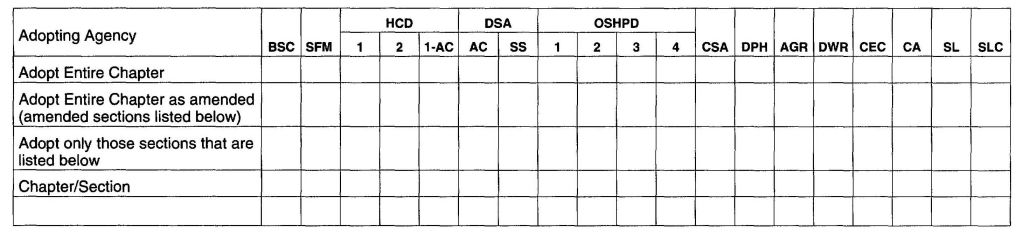
(This appendix is informative and is not part of the code. This appendix is an excerpt from the 2009 International Fuel Gas Code, coordinated with the section numbering of the International Residential Code.)
The provisions contained in this appendix are not mandatory unless specifically referenced in the adopting ordinance.
A.1 General piping considerations. The first goal of determining the pipe sizing for a fuel gas piping system is to make sure that there is sufficient gas pressure at the inlet to each appliance. The majority of systems are residential and the appliances will all have the same, or nearly the same, requirement for minimum gas pressure at the appliance inlet. This pressure will be about 5-inch water column (w.c.) (1.25 kPa), which is enough for proper operation of the appliance regulator to deliver about 3.5-inches water column (w.c.) (875 kPa) to the burner itself. The pressure drop in the piping is subtracted from the source delivery pressure to verify that the minimum is available at the appliance.
There are other systems, however, where the required inlet pressure to the different appliances, may be quite varied. In such cases, the greatest inlet pressure required must be satisfied, as well as the farthest appliance, which is almost always the critical appliance in small systems.
There is an additional requirement to be observed besides the capacity of the system at 100-percent flow. That requirement is that at minimum flow, the pressure at the inlet to any appliance does not exceed the pressure rating of the appliance regulator. This would seldom be of concern in small system if the source pressure is ½ psi (14-inch w.c.) (3.5 kPa) or less but it should be verified for systems with greater gas pressure at the point of supply.
To determine the size of piping used in a gas piping system, the following factors must be considered:
For any gas piping system, or special appliance,, or for conditions other than those covered by the tables provided in this code, such as longer runs, greater gas demands or greater pressure drops, the size of each gas piping system should be determined by standard engineering practices acceptable to the code official.
A.2 Description of tables
A.2.1 General. The quantity of gas to be provided at each outlet should be determined, whenever possible, directly from the manufacturer’s gas input Btu/h rating of the appliance that will be installed. In case the ratings of the appliances to be installed are not known, Table G2413.2 shows the approximate consumption (in Btu per hour) of certain types of typical household appliances.
To obtain the cubic feet per hour of gas required, divide the total Btu/h input of all appliances by the average Btu heating value per cubic foot of the gas. The average Btu per cubic foot of the gas in the area of the installation can be obtained from the serving gas supplier.
A.2.2 Low pressure natural gas tables. Capacities for gas at low pressure [less than 2.0 psig (13.8 KPa gauge)] in cubic feet per hour of 0.60 specific gravity gas for different sizes and lengths are shown in Table G2413.4(1) for iron pipe or equivalent rigid pipe in Table G2413.4(3) for smooth wall semi-rigid tubing, in Table G2413.4(5) for corrugated stainless steel tubing and in Table G2413.4(7) for polyethylene plastic pipe Tables G2413.4(1), G2413.4(3), G2413.4(5) and G2413.4(7) are based upon a pressure drop of 0.5-inch w.c. (125 Pa). In using these tables, an allowance (in equivalent length of pipe should be considered for any piping run with four or more fittings [see Table A.2.2].
A.2.3 Undiluted liquefied petroleum tables. Capacities in thousands of Btu per hour of undiluted liquefied petroleum gases based on a pressure drop of 0.5-inch w.c. (125 Pa) for different sizes and lengths are shown in the International Fuel Gas Code. See Appendix A of the code.
A.2.4 Natural gas specific gravity. Gas piping systems that are to be supplied with gas of a specific gravity of 0.70 or less can be sized directly from the tables provided in this code, unless the code official specifies that a gravity factor be applied. Where the specific gravity of the gas is greater than 0.70, the gravity factor should be applied.
Application of the gravity factor converts the figures given in the tables provided in this code to capacities for another gas of different specific gravity of the gas is greater than 0.70, the gravity factor should be applied. Such application is accomplished by multiplying the capacities given in the tables by the multipliers shown in Table A.2.4. In case the exact specific gravity does not appear in the table, choose the next higher value specific gravity shown.
| MITER ELBOWS3 (No. of miters) | WELDING TEES | VALVES (screwed, flanged, or welded) | ||||||||||
|---|---|---|---|---|---|---|---|---|---|---|---|---|
| 1-45° | 1-60° | 1-90° | 2-90°5 | 3-90°5 | Forged | Miter3 | Gate | Globe | Angle | Swing Check | ||
| For SI: 1 foot = 305 mm, 1 degree = 0.01745 rad. | ||||||||||||
| Note: Values for welded fittings are for conditions where bore is not obstructed by weld spatter or backing rings. If appreciably obstructed, use values for “Screwed Fittings.” | ||||||||||||
| 1. Flanged fittings have three-fourths the resistance of screwed elbows and tees. | ||||||||||||
| 2. Tabular figures give the extra resistance due to curvature alone to which should be added the full length of travel. | ||||||||||||
| 3. Small size socket-welding fittings are equivalent to miter elbows and meter tees. | ||||||||||||
| 4. Equivalent resistance in number of diameters of straight pipe computed for a value of (f-0.0075) from the relation(n-k/4f). | ||||||||||||
| 5. For condition of minimum resistance where the centerline length of each miter is between d and 2½d. | ||||||||||||
| 6. For pipe having other inside diameters, the equivalent resistance may be computer from the above n valves. | ||||||||||||
| Source: Crocker, S. Piping Handbook, 4th ed., Table XIV, pp .100-101. Copyright 1945 by McGraw-Hill, Inc. Used by permission of McGraw-Hill Book Company. | ||||||||||||
| k factor = | 0.45 | 0.90 | 1.80 | 0.60 | 0.45 | 1.35 | 1.80 | 0.21 | 10 | 5.0 | 2.5 | |
| L/d' ratio4 n = | 15 | 30 | 60 | 20 | 15 | 45 | 60 | 7 | 333 | 167 | 83 | |
| Nominal pipe size, inches | inside diameter d, inches, Schedule 406 | L = Equivalent Length in Feet of Schedule 40 (Standard-Weight) Straight Pipe6 | ||||||||||
| ½ | 0.622 | 0.78 | 1.55 | 3.10 | 1.04 | 0.78 | 2.33 | 3.10 | 0.36 | 17.3 | 8.65 | 4.32 |
| ¾ | 0.824 | 1.03 | 2.06 | 4.12 | 1.37 | 1.03 | 3.09 | 4.12 | 0.48 | 22.9 | 11.4 | 5.72 |
| 1 | 1.049 | 1.31 | 2.62 | 5.24 | 1.75 | 1.31 | 3.93 | 5.24 | 0.61 | 29.1 | 14.6 | 7.27 |
| 1¼ | 1.380 | 1.72 | 3.45 | 6.90 | 2.30 | 1.72 | 5.17 | 6.90 | 0.81 | 38.3 | 19.1 | 9.58 |
| 11⁄2 | 1.610 | 2.01 | 4.02 | 8.04 | 2.68 | 2.01 | 6.04 | 8.04 | 0.94 | 44.7 | 22.4 | 11.2 |
| 2 | 2.067 | 2.58 | 5.17 | 10.3 | 3.45 | 2.58 | 7.75 | 10.3 | 1.21 | 57.4 | 28.7 | 14.4 |
| 2½ | 2.469 | 3.08 | 6.16 | 12.3 | 4.11 | 3.08 | 9.25 | 12.3 | 1.44 | 68.5 | 34.3 | 17.1 |
| 3 | 3.068 | 3.84 | 7.67 | 15.3 | 5.11 | 3.84 | 11.5 | 15.3 | 1.79 | 85.2 | 42.6 | 21.3 |
| 4 | 4.026 | 5.04 | 10.1 | 20.2 | 6.71 | 5.04 | 15.1 | 20.2 | 2.35 | 112.0 | 56.0 | 28.0 |
| 5 | 5.047 | 6.30 | 12.6 | 25.2 | 8.40 | 6.30 | 18.9 | 25.2 | 2.94 | 140.0 | 70.0 | 35.0 |
| 6 | 6.065 | 7.58 | 15.2 | 30.4 | 10.1 | 7.58 | 22.8 | 30.4 | 3.54 | 168.0 | 84.1 | 42.1 |
| 8 | 7.981 | 9.97 | 20.0 | 40.0 | 13.3 | 9.97 | 29.9 | 40.0 | 4.65 | 222.0 | 111.0 | 55.5 |
| 10 | 10.02 | 12.5 | 25.0 | 50.0 | 16.7 | 12.5 | 37.6 | 50.0 | 5.85 | 278.0 | 139.0 | 69.5 |
| 12 | 11.94 | 14.9 | 29.8 | 59.6 | 19.9 | 14.9 | 44.8 | 59.6 | 6.96 | 332.0 | 166.0 | 83.0 |
| 14 | 13.13 | 16.4 | 32.8 | 65.6 | 21.9 | 16.4 | 49.2 | 65.6 | 7.65 | 364.0 | 182.0 | 91.0 |
| 16 | 15.00 | 18.8 | 37.5 | 75.0 | 25.0 | 18.8 | 56.2 | 75.0 | 8.75 | 417.0 | 208.0 | 104.0 |
| 18 | 16.88 | 21.1 | 42.1 | 84.2 | 28.1 | 21.1 | 63.2 | 84.2 | 9.85 | 469.0 | 234.0 | 117.0 |
| 20 | 18.81 | 23.5 | 47.0 | 94.0 | 31.4 | 23.5 | 70.6 | 94.0 | 11.0 | 522.0 | 261.0 | 131.0 |
| 24 | 22.63 | 28.3 | 56.6 | 113.0 | 37.8 | 28.3 | 85.0 | 113.0 | 13.2 | 629.0 | 314.0 | 157.0 |
| SPECIFIC GRAVITY | MULTIPLIER | SPECIFIC GRAVITY | MULTIPLIER |
|---|---|---|---|
| 0.35 | 1.31 | 1.00 | 0.78 |
| 0.40 | 1.23 | 1.10 | 0.74 |
| 0.45 | 1.16 | 1.20 | 0.71 |
| 0.50 | 1.10 | 1.30 | 0.68 |
| 0.55 | 1.04 | 1.40 | 0.66 |
| 0.60 | 1.00 | 1.50 | 0.63 |
| 0.65 | 0.96 | 1.60 | 0.61 |
| 0.70 | 0.93 | 1.70 | 0.59 |
| 0.75 | 0.90 | 1.80 | 0.58 |
| 0.80 | 0.87 | 1.90 | 0.56 |
| 0.85 | 0.84 | 2.00 | 0.55 |
| 0.90 | 0.82 | 2.10 | 0.54 |
A.2.5 Higher pressure natural gas tables. Capacities for gas at pressures of 2.0 psig (13.8 kPa) or greater in cubic feet per hour of 0.60 specific gravity gas for different sizes and lengths are shown in Table G2413.4(2) for iron pipe or equivalent rigid pipe, Table G2413.4 (4) for semi-rigid tubing, Table G2413.4(6) for corrugated stainless steel tubing and Table G2413.4(8) for polyethylene plastic pipe.
A.3 Use of capacity tables
A.3.1 Longest length method. This sizing method is conservative in its approach by applying the maximum operating conditions in the system as the norm for the system and by setting the length of pipe used to size any given part of the piping system to the maximum value.
To determine the size of each section of gas piping in a system within the range of the capacity tables, proceed as follows. (also see sample calculations included in this Appendix).
When a large number of piping components (such as elbows, tees and valves) are installed in a pipe run, additional pressure loss can be accounted for by the use of equivalent lengths. Pressure loss across any piping component can be equated to the pressure drop through a length of pipe. The equivalent length of a combination of only four elbows/tees can result in a jump to the next larger length row, resulting in a significant reduction in capacity. The equivalent lengths in feet shown in Table A.2.2 have been computed on a basis that the inside diameter corresponds to that of Schedule 40 (standard-weight) steel pipe, which is close enough for most purposes involving other schedules of pipe. Where a more specific solution for equivalent length is desired, this may be made by multiplying the actual inside diameter of the pipe in inches by n/12, or the actual inside diameter in feet by n (n can be read from the table heading). The equivalent length values can be used with reasonable accuracy for copper or brass fittings and bends although the resistance per foot of copper or brass pipe is less than that of steel. For copper or brass valves, however, the equivalent length of pipe should be taken as 45 percent longer than the values in the table, which are for steel pipe.
A.3.2 Branch length method. This sizing method reduces the amount of conservatism built into the traditional Longest Length Method. The longest length as measured from the meter to the furthest remote appliance is only used to size the initial parts of the overall piping system. The Branch Length Method is applied in the following manner:
A.3.3 Hybrid pressure method. The sizing of a 2 psi (13.8 kPa) gas piping system is performed using the traditional Longest Length Method but with modifications. The 2 psi (13.8 kPa) system consists of two independent pressure zones, and each zone is sized separately. The Hybrid Pressure Method is applied as follows.
The sizing of the 2 psi (13.8 kPa) section (from the meter to the line regulator) is as follows:
The low pressure section (all piping downstream of the line regulator) is sized as follows:
A.3.4 Pressure drop per 100 feet method. This sizing method is less conservative than the others, but it allows the designer to immediately see where the largest pressure drop occurs in the system. With this information, modifications can be made to bring the total drop to the critical appliance within the limitations that are presented to the designer.
559Follow the procedures described in the Longest Length Method for Steps (1) through (4) and (9).
For each piping segment, calculate the pressure drop based on pipe size, length as a percentage of 100 feet (30 480 mm), and gas flow. Table A.3.4 shows pressure drop per 100 feet (30 480mm) for pipe sizes from 1⁄2 inch (12.7 mm) through 2 inch (51 mm). The sum of pressure drops to the critical appliance is subtracted from the supply pressure to verify that sufficient pressure will be available. If not, the layout can be examined to find the high drop section(s) and sizing selections modified.
Note: Other values can be obtained by using the following equation:
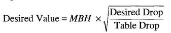
For example, if it is desired to get flow through ¾-inch (19.1 mm) pipe at 2 inches/100 feet, multiple the capacity of ¾-inch pipe at 1 inch/100 feet by the square root of the pressure ratio:

(MBH = 1000 Btu/h)
A.4 Use of sizing equations. Capacities of smooth wall pipe or tubing can also be determined by using the following formulae:
(1)High Pressure [1.5 psi (10.3 kPa) and above]:
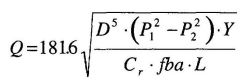
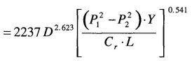
(2)Low Pressure [Less than 1.5 psi (10.3 kPa)]:
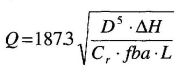
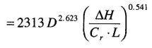
where:
Q = Rate, cubic feet per hour at 60°F and 30-inch mercury column
D = Inside diameter of pipe, in.
P1 = Upstream pressure, psia
P2 = Downstream pressure, psia
Y = Superexpansibility factor = 1/supercompressibility factor
Cr = Factor for viscosity, density and temperature*
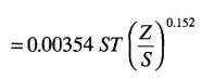
Note: See Table 402.4 for Y and C, for natural gas and propane.
S = Specific gravity of gas at 60°F and 30-inch mercury column (0.60) for natural gas, 1.50 for propane), or = 1488μ
T = Absolute temperature, °F or = t + 460
t = Temperature, °F
Z = Viscosity of gas, centipoise (0.012 for natural gas, 0.008 for propane), or = 1488μ
fba = Base friction factor for air at 60°F (CF=1)
L = Length of pipe, ft
ΔH = Pressure drop, in. w.c. (27.7 in. H2O = 1 psi)
(For SI, see Section G2413.4)
A.5 Pipe and tube diameters. Where the internal diameter is determined by the formulas in Section G2413.4, Tables A.5.1 and A.5.2 can be used to select the nominal or standard pipe size based on the calculated internal diameter.
| PRESSURE DROP PER 100 FEET IN INCHES W.C. | PIPE SIZES (inch) | |||||
|---|---|---|---|---|---|---|
| ½ | ¾ | 1 | 1¼ | 1½ | 2 | |
| For SI: 1 inch = 25.4 mm, 1 foot = 304.8 mm. | ||||||
| 0.2 | 31 | 64 | 121 | 248 | 372 | 716 |
| 0.3 | 38 | 79 | 148 | 304 | 455 | 877 |
| 0.5 | 50 | 104 | 195 | 400 | 600 | 1160 |
| 1.0 | 71 | 147 | 276 | 566 | 848 | 1640 |
| NOMINAL SIZE (in.) | INTERNAL DIAMETER (in.) | NOMINAL SIZE (in.) | INTERNAL DIAMETER (in.) |
|---|---|---|---|
| ¼ | 0.364 | 1½ | 1.610 |
| 3/8 | 0.493 | 2 | 2.067 |
| ½ | 0.622 | 2½ | 2.469 |
| ¾ | 0.824 | 3 | 3.068 |
| 1 | 1.049 | 3½ | 3.548 |
| 1¼ | 1.380 | 4 | 4.026 |
A.6 Use of sizing charts. A third method of sizing gas piping is detailed below as an option that is useful when large quantities of piping are involved in a job (e.g., an apartment house) and material costs are of concern. If the user is not completely familiar with this method, the resulting pipe sizing should be checked by a knowledgeable gas engineer. The sizing charts are applied as follows.
| TUBE TYPE | NOMINAL OR STANDARD SIZE (Inches) | INTERNAL DIAMETER (Inches) |
|---|---|---|
| K | ¼ | 0.305 |
| L | ¼ | 0.315 |
| ACR (D) | 3⁄8 | 0.315 |
| ACR (A) | 3⁄8 | 0.311 |
| K | 3⁄8 | 0.402 |
| L | 3⁄8 | 0.430 |
| ACR (D) | ½ | 0.430 |
| ACR (A) | ½ | 0.436 |
| K | ½ | 0.527 |
| L | ½ | 0.545 |
| ACR (D) | 5⁄8 | 0.545 |
| ACR (A) | 5⁄8 | 0.555 |
| K | 5⁄8 | 0.652 |
| L | 5⁄8 | 0.666 |
| ACR (D) | ¾ | 0.666 |
| ACR (A) | ¾ | 0.680 |
| K | ¾ | 0.745 |
| L | ¾ | 0.785 |
| ACR | 7⁄8 | 0.785 |
| K | 1 | 0.995 |
| L | 1 | 1.025 |
| ACR | 1 1/8 | 1.025 |
| K | 1¼ | 1.245 |
| L | 1¼ | 1.265 |
| ACR | 1 3⁄8 | 1.265 |
| K | 1½ | 1.481 |
| L | 1½ | 1.505 |
| ACR | 1 5⁄8 | 1.505 |
| K | 2 | 1.959 |
| L | 2 | 1.985 |
| ACR | 2 1⁄8 | 1.985 |
| K | 2½ | 2.435 |
| L | 2½ | 2.465 |
| ACR | 2 5/8 | 2.465 |
| K | 3 | 2.907 |
| L | 3 | 2.945 |
| ACR | 3 1⁄8 | 2.945 |
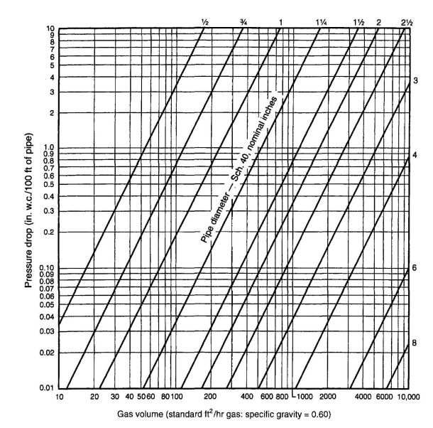
FIGURE A.6(a)
CAPACITY OF NATURAL GAS PIPING, LOW PRESSURE (0.60 WC)
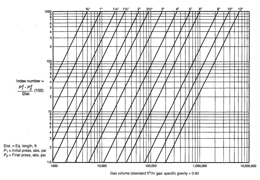
FIGURE A.6 (b)
CAPACITY OF NATURAL GAS PIPING, HIGH PRESSURE (1.5 psi and above)
A.7 Examples of piping system design and sizing
A.7.1 Example 1: Longest length method. Determine the required pipe size of each section and outlet of the piping system shown in Figure A.7.1, with a designated pressure drop of 0.5-inch w.c. (125 Pa) using the Longest Length Method. The gas to be used has 0.60 specific gravity and a heating value of 1,000 Btu⁄ft3 (37.5 MJ⁄m3).
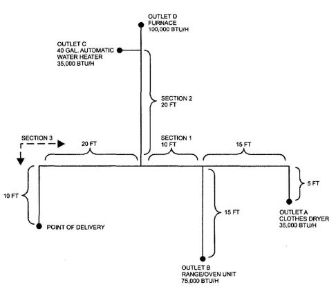
FIGURE A.7.1
PIPING PLAN SHOWING A STEEL PIPING SYSTEM
Solution:
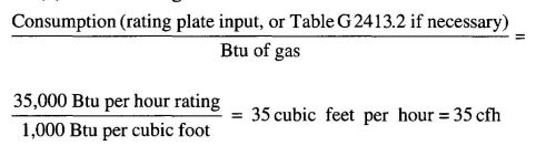
Section A.7.2 through A7.4 note: These examples are based on tables found in the International Fuel Gas Code.
A.7.2 Example 2: Hybrid or dual pressure system. Determine the required CSST size of each section of the piping system shown in Figure A.7.2, with a designated pressure drop of 1 psi (6.9 kPa) for the 2 psi (13.8 kPa) section and 3-inch w.c. (0.75 kPa)pressure drop for the 13-inch w.c. (2.49 kPa) section. The gas to be used has 0.60 specific gravity and a heating value of 1,000 Btu⁄ft3 (37.5 MJ⁄m3).
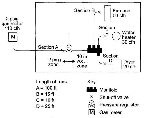
FIGURE A.7.2
PIPING PLAN SHOWING A CSST SYSTEM
Solution
Note: It is not unusual to oversize the supply line by 25 to 50 percent of the as-installed load. EHD size 18 has a capacity of 189 cfh (5.35 m3⁄hr).
A.7.3 Example 3: Branch length method. Determine the required semi-rigid copper tubing size of each section of the piping system shown in Figure A.7.3, with a designated pressure drop of 1-inch w.c. (250 Pa) (using the Branch Length Method). The gas to be used has 0.60 specific gravity and a heating value of 1,000Btu⁄ft3 (37.5 MJ⁄m3).
Solution
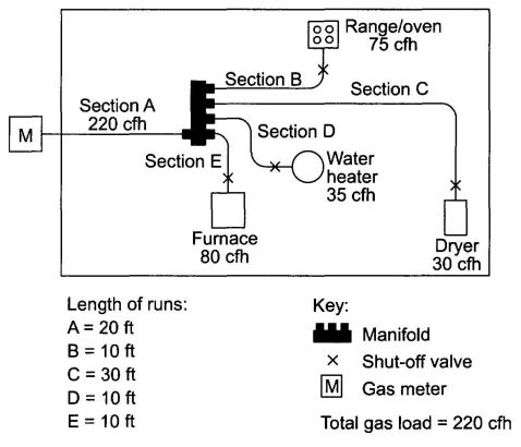
A.7.4 Example 4: Modification to existing piping system. Determine the required CSST size for Section G (retrofit application) of the piping system shown in Figure A.7.4, with a designated pressure drop of 0.5-inch w.c. (125 Pa) using the branch length method. The gas to be used has 0.60 specific gravity and a heating value of 1,000 Btu⁄ft3 (37.5 MJ⁄m3).
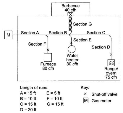
FIGURE A.7.4
PIPING PLAN SHOWING A MODIFICATION TO EXISTING PIPING SYSTEM
Solution
A.7.5 Example 5: Calculating pressure drops due to temperature changes. A test piping system is installed on a warm autumn afternoon when the temperature is 70°F (21°C). In accordance with local custom, the new piping system is subjected to an air pressure test at 20 psig (138 kPa). Overnight, the temperature drops and when the inspector shows up first thing in the morning the temperature is 40°F (4°C).
If the volume of the piping system is unchanged, then the formula based on Boyle' and Charles' law for determining the new pressure at a reduced temperature is as follows:

where:
T1 = Initial temperature, absolute (T1 + 459)
T2 = Final temperature, absolute (T2 + 459)
P1 = Initial pressure, psia (P1 + 14.7)
P2 = Final pressure, psia (P2 + 14.7)
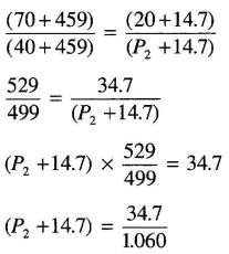
P2 = 32.7 – 14.7
P2 = 18 psig
Therefore, the gauge could be expected to register 18 psig (124 kPa) when the ambient temperature is 40°F (4°C).
A7.6 Example 6: Pressure drop per 100 feet of pipe method.
Using the layout shown in Figure A.7.1 and ΔH = pressure drop, in w.c. (27.7 in. H2O = 1 psi), proceed as follows:
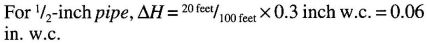

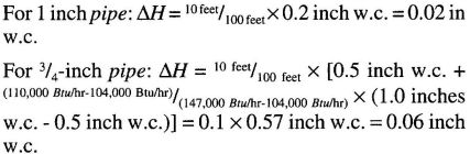
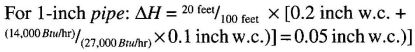 565
565 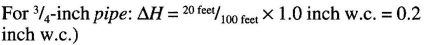
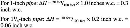
Note that interpolation for these options is ignored since the table values are close to the 245,000 Btu⁄hr carried by that section.
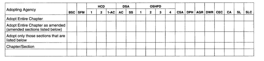
CALIFORNIA RESIDENTIAL CODE – MATRIX ADOPTION TABLE
APPENDIX B – SIZING OF VENTING SYSTEMS SERVING APPLIANCES EQUIPPED WITH DRAFT HOODS, CATEGORY I APPLIANCES, AND APPLIANCES LISTED FOR USE WITH TYPE B VENTS
(This appendix is informative and is not part of the code. This appendix is an excerpt from the 2009 International Fuel Gas Code, coordinated with the section numbering of the International Residential Code.)
The provisions contained in this appendix are not mandatory unless specifically referenced in the adopting ordinance.
Example 1: Single draft-hood-equipped appliance.
An installer has a 120,000 British thermal unit (Btu) per hour input appliance with a 5-inch-diameter draft hood outlet that needs to be vented into 10-foot-high Type B vent system. What size vent should be used assuming(a) a 5-foot lateral single-wall metal vent connector is used with two 90-degree elbows, or (b) a 5-foot lateral single-wall metal vent connector is used with three 90-degree elbows in the vent system?
Solution:
Table G2428.2(2) should be used to solve this problem, because single-wall metal vent connectors are being used with a Type B vent.
122,000 (0.90) = 110,000 for 5-inch vent From Table G2428.2.(2), Select 6-inch vent 186,000 (0.90) = 167,000; This is greater than the required 120,000. Therefore, use a 6-inch vent and connector where three elbows are used.
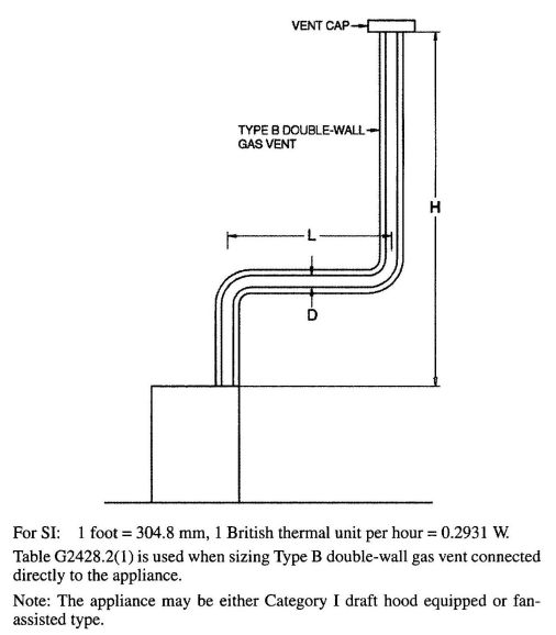
FIGURE B-1
TYPE B DOUBLE-WALL VENT SYSTEM SERVING A SINGLE APPLIANCE WITH A TYPE B DOUBLE-WALL VENT
FIGURE B-2
TYPE B DOUBLE-WALL VENT SYSTEM SERVING A SINGLE APPLIANCE WITH A SINGLE-WALL METAL VENT CONNECTOR
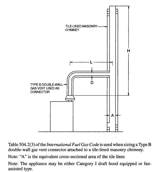
FIGURE B-3
VENT SYSTEM SERVING A SINGLE APPLIANCE WITH A MASONRY CHIMNEY OF TYPE B DOUBLE-WALL VENT CONNECTOR
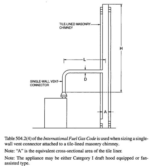
FIGURE B-4
VENT SYSTEM SERVING A SINGLE APPLIANCE USING A MASONRY CHIMNEY AND A SINGLE-WALL METAL VENT CONNECTOR
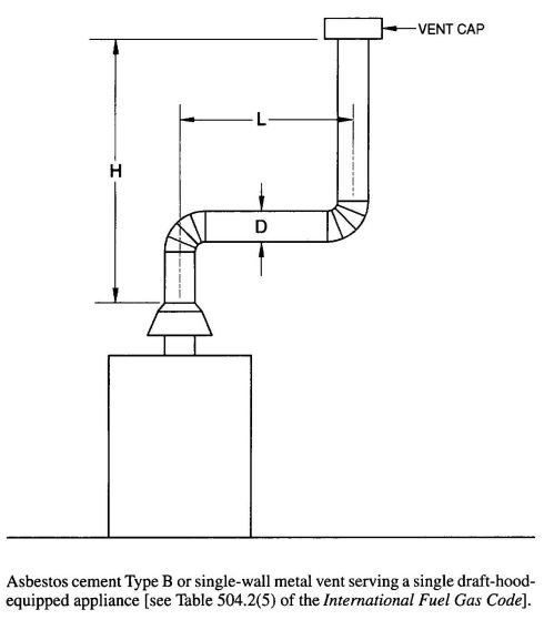
FIGURE B-5
ASBESTOS CEMENT TYPE B OR SINGLE-WALL METAL VENT SYSTEM SERVING A SINGLE DRAFT-HOOD-EQUIPPED APPLIANCE
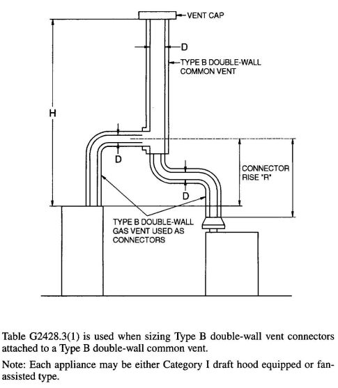
FIGURE B-6
VENT SYSTEM SERVING TWO OR MORE APPLIANCES WITH TYPE B DOUBLE-WALL VENT AND TYPE B DOUBLE-WALL VENT CONNECTOR
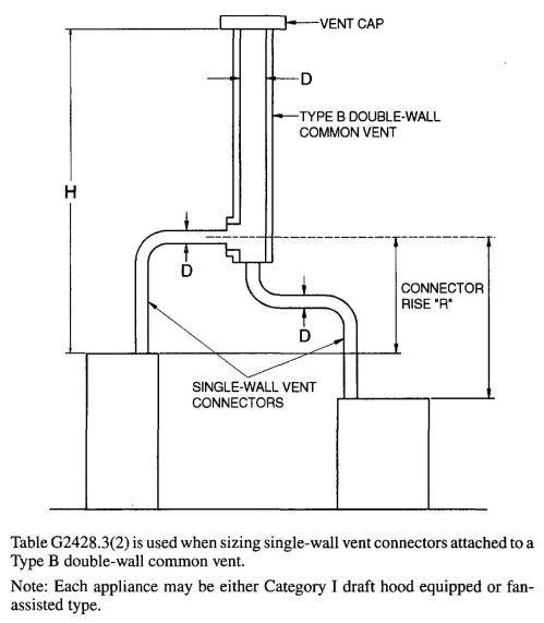
FIGURE B-7
VENT SYSTEM SERVING TWO OR MORE APPLIANCES WITH TYPE B DOUBLE-WALL VENT AND SINGLE-WALL METAL VENT CONNECTORS
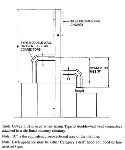
FIGURE B-8
MASONRY CHIMNEY SERVING TWO OR MORE APPLIANCES WITH TYPE B DOUBLE-WALL VENT CONNECTOR
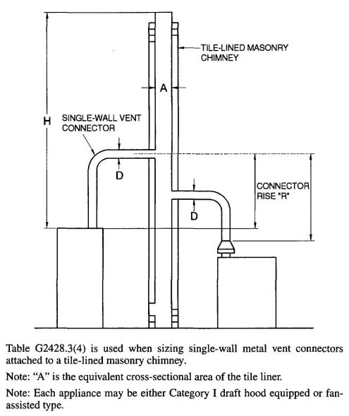
FIGURE B-9
MASONRY CHIMNEY SERVING TWO OR MORE APPLIANCES WITH SINGLE-WALL METAL VENT CONNECTORS
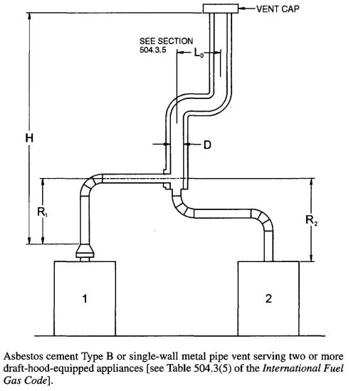
FIGURE B-10
ASBESTOS CEMENT TYPE B OR SINGLE-WALL METAL VENT SYSTEM SERVING TWO OR MORE DRAFT-HOOD-EQUIPPED APPLIANCES
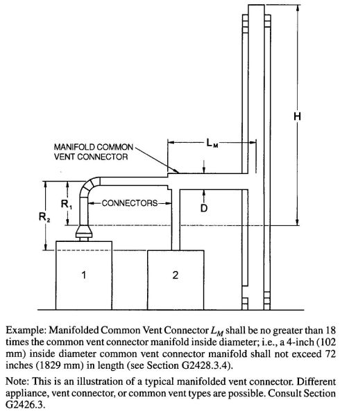
FIGURE B-11
USE OF MANIFOLD COMMON VENT CONNECTOR
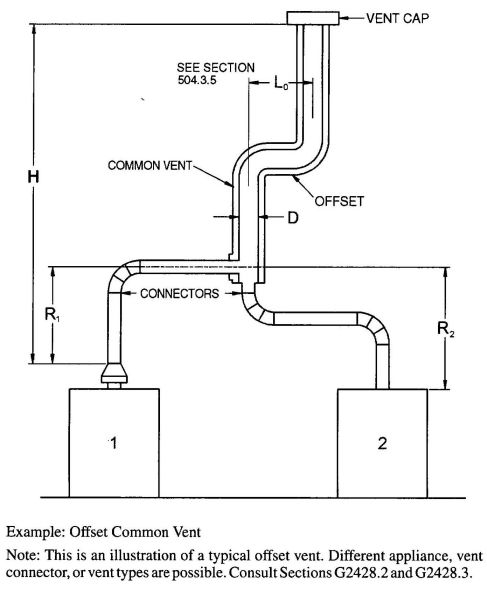
FIGURE B-12
USE OF OFFSET COMMON VENT
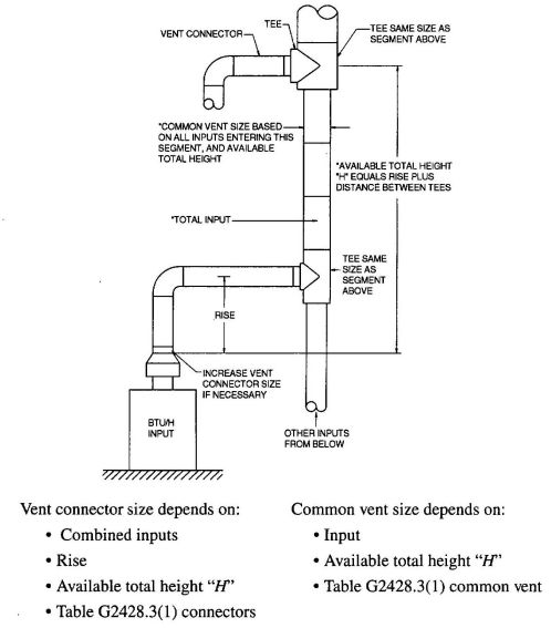
FIGURE B-13
MULTISTORY GAS VENT DESIGN PROCEDURE FOR EACH SEGMENT OF SYSTEM
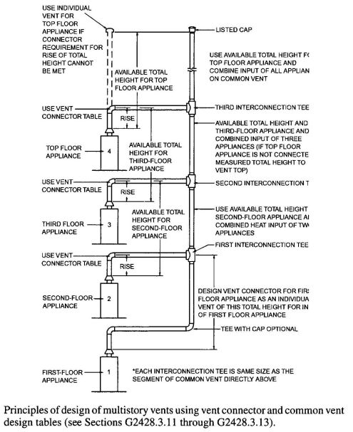
FIGURE B-14
MULTISTORY VENT SYSTEMS
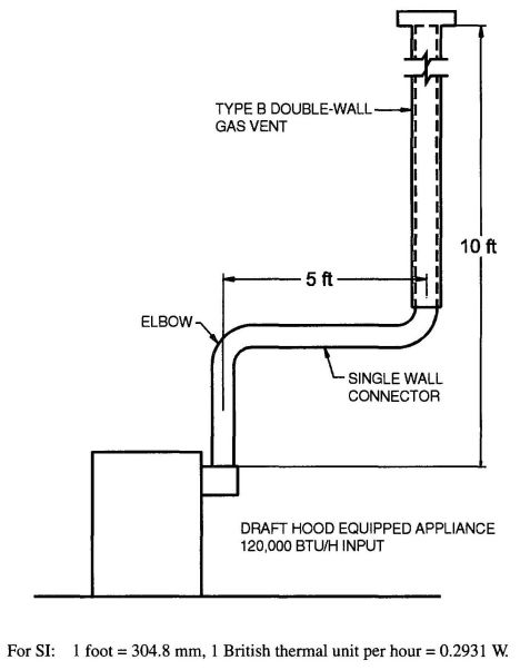
FIGURE B-15 (EXAMPLE 1)
SINGLE DRAFT-HOOD-EQUIPPED APPLIANCE
Example 2: Single fan-assisted appliance.
An installer has an 80,000 Btu per hour input fan-assisted appliance that must be installed using 10 feet of lateral connector attached to a 30-foot-high Type B vent. Two 90-degree elbows are needed for the installation. Can a single-wall metal vent connector be used for this application?
Solution:
Table G2428.2(2) refers to the use of single-wall metal vent connectors with Type B vent. In the first column find the row associated with a 30-foot height and a 10-foot lateral. Read across this row, looking at the FAN Min and FAN Max columns, to find that a 3-inch-diameter single-wall metal vent connector is not recommended. Moving to the next larger size single wall connector (4 inches), note that a 4-inch-diameter single-wall metal connector has a recommended minimum vent capacity of 91,000 Btu per hour and a recommended maximum vent capacity of 144,000 Btu per hour. The 80,000 Btu per hour fan-assisted appliance is outside this range, so the conclusion is that a single-wall metal vent connector cannot be used to vent this appliance using 10 feet of lateral for the connector.
However, if the 80,000 Btu per hour input appliance could be moved to within 5 feet of the vertical vent, then a 4-inch single-wall metal connector could be used to vent the appliance. Table G2428.2(2) shows the acceptable range of vent capacities for a 4-inch vent with 5 feet of lateral to be between 72,000 Btu per hour and 157,000 Btu per hour.
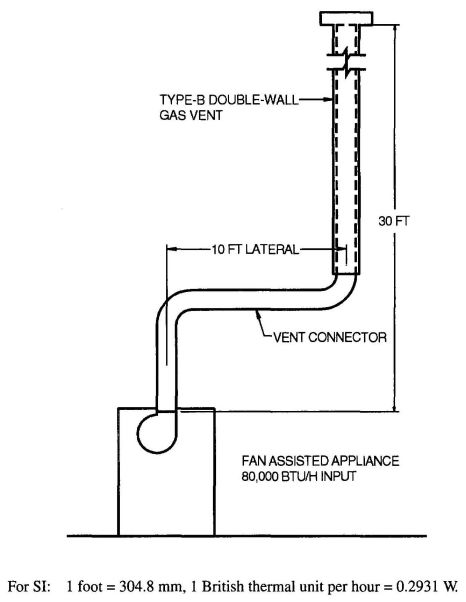
FIGURE B-16 (EXAMPLE 2)
SINGLE FAN-ASSISTED APPLIANCE
If the appliance cannot be moved closer to the vertical vent, then Type B vent could be used as the connector material. In this case, Table G2428.2(1) shows that for a 30-foot-high vent with 10 feet of lateral, the acceptable range of vent capacities for a 4-inch-diameter vent attached to a fan-assisted appliance is between 37,000 Btu per hour and 150,000 Btu per hour.
Example 3: Interpolating between table values.
An installer has an 80,000 Btu per hour input appliance with a 4-inch-diameter draft hood outlet that needs to be vented into a 12-foot-high Type B vent. The vent connector has a 5-foot lateral length and is also Type B. Can this appliance be vented using a 4-inch-diameter vent?
Solution:
Table G2428.2(1) is used in the case of an all Type B vent system. However, since there is no entry in Table G2428.2(1) for a height of 12 feet, interpolation must be used. Read down the 4-inch diameter NAT Max column to the row associated with 10-foot height and 5-foot lateral to find the capacity value of 77,000 Btu per hour. Read further down to the 15-foot height, 5-foot lateral row to find the capacity value of 87,000 Btu per hour. The difference between the 15-foot height capacity value and the 10-foot height capacity value is 10,000 Btu per hour. The capacity for a vent system with a 12-foot height is equal to the capacity for a 10-foot height plus 2/5 of the difference between the 10-foot and 15-foot height values, or 77,000 + 2/5 (10,000) = 81,000 Btu per hour. Therefore, a 4-inch-diameter vent may be used in the installation.
573EXAMPLES USING COMMON VENTING TABLES
Example 4: Common venting two draft-hood-equipped appliances.
A 35,000 Btu per hour water heater is to be common vented with a 150,000 Btu per hour furnace using a common vent with a total height of 30 feet. The connector rise is 2 feet for the water heater with a horizontal length of 4 feet. The connector rise for the furnace is 3 feet with a horizontal length of 8 feet. Assume single-wall metal connectors will be used with Type B vent. What size connectors and combined vent should be used in this installation?
Solution:
Table G2428.3(2) should be used to size single-wall metal vent connectors attached to Type B vertical vents. In the vent connector capacity portion of Table G2428.3(2), find the row associated with a 30-foot vent height. For a 2-foot rise on the vent connector for the water heater, read the shaded columns for draft-hood-equipped appliances to find that a 3-inch-diameter vent connector has a capacity of 37,000 Btu per hour. Therefore, a 3-inch single-wall metal vent connector may be used with the water heater. For a draft-hood-equipped furnace with a 3-foot rise, read across the appropriate row to find that a 5-inch-diameter vent connector has a maximum capacity of 120,000 Btu per hour (which is too small for the furnace) and a 6-inch-diameter vent connector has a maximum vent capacity of 172,000 Btu per hour. Therefore, a 6-inch-diameter vent connector should be used with the 150,000 Btu per hour furnace. Since both vent connector horizontal lengths are less than the maximum lengths listed in Section G2428.3.2, the table values may be used without adjustments.
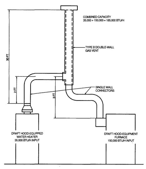
FIGURE B-17 (EXAMPLE 4)
COMMON VENTING TWO DRAFT-HOOD-EQUIPPED APPLIANCES
In the common vent capacity portion of Table G2428.3(2), find the row associated with a 30-foot vent height and read over to the NAT + NAT portion of the 6-inch-diameter column to find a maximum combined capacity of 257,000 Btu per hour. Since the two appliances total only 185,000 Btu per hour, a 6-inch common vent may be used.
Example 5a: Common venting a draft-hood-equipped water heater with a fan-assisted furnace into a Type B vent.
In this case, a 35,000 Btu per hour input draft-hood-equipped water heater with a 4-inch-diameter draft hood outlet, 2 feet of connector rise, and 4 feet of horizontal length is to be common vented with a 100,000 Btu per hour fan-assisted furnace with a 4-inch-diameter flue collar, 3 feet of connector rise, and 6 feet of horizontal length. The common vent consists of a 30-foot height of Type B vent. What are the recommended vent diameters for each connector and the common vent? The installer would like to use a single-wall metal vent connector.
Solution:
Water Heater Vent Connector Diameter. Since the water heater vent connector horizontal length of 4 feet is less than the maximum value listed in Section G2428.3.2, the venting table values may be used without adjustments. Using the Vent Connector Capacity portion of Table G2428.3(2), read down the Total Vent Height (H) column to 30 feet and read across the 2-foot Connector Rise (R) row to the first Btu per hour rating in the NAT Max column that is equal to or greater than the water heater input rating. The table shows that a 3-inch vent connector has a maximum input rating of 37,000 Btu per hour. Although this is greater than the water heater input rating, a 3-inch vent connector is prohibited by Section G2428.3.17. A 4-
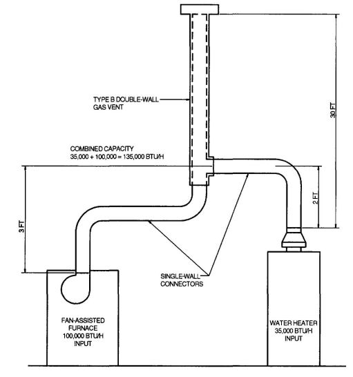
FIGURE B-18 (EXAMPLE 5A)
COMMON VENTING A DRAFT HOOD WITH A FAN-ASSISTED FURNACE INTO A TYPE B DOUBLE-WALL COMMON VENT
inch vent connector has a maximum input rating of 67,000 Btu per hour and is equal to the draft hood, outlet diameter. A 4-inch vent connector is selected. Since the water heater is equipped with a draft hood, there are no minimum input rating restrictions.
Furnace Vent Connector Diameter. Using the Vent Connector Capacity portion of Table G2428.3(2), read down the Total Vent Height (H) column to 30 feet and across the 3-foot Connector Rise (R) row. Since the furnace has a fan-assisted combustion system, find the first FAN Max column with a Btu per hour rating greater than the furnace input rating. The 4-inch vent connector has a maximum input rating of 119,000 Btu per hour and a minimum input rating of 85,000 Btu per hour. The 100,000 Btu per hour furnace in this example falls within this range, so a 4-inch connector is adequate. Since the furnace vent connector horizontal length of 6 feet does not exceed the maximum value listed in Section G2428.3.2, the venting table values may be used without adjustment. If the furnace had an input rating of 80,000 Btu per hour, then a Type B vent connector [see Table G2428.3(1)] would be needed in order to meet the minimum capacity limit.
Common Vent Diameter. The total input to the common vent is 135,000 Btu per hour. Using the Common Vent Capacity portion of Table G2428.3(2), read down the Total Vent Height (H) column to 30 feet and across this row to find the smallest vent diameter in the FAN + NAT column that has a Btu per hour rating equal to or greater than 135,000 Btu per hour. The 4-inch common vent has a capacity of 132,000 Btu per hour and the 5-inch common vent has a capacity of 202,000 Btu per hour. Therefore, the 5-inch common vent should be used in this example.
Summary. In this example, the installer may use a 4-inch-diameter, single-wall metal vent connector for the water heater and a 4-inch-diameter, single-wall metal vent connector for the furnace. The common vent should be a 5-inch-diameter Type B vent.
Example 5b: Common venting into a masonry chimney.
In this case, the water heater and fan-assisted furnace of Example 5a are to be common vented into a clay tile-lined masonry chimney with a 30-foot height. The chimney is not exposed to the outdoors below the roof line. The internal dimensions of the clay tile lineer are nominally 8 inches by 12 inches. Assuming the same vent connector heights, laterals, and materials found in Example 5a, what are the recommended vent connector diameters, and is this an acceptable installation?
Solution:
Table G2428.3(4) is used to size common venting installations involving single-wall connectors into masonry chimneys.
Water Heater Vent Connector Diameter. Using Table G2428.3(4), Vent Connector Capacity, read down the Total Vent Height (H) column to 30 feet, and read across the 2-foot Connector Rise (R) row to the first Btu per hour rating in the NAT Max column that is equal to or greater than the water heater input rating. The table shows that a 3-inch vent connector has a maximum input of only 31,000 Btu per hour while a 4-inch vent connector has a maximum input of 57,000 Btu per hour. A 4-inch vent connector must therefore be used.
Furnace Vent Connector Diameter. Using the Vent Connector Capacity portion of Table G2428.3(4), read down the Total Vent Height (H) column to 30 feet and across the 3-foot Connector Rise (R) row. Since the furnace has a fan-assisted combustion system, find the first FAN Max column with a Btu per hour rating greater than the furnace input rating. The 4-inch vent connector has a maximum input rating of 127,000 Btu per hour and a minimum input rating of 95,000 Btu per hour. The 100,000 Btu per hour furnace in this example falls within this range, so a 4-inch connector is adequate.
Masonry Chimney. From Table B-1, the equivalent area for a nominal liner size of 8 inches by 12 inches is 63.6 square inches. Using Table G2428.3(4), Common Vent Capacity, read down the FAN + NAT column under the Minimum Internal Area of Chimney value of 63 to the row for 30-foot height to find a capacity value of 739,000 Btu per hour. The combined input rating of the furnace and water heater, 135,000 Btu per hour, is less than the table value, so this is an acceptable installation.
Section G2428.3.13 requires the common vent area to be no greater than seven times the smallest listed appliance categorized vent area, flue collar area, or draft hood outlet area. Both appliances in this installation have 4-inch-diameter outlets. From Table B-1, the equivalent area for an inside diameter of 4 inches is 12.2 square inches. Seven times 12.2 equals 85.4, which is greater than 63.6, so this configuration is acceptable.
Example 5c: Common venting into an exterior masonry chimney.
In this case, the water heater and fan-assisted furnace of Examples 5a and 5b are to be common vented into an exterior masonry chimney. The chimney height, clay tile liner dimensions, and vent connector heights and laterals are the same as in Example 5b. This system is being installed in Charlotte, North Carolina. Does this exterior masonry chimney need to be relined? If so, what corrugated metallic liner size is recommended? What vent connector diameters are recommended?
Solution:
According to Section 504.3.20 of the International Fuel Gas Code, Type B vent connectors are required to be used with exterior masonry chimneys. Use Table 504.3(7) of the International Fuel Gas Code to size FAN+NAT common venting installations involving Type-B double wall connectors into exterior masonry chimneys.
The local 99-percent winter design temperature needed to use Table 504.3(7) can be found in the ASHRAE Handbook of Fundamentals. For Charlotte, North Carolina, this design temperature is 19°F.
Chimney Liner Requirement. As in Example 5b, use the 63 square inch Internal Area columns for this size clay tile liner. Read down the 63 square inch column of Table 504.3(7a) of the International Fuel Gas Code to the 30-foot height row to find that the combined appliance maximum input is 747,000 Btu per hour. The combined input rating of the appliances in this installation, 135,000 Btu per hour, is less than the maximum value, so this criterion is satisfied. Table 504.3(7b), at a 19°F design temperature, and at the same vent height and internal area used above, shows that the minimum allowable input rating of a
575space-heating appliance is 470,000 Btu per hour. The furnace input rating of 100,000 Btu per hour is less than this minimum value. So this criterion is not satisfied, and an alternative venting design needs to be used, such as a Type B vent shown in Example 5a or a listed chimney liner system shown in the remainder of the example.
According to Section G2428.3.15, Table G2428.3(1) or G2428.3(2) is used for sizing corrugated metallic liners in masonry chimneys, with the maximum common vent capacities reduced by 20 percent. This example will be continued assuming Type B vent connectors.
Water Heater Vent Connector Diameter. Using Table G2428.3(1), Vent Connector Capacity, read down the Total Vent Height (H) column to 30 feet, and read across the 2-foot Connector Rise (R) row to the first Btu/h rating in the NAT Max column that is equal to or greater than the water heater input rating. The table shows that a 3-inch vent connector has a maximum capacity of 39,000Btu/h. Although this rating is greater than the water heater input rating, a 3inch Vent Connector is prohibited by Section G2428.3.17. A 4-inch vent connector has a maximum input rating of 70,000 Btu/h and is equal to the draft hood outlet diameter. A 4-inch vent connector is selected.
Furnace Vent Connector Diameter. Using Table G2428.3(1), Vent Connector Capacity, read down the Vent Height (H) column to 30 feet, and read across the 3-foot Connector Rise (R) row to the firstBtu per hour rating in the FAN Max column that is equal to or greater than the furnace in this example falls within this range, so a 4-inch connector is adequate.
Chimney Liner Diameter. The total input to the common vent is 135,000 Btu per hour. Using the Common Vent Capacity Portion of Table G2428.3(1), read down the Vent Height (H) column to 30 feet and across this row to find the smallest vent diameter in the FAN+NAT column that has a Btu per hour rating greater than 135,000Btu per hour. The 4-inch common vent has a capacity of 138,000Btu per hour. Reducing the maximum capacity by 20 percent (Section G2428.3.15) results in a maximum capacity for a 4-inch corrugated liner of 110,000 Btu per hour, less than the total input of 135,000 Btu per hour. So a larger liner is needed. The 5-inch common vent capacity listed in Table G2428.3(1) is 210,000 Btu per hour, and after reducing by 20 percent is 168,000Btu per hour. Therefore, a 5-inch corrugated metal liner should be used in this example.
Single-Wall Connectors. Once it has been established that relining the chimney is necessary, Type B double-wall vent connectors are not specifically required. This example could be redone using Table G2428.3(2) for single-wall vent connectors. For this case, the vent connector and liner diameters would be the same as found above with Type B double-wall connectors.
| NOMINAL LINER SIZE (inches) | INSIDE DIMENSIONS OF LINER (inches) | INSIDE DIAMETER OR EQUIVALENT DIAMETER (inches) | EQUIVALENT AREA (square inches) |
|---|---|---|---|
| For SI: 1 inch = 25.4 mm, 1 square inch= 645.16 mm2 | |||
| a. Where liner sizes differ dimensionally from those shown in Table B-1, equivalent diameters may be determined from published tables for square and rectangular ducts of equivalent carrying capacity or by other engineering methods. | |||
| 4 × 8 | 2½ × 6½ | 4 | 12.2 |
| 5 | 19.6 | ||
| 6 | 28.3 | ||
| 7 | 38.3 | ||
| 8 × 8 | 6¾ × 6¾ | 7.4 | 42.7 |
| 8 | 50.3 | ||
| 8 × 12 | 6½ × 10½ | 9 | 63.6 |
| 10 | 78.5 | ||
| 12 × 12 | 9¾ × 9¾ | 10.4 | 83.3 |
| 11 | 95 | ||
| 12 × 16 | 9½ × 13½ | 11.8 | 107.5 |
| 12 | 113.0 | ||
| 14 | 153.9 | ||
| 16 × 16 | 13¼ × 13¼ | 14.5 | 162.9 |
| 15 | 176.7 | ||
| 16 × 20 | 13 × 17 | 16.2 | 206.1 |
| 18 | 254.4 | ||
| 20 × 20 | 16¾ × 16¾ | 18.2 | 260.2 |
| 20 | 314.1 | ||
| 20 × 24 | 16½ × 20½ | 20.1 | 314.1 |
| 22 | 380.1 | ||
| 24 × 24 | 20¼ × 20¼ | 22.1 | 380.1 |
| 24 | 452.3 | ||
| 24 × 28 | 20¼×20¼ | 24.1 | 456.2 |
| 28 × 28 | 24¼ × 24¼ | 26.4 | 543.3 |
| 27 | 572.5 | ||
| 30 × 30 | 25½ × 25½ | 27.9 | 607 |
| 30 | 706.8 | ||
| 30 × 36 | 25½ × 31½ | 30.9 | 749.9 |
| 33 | 855.3 | ||
| 36 × 36 | 31½ × 31½ | 34.4 | 929.4 |
| 36 | 1017.9 | ||
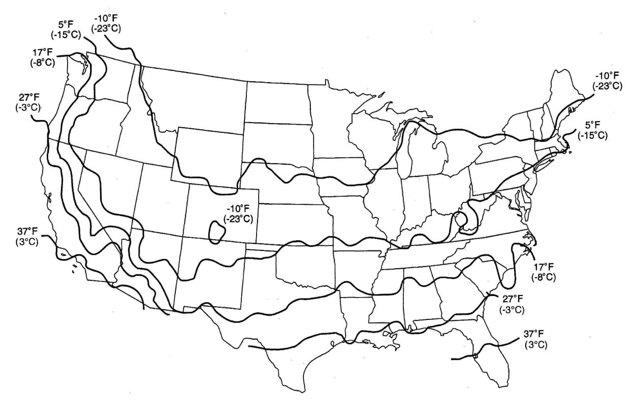
FIGURE B-19
577 578CALIFORNIA RESIDENTIAL CODE - MATRIX ADOPTION TABLE APPENDIX C - EXIT TERMINALS OF MECHANICAL DRAFT AND DIRECT-VENT VENTING SYSTEMS
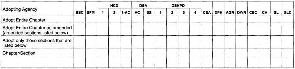
(This appendix is informative and is not part of the code. This appendix is an excerpt from the 2009 International Fuel Gas Code, coordinated with the section numbering of the International Residential Code.)
The provisions contained in this appendix are not mandatory unless specifically referenced in the adopting ordinance.
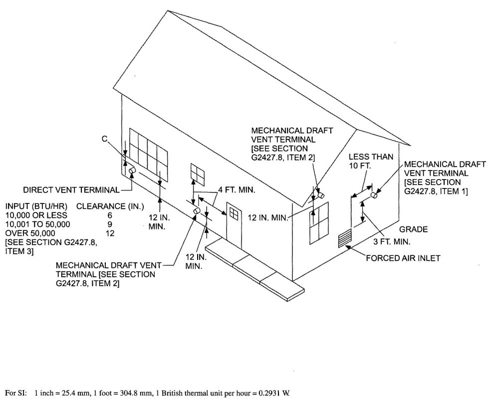
FIGURE C-1
EXIT TERMINALS OF MECHANICAL DRAFT AND DIRECT-VENT VENTING SYSTEMS
CALIFORNIA RESIDENTIAL CODE–MATRIX ADOPTION TABLE
APPENDIX D–RECOMMENDED PROCEDURE FOR SAFETY INSPECTION OF AN EXISTING APPLIANCE INSTALLATION
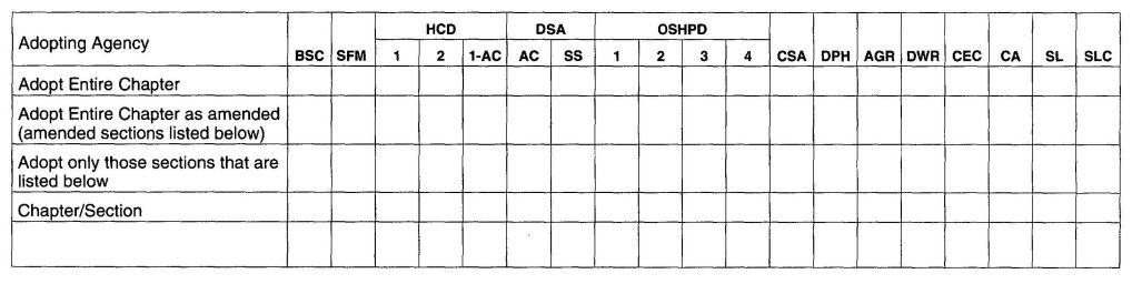
(This appendix is informative and is not part of the Code. This appendix is an excerpt from the 2009 International Fuel Gas Code, coordinated with the section numbering of the International Residential Code.)
The provisions contained in this appendix are not mandatory unless specifically referenced in the adopting ordinance.
The following procedure is intended as a guide to aid in determining that an appliance is properly installed and is in a safe condition for continuing use.
This procedure is intended for central furnace and boiler installation and may not be applicable to all installations.
The following steps should be followed in making the safety inspection:
If the appliance is equipped with high and low flame controlling or flame modulation, check for proper main burner operation at low flame.
CALIFORNIA RESIDENTIAL CODE – MATRIX ADOPTION TABLE
APPENDIX E – MANUFACTURED HOUSING USED AS DWELLINGS
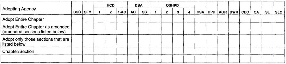
(Note: This appendix is not adopted. See California Code of Regulations, Title 25.)
AE101.1 General. These provisions shall be applicable only to a manufactured home used as a single dwelling unit installed on privately owned (nonrental) lots and shall apply to the following:
These provisions shall not be applicable to the design and construction of manufactured homes and shall not be deemed to authorize either modifications or additions to manufactured homes where otherwise prohibited.
Exception: In addition to these provisions, new and replacement manufactured homes to be located in flood hazard areas as established in Table R301.2(1) of the International Residential Code shall meet the applicable requirements of Section R322 of the International Residential Code.
AE102.1 General. Manufactured homes and their building service equipment to which additions, alterations or repairs are made shall comply with all the requirements of these provisions for new facilities, except as specifically provided in this sections.
AE102.2 Additions, alterations or repairs. Additions made to a manufactured homes shall conform to one of the following:
Additions shall be structurally separated from the manufactured home.
Exception: A structural separation need not be provided when structural calculations are provided to justify the omission of such separation.
Alterations or repairs may be made to any manufactured home or to its building service equipment without requiring the existing manufactured home or its building service equipment to comply with all the requirements of these provisions, provided the alteration or repair conforms to that required for new construction, and provided further that no hazard to life, health or safety will be created by such additions, alterations or repairs.
Alterations or repairs to an existing manufactured home which are nonstructural and do not adversely affect any structural member or any part of the building or structure having required fire protection may be made with materials equivalent to those of which the manufactured home structure is constructed, subject to approval by the building official.
Exception: The installation or replacement of glass shall be required for new installations.
Minor additions, alterations and repairs to existing building service equipment installations may be made in accordance with the codes in effect at the time the original installation was made subject to approval of the building official, and provided such additions, alterations and repairs will not cause the existing building service equipment to become unsafe, insanitary or overloaded.
AE102.3 Existing installations. Building service equipment lawfully in existence at the time of the adoption of the applicable codes may have their use, maintenance or repair continued if the use, maintenance or repair is in accordance with the original design and no hazard to life, health or property has been created by such building service equipment.
AE102.4 Existing occupancy. Manufactured homes which are in existence at the time of the adoption of these provisions may have their existing use or occupancy continued if such use or occupancy was legal at the time of the adoption of these provisions, provided such continued use is not dangerous to life, health and safety.
The use or occupancy of any existing manufactured home shall not be changed unless evidence satisfactory to the building official is provided to show compliance with all applicable provisions of the codes adopted by this jurisdiction. Upon any change in use or occupancy, the Manufactured home shall cease to be classified as such within the intent of these provisions.
589AE102.5 Maintenance. All manufactured homes and their building service equipment, existing and new, and all parts thereof shall be maintained in a safe and sanitary condition. All device or safeguards which are required by applicable codes or by the Manufactured Home Standards shall be maintained in conformance with the code or standard under which it was installed. The owner or the owner’s designated agent shall be responsible for the maintenance of manufactured homes, accessory buildings, structures and their building service equipment. To determine compliance with this subsection, the building official may cause any manufactured home,accessory building or structure to be reinspected.
AE102.6 Relocation. Manufactured homes which are to be relocated within this jurisdiction shall comply with these provisions.
AE201.1 General. For the purpose of these provisions, certain abbreviations, terms, phrases, words and their derivatives shall be construed as defined or specified herein.
ACCESSORY BUILDING. Any building or structure, or portion thereto, located on the same property as a manufactured home which does not qualify as a manufactured home as defined herein.
BUILDING SERVICE EQUIPMENT. Refers to the plumbing, mechanical and electrical equipment including piping, wiring, fixtures and other accessories which provided sanitation, lighting, heating ventilation, cooling, fire protection and facilities essential for the habitable occupancy of a manufactured home or accessory building or structure for its designated use and occupancy.
MANUFACTURED HOME. A structure transportable in one or more sections which, in the traveling mode, is 8 body feet (2438 body mm) or more in width or 40 body feet (12 192 body mm) or more in length or, when erected on site, is 320 or more square feet (30 m2), and which is built on a permanent chassis and designed to be used as a dwelling with or without a permanent foundation when connected to the required utilities, and includes the plumbing, heating, air-conditioning and electrical systems contained therein; except that such term shall include any structure which meets all the requirements of this paragraph except the size requirements and with respect to which the manufactures voluntarily files a certification required by the secretary (HUD) and complies with the standards established under this title.
For mobile homes built prior to June 15, 1976, a label certifying compliance to the Standard for Mobile Homes, NFPA 501, ANSI 119.1, in effect at the time of manufacture is required. For the purpose of these provisions, a mobile home shall be considered a manufactured home.
MANUFACTURED HOME INSTALLATION. Construction which is required for the installation of amanufactured home, including the construction of the foundation system, required structural connections thereto and the installation of on-site water, gas, electrical and sewer systems and connections thereto which are necessary for the normal operation of the manufactured home.
MANUFACTURED HOME STANDARDS. The Manufactured Home Construction and Safety Standards as promulgated by the United States Department of Housing and Urban Development.
PRIVATELY OWNED (NONRENTAL) LOT. A parcel of real estate outside of a manufactured home rental community (park) where the land and the manufactured home to be installed thereon are held in common ownership.
AE301.1 Initial installation. A manufactured home shall not be installed on a foundation system, reinstalled or altered without first obtaining a permit from the building official. A separate permit shall be required for each manufactured home installation. When approved by the building official, such permit may include accessory buildings and structures and their building service equipment when the accessory buildings or structures will be constructed in conjunction with the manufactured home installation.
AE301.2 Additions, alterations and repairs to a manufactured home. A permit shall be obtained to alter, remodel, repair or add accessory buildings or structure to a manufactured home subsequent to its initial installation. Permit issuance and fees there for shall be in conformance with the codes applicable to the type of work involved.
An addition made to a manufactured home as defined in these provisions shall comply with these provisions.
AE301.3 Accessory buildings. Except as provided in Section AE301.1, permits shall be required for all accessory buildings and structures and their building service equipment. Permit insuance and fees there for shall be in conformance with the codes applicable to the types of work involved.
AE301.4 Exempted work. A permit shall not be required for the types of work specifically exempted by the applicable codes. Exemption from the permit requirements of any of said codes shall not be deemed to grant authorization for any work to be done in violation of the provisions of said codes or any other laws or ordinances of this jurisdiction.
AE302.1 Application. To obtain a manufactured home installation permit, the applicant shall first file an application in writing on a form furnished by the building official, every such application shall:
AE302.2 Plans and specifications. Plans, engineering calculations, diagrams and other data as required by the building official shall be submitted in not less than two sets with each application for a permit. The building official may require plans, computations and specifications to be prepared and designed by an engineer or architect licensed by the state to practice as such.
Where no unusual site conditions exist, the building official may accept approved standard foundation plans and details in conjunction with the manufacturer’s approved installation instruction without requiring the submittal of engineering calculations.
AE302.3 Information on plans and specifications. Plans and specifications shall be drawn to scale on substantial paper or cloth and shall be of sufficient clarity to indicate the location, nature and extent of the work proposed and shown in detail that it will conform to the provisions of these provisions and all relevant laws, ordinances, rules and regulations.The building official shall determine what information is required on plans and specifications to ensure compliance.
AE303.1 Issuance. The application, plans and specifications and other data filed by an applicant for permit shall be reviewed by the building official. Such plans may be reviewed by other departments of this jurisdiction to verify compliance with any applicable laws under their jurisdiction. If the building official finds that the work described in an application for a permit and the plans, specifications and other data filed therewith conform to the requirements of these provisions and other pertinent codes, laws and ordinances, and that the fees specified in Section AE304 have been paid, the building official shall issue a permit therefore to the applicant.
When the building official issues the permit where plans are required, the building official shall endorse in writing or stamp the plans and specifications APPROVED. Such approved plans and specifications shall not be changed, modified or altered without authorization from the building official and all work shall be done in accordance with the approved plans.
AE303.2 Retention of plans. One set of approved plans and specifications shall be returned to the applicant and shall be kept on the site of the building or work at all times during which the work authorized thereby is in progress. One set of approved plans, specification and computations shall be retained by the building official until final approval of the work.
AE303.3 Validity of permit. The issuance of a permit or approval of plans and specifications shall not be constructed to be a permit for, or an approval of, any violation of any of the provisions of these provisions or other pertinent codes of any other ordinance of the jurisdiction. No permit presuming to give authority to violate or cancel these provisions shall be valid.
The issuance of a permit based on plans, specifications and other data shall not prevent the building official from thereafter requiring the correction of errors in said plans, specifications and other data, or from preventing building operations being carried on thereunder when in violation of these provisions or of any other ordinances of this jurisdiction.
AE303.4 Expiration. Every permit issued by the building official under these provisions shall expire by limitation and become null and void if the work authorized by such permit is not commenced within 180 days from the date of such permit, or if the work authorized by such permit is suspended or abandoned at any time after the work is commenced for a period of 180 days. Before such work can be recommenced, a new permit shall be first obtained, and the fee therefore shall be one-half the amount required for a new permit for such work, provided no changes have been made or will be made in the original plans and specifications for such work, and provided further that such suspension or abandonment has not exceeded one year.In order to renew action on a permit after expiration, the permittee shall pay a new full permit fee.
Any permittee holding an unexpired permit may apply for an extension of the time within work may commence under that permit when the permittee is unable to commence work within the time required by this section for good and satisfactory reasons. The building official may extend the time for action by the permittee for a period not exceeding 180 days upon written request by the permittee showing that circumstances beyond the control of the permittee have prevented action from being taken. No permit shall be extended more than once.
AE303.5 Suspension or revocation. The building official may, in writing, suspend or revoke a permit issued under these provisions whenever the permit is issued in error or on the basis of incorrect information supplied, or in violation of any ordinance or regulation or any of these provisions.
AE304.1 Permit fees. The fee for each manufactured home installation permit shall be established by the building official.
When permit fees are to be based on the value or valuation of the work to be performed, the determination of value or valuation under these provisions shall be made by the building official. The value to be used shall be the total value of all work required for the manufactured home installation plus the total
591value of all work required for the construction of accessory buildings and structures for which the permit is issued as well as all finish work, painting, roofing, electrical, plumbing, heating, air conditioning, elevators, fire-extinguishing systems and any other permanent equipment which is a part of the accessory building or structure. The value of the manufactured home itself shall not be included.
AE304.2 Plan review fees. When a plan or other data are required to be submitted by Section AE302.2, a plan review fee shall be paid at the time of submitting plans and specifications for review. Said plan review fee shall be as established by the building official. Where plans are incomplete or changed so as to require additional plan review, an additional plan review fee shall be charged at a rate as established by the building official.
AE304.3 Other provisions.
AE304.3.1 Expiration of plan review. Applications for which no permit is issued within 180 days following the date of application shall expire by limitation, and plans and other data submitted for review may thereafter be returned to the applicant or destroyed by the building official. The building official may extend the time for action by the applicant for a period not exceeding 180 days upon request by the applicant showing that circumstances beyond the control of the applicant have prevented action from being taken. No application shall be extended more than once. In order to renew action on an application after expiration, the applicant shall resubmit plans and pay a new plan review fee.
AE304.3.2 Investigation fees: work without a permit.
AE304.3.2.1 Investigation. Whenever any work for which a permitis required by these provisions has been commenced without shall be made before a permit may be issued for such work.
AE304.3.2.2 Fee. An investigation fee, in addition to the permit fee, shall be collected whether or not a permit is then or subsequently issued. The investigation fee shall minimum investigation fee shall be the same as the minimum fee established by the building official. The payment of such investigation fee shall not exempt any person from compliance with all other provisions of either these provisions or other pertinent codes or from any penalty prescribed by law.
E304.3.3 Fee refunds.
AE304.3.3.1 Permit fee erroneously paid or collected. The building official may authorize the refunding of any fee paid hereunder which was erroneously paid or collected.
AE304.3.3.2 Permit fee paid when no work done. The building official may authorize the refunding of not more than 80 percent of the permit fee paid when no work has been done under a permit issued in accordance with these provisions.
AE304.3.3.3 Plan review fee. The building official may authorize the refunding of not more than 80 percent of the plan review fee paid when an application for a permit for which a plan review fee has been paid is withdrawn or canceled before any plan reviewing is done.
The building official shall not authorize the refunding of any fee paid except upon written application by the original permittee not later than 180 days after the date of the fee payment.
AE305.1 General. All construction or work for which a manufactured home installation permit is required shall be subject to inspection by the building official, and certain types of construction shall have continuous inspection by special inspectors as specified in Section AE306. A survey of the lot may be required by the building official to verify that the structure is located in accordance with the approved plans.
It shall be the duty of the permit applicant to cause the work to be accessible and exposed for inspection purposes. Neither the building officialnor this jurisdiction shall be liable for expense entailed in the removal or replacement of any material required to allow inspection.
AE305.2 Inspection requests. It shall be the duty of the person doing the work authorized by a manufactured home installation permit to notify the building official that such work is ready for inspection. The building official may require that every request for inspection be filed at least one working day before such inspection is desired. Such request may be in writing or by telephone at the option of the building official.
It shall be the duty of the person requesting any inspections required either by these provisions or other applicable codes to provide access to and means for proper inspection of such work.
AE305.3 Inspection record card. Work requiring a manufactured home installation permit shall not be commenced until the permit holder or the permit holder’s agent shall have posted an inspection record card in a conspicuous place on the premises and in such position as to allow the building official conveniently to make the required entries thereon regarding inspection of the work. This card shall be maintained in such position by the permit holder until final approval has been issued by the building official.
AE305.4 Approval required. Work shall not be done on any part of the manufactured home installation beyond the point indicated in each successive inspection without first obtaining the approval of the building official. Such approval shall be given only after an inspection has been made of each successive step in the construction as indicated by each of the inspections required in Section AE305.5. There shall be a final inspection and approval of the manufactured home installation, including connection to its building service equipment, when completed and ready for occupancy or use.
AE305.5 Required inspections.
AE305.5.1 Structural inspections for the manufactured home installation. Reinforcing steel or structural frame-work of any part of any manufactured home foundation system shall not be covered or concealed without first obtaining the approval of the building official. The building official,
592upon notification from the permit holder or the permit holder’s agent, shall make the following inspections and shall either approve that portion of the construction as completed or shall notify the permit holder or the permit holder’s agent wherein the same fails to comply with these provisions or other applicable codes:
AE305.5.2 Structural inspections for accessory building and structures. Inspections for accessory buildings and structures shall be made as set forth in this code.
AE305.5.3 Building service equipment inspections. All building service equipment which is required as a part of a manufactured home installation, including accessory buildings and structures authorized by the same permit, shall be inspected by the building official. Building service equipment shall be inspected and tested as required by the applicable codes. Such inspection and testing shall be limited to site construction and shall not include building service equipment which is a part of the manufactured home itself. No portion of any building service equipment intended to be concealed by any permanent portion of the construction shall be concealed until inspected and approved. Building serviceequipment shall not be connected to the water, fuel or power supply or sewer system until authorized by the building official.
AE305.5.4 Final inspection. When finish grading and the manufactured home installation, including the installation of all required building service equipment, is completed and the manufactured home is ready for occupancy, a final inspection shall be made.
AE305.6 Other inspections. In addition to the called inspections specified above, the building official may make or require other inspections of any construction work to as certain compliance with these provisions or other codes and laws which are enforced by the code enforcement agency.
AE306.1 General. In addition to the inspections required by Section AE305, the building official may require the owner to employ a special inspector during construction of specific types of work as described in this code.
AE307.1 General. Utility service shall not be provided to any building service equipment which is regulated by these provisions or other applicable codes and for which a manufactured home installation permit is required by these provisions until approved by the building official.
AE401.1 Manufactured homes. A manufactured home shall be limited in use as a single dwelling unit.
AE401.2 Accessory buildings. Accessory buildings shall be classified as to occupancy by the building official as set forth in this code.
AE402.1 General. Manufactured homes and accessory buildings shall be located on the property in accordance with applicable codes and ordinances of this jurisdiction.
AE501.1 General. A manufactured home shall be installed on a foundation system which is designed and constructed to sustain within the stress limitations specified in this code and all loads specified in this code.
Exception: When specifically authorized by the building official, foundation and anchorage systems which are constructed in accordance with the methods specified in Section AE600 of these provisions, or in the United States Department of Housing and Urban Development Handbook, Permanent Foundations for Manufactured Housing, 1984 Edition, Draft, shall be deemed to meet the requirements of this Appendix E.
AE501.2 Manufacturer’s installation instructions. The installation instructions as provided by the manufacturer of the manufactured home shall be used to determine permissible points of support for vertical loads and points of attachment for anchorage systems used to resist horizontal and uplift forces.
AE501.3 Rationality. Any system or method of construction to be used shall admit to a rational analysis in accordance with well-established principles of mechanics.
593AE502.1 General. Foundation systems designed and constructed in accordance with this section may be considered as a permanent installation.
AE502.2 Soil classification. The classification of the soil at each manufactured home site shall be determined when required by the building official. The building official may require that the determination be made by an engineer or architect licensed by the state to conduct soil investigations.
The classification shall be based on observation and any necessary tests of the materials disclosed by borings or excavations made in appropriate locations. Additional studies may be necessary to evaluate soil strength, the effect of moisture variation on soil-bearing capacity, compressibility and expansiveness.
When required by the building official, the soil classification design bearing capacity and lateral pressure shall be shown on the plans.
AE502.3 Footings and foundations. Footings and foundations, unless otherwise specifically provided, shall be constructed of materials specified by this code for the intended use and in all cases shall extend below the frost line. Footings of concrete and masonry shall be of solid material. Foundations supporting untreated wood shall extend at least 8 inches (203 mm) above the adjacent finish grade. Footings shall have a minimum depth below finished grade of 12 inches (305 mm) unless a greater depth is recommended by a foundation investigation.
Piers and bearing walls shall be supported on masonry or concrete foundations or piles, or other approved foundation systems which shall be of sufficient capacity to support all loads.
AE502.4 Foundation design. When a design is provided, the foundation system shall be designed in accordance with the applicable structural provisions of this code and shall be designed to minimize differential settlement. Where a design is not provided, the minimum foundation requirements shall be as set forth in this code.
AE502.5 Drainage. Provisions shall be made for the control and drainage of surface water away from the manufactured home.
AE502.6 Under-floor clearances—ventilation and access. A minimum clearance of 12 inches (305 mm) shall be maintained beneath the lowest member of the floor support framing system. Clearances from the bottom of wood floor joists or perimeter joists shall be as specified in this code.
Under-floor spaces shall be ventilated with openings as specified in this code. If combustion air for one or more heat-producing appliances is taken from within the under-floor spaces, ventilation shall be adequate for proper appliance operation.
Under-floor access openings shall be provided. Such openings shall be not less than 18 inches (457 mm) in any dimension and not less than 3 square feet (0.279 m2) in area and shall be located so that any water supply and sewer drain connections located under the manufactured home are accessible.
AE503.1 Skirting and permanent perimeter enclosures. Skirting and permanent perimeter enclosures shall be installed only where specifically required by other laws or ordinances. Skirting, when installed, shall be of material suitable for exterior exposure and contact with the ground. Permanent perimeter enclosures shall be constructed of materials as required by this code for regular foundation construction.
Skirting shall be installed in accordance with the skirting manufacturer’s installation instructions. Skirting shall be adequately secured to assure stability, to minimize vibration and susceptibility to wind damage, and to compensate for possible frost heave.
AE503.2 Retaining walls. Where retaining walls are used as a permanent perimeter enclosure, they shall resist the lateral displacements of soil or other materials and shall conform to this code as specified for foundation walls. Retaining walls and foundation walls shall be constructed of approved treated wood, concrete, masonry or other approved materials or combination of materials as for foundations as specified in this code. Siding materials shall extend below the top of the exterior of the retaining or foundation wall or the joint between siding and enclosure wall shall be flashed in accordance with this code.
AE504.1 General. Accessory buildings shall not be structurally supported by or attached to a manufactured home unless engineering calculations are submitted to substantiate any proposed structural connection.
Exception: The building official may waive the submission of engineering calculations if it is found that the nature of the work applied for is such that engineering calculations are not necessary to show conformance to these provisions.
AE505.1 General. The installation, alteration, repair, replacement, addition to or maintenance of the building service equipment within the manufactured home shall conform to regulations set forth in the Manufactured Home Standards. Such work which is located outside the manufactured home shall comply with the applicable codes adopted by this jurisdiction.
594AE506.1 Site development. Exterior stairways and ramps which provide egress to the public way shall comply with applicable provisions of this code.
AE506.2 Accessory buildings. Every accessory building or portion thereof shall be provided with exits as required by this code.
AE507.1 General. Alterations made to a manufactured home subsequent to its initial installation shall conform to the occupancy, fire-safety and energy conservation requirements set forth in the Manufactured Home Standards.
AE600.1 General. Section AE600 is applicable only when specifically authorized by the building official.
AE601.1 General. The capacity of individual load-bearing piers and their footings shall be sufficient to sustain all loads specified in this code within the stress limitations specified in this code. Footings, unless otherwise approved by the building official, shall be placed level on firm, undisturbed soil or an engineered fill which is free of organic material, such as weeds and grasses. Where used, an engineered fill shall provide a minimum load-bearing capacity of not less than 1,000 psf (48 kN/m2). Continuous footings shall conform to the requirements of this code. Section AE502 of these provisions shall apply to footings and foundations constructed under the provisions of this section.
AE602.1 General. Piers shall be designed and constructed to distribute loads evenly. Multiple section homes may have concentrated roof loads which will require special consideration. Load-bearing piers may be constructed utilizing one of the methods listed below. Such piers shall be considered to resist only vertical forces acting in a downward direction. They shall not be considered as providing any resistance to horizontal loads induced by wind or earthquake forces.
Alternate materials and methods of construction may be used for piers which have been designed by an engineer or architect licensed by the state to practice as such.
Caps and leveling spacers may be used for leveling of the manufactured home. Spacing of piers shall be as specified in the manufacturer’s installation instructions, if available, or by an approved designer.
AE603.1 General. Piers constructed as indicated in Section AE602 may have heights as follows:
AE604.1 Ground anchors. Ground anchors shall be designed and installed to transfer the anchoring loads to the ground. The load-carrying portion of the ground anchors shall be installed to the full depth called for by the manufacturer’s installation directions and shall extend below the established frost line into undisturbed soil.
Manufactured ground anchors shall be listed and installed in accordance with the terms of their listing and the anchor manufacturer’s instructions and shall include means of attachment of ties meeting the requirements of Section AE605. Ground anchor manufacturer’s installation instructions shall include the amount of preload required and load capacity in various types of soil. These instructions shall include tensioning
595adjustments which may be needed to prevent damage to the manufactured home, particularly damage that can be caused by frost heave. Each ground anchor shall be marked with the manufacture's identification and listed model identification number which shall be visible after installation. Instructions shall accompany each listed ground anchor specifying the types of soil for which the anchor is suitable under the requirements of this section.
Each approved ground anchor, when installed, shall be capable of resisting an allowable working load at least equal to 3,150 pounds (14 kN) in the direction of the tie plus a 50 percent overload [4,725 pounds (21 kN) total] without failure. Failure shall be considered to have occurred when the anchor moves more than 2 inches (51 mm) at a load of 4,725 pounds (21 kN) in the direction of the tie installation. Those ground anchors which are designed to be installed so that loads on the anchor are other than direct withdrawal shall be designed and installed to resist an applied design load of 3,150 pounds (14 kN) at 40 to 50 degrees from vertical or within the angle limitations specified by the home manufacturer without displacing the tie end of the anchor more than 4 inches (102 mm) horizontally. Anchors designed for connection of multiple tied shall be capable of resisting the combined working load and overload consistent with the intent expressed herein.
When it is proposed to use ground anchors and the building official has reason to believe that the soil characteristics at a given site are such as to render the use of ground anchors advisable, or when there is doubt regarding the ability of the ground anchors to obtain their listed capacity, the building official may require that a representative field installation be made at the site in question and tested to demonstrate ground anchor capacity. The building official shall approve the test procedures.
AE604.2 Anchoring equipment. Anchoring equipment, when installed as a permanent installation, shall be capable of resisting all loads as specified within these provisions. When the stabilizing system is designed by an engineer or architect licensed by the state to practice as such, alternative designs may be used, providing the anchoring equipment to be used is capable of withstanding a load equal to 1.5 times the calculated load. All anchoring equipment shall be listed and labeled as being capable of meeting the requirements of these provisions. Anchors as specified in this code may be attached to the main frame of the manufactured home by an approved 3/16-inch-thick (4.76 mm) slotted steel plate anchoring device. Other anchoring devices or methods meeting the requirements of these provisions may be permitted when approved by the building official.
Anchoring systems shall be so installed as to be permanent. Anchoring equipment shall be so designed to prevent self-disconnection with no hook ends used.
AE604.3 Resistance to weather deterioration. All anchoring equipment, tension devices and ties shall have a resistance to deterioration as required by this code.
AE604.4 Tensioning devices. Tensioning devices, such as turnbuckles or yoke-type fasteners, shall be ended with clevis or welded eyes.
AE605.1 General. Steel strapping, cable, chain or other approved materials shall be used for ties. All ties shall be fastened to ground anchors and drawn light with turnbuckles or other adjustable tensioning devices or devices supplied with the ground anchor. Tie materials shall be capable of resisting an allowable working load of 3,150 pounds (14 kN) with no more than 2 percent elongation and shall withstand a 50 percent overload [4,750 pounds (21 kN)]. Ties shall comply with the weathering requirements of Section AE604.3. Ties shall connect the ground anchor and the main structural frame. Ties shall not connect to steel outrigger beams which fasten to and intersect the main structural frame unless specifically stated in the manufacturer's installation instructions. Connection of cable ties to main frame members shall be 5/8-inch (15.9 mm) closed-eye bolts affixed to the frame member in an approved manner. Cable ends shall be secured with at least two U-bolt cable clamps with the “U” portion of the clamp installed on the short (dead) end of the cable to assure strength equal to that required by this section.
Wood floor support systems shall be fixed to perimeter foundation walls in accordance with provisions of this code. The minimum number of ties required per side shall be sufficient to resist the wind load stated in this code. Ties shall be evently spaced as practicable along the length of the manufactured home with the distance from each end of the home and the tie nearest that end not exceeding 8 feet (2438 mm). When continuous straps are provided as vertical ties, such ties shall be positioned at rafters and studs. Where a vertical tie and diagonal tie are located at the same place, both ties may be connected to a single anchor, provided the anchor used is capable of carrying both loadings. Multisection manufactured homes required diagonal ties only. Diagonal ties shall be installed on the exterior main frame and slope to the exterior at an angle of 40 to 50 degrees from the vertical or within the angle limitations specified by the home manufacturer. Vertical ties which are not continuous over the top of the manufactured home shall be attached to the main frame.
| ASTM C 270-04 Specification for Mortar for Unit Masonry | AE602 |
| NFPA 501-03 Standard on Manufactured Housing | AE602 |
CALIFORNIA RESIDENTIAL CODE – MATRIX ADOPTION TABLE
APPENDIX F – RADON CONTROL METHODS
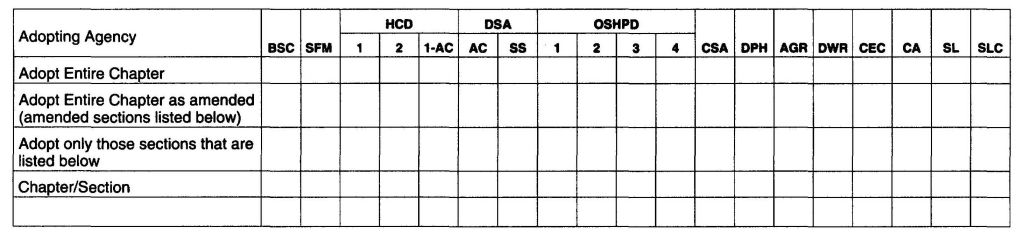
(The provisions contained in this appendix are not mandatory unless specifically referenced in the adopting ordinance.)
AF101.1 General. This appendix contains requirements for new construction in jurisdictions where radon-resistant construction is required.
Inclusion of this appendix by jurisdictions shall be determined through the use of locally available data or determination of Zone 1 designation in Figure AF101.
AF102.1 General. For the purpose of these requirements, the terms used shall be defined as follows:
SUBSLAB DEPRESSURIZATION SYSTEM (Passive). A system designed to achieve lower sub-slab air pressure relative to indoor air pressure by use of a vent pipe routed through the conditioned space of a building and connecting the sub-slab area with outdoor air, thereby relying on the convective flow of air upward in the vent to draw air from beneath the slab.
SUBSLAB DEPRESSURIZATION SYSTEM (Active). A system designed to achieve lower sub-slab air pressure relative to indoor air pressure by use of a fan-powered vent drawing air from beneath the slab.
DRAIN TILE LOOP. A continuous length of drain tile or perforated pipe extending around all or part of the internal or external perimeter of a basement or crawl space footing.
RADON GAS. A naturally-occurring, chemically inert, radioactive gas that is not detectable by human senses. As a gas, it can move readily through particles of soil and rock and can accumulate under the slabs and foundations of homes where it can easily enter into the living space through construction cracks and openings.
SOIL-GAS-RETARDER. A continuous membrane of 6-mil (0.15 mm) polyethylene or other equivalent material used to retard the flow of soil gases into a building.
SUBMEMBRANE DEPRESSURIZATION SYSTEM. A system designed to achieve lower-sub-membrane air pressure relative to crawl space air pressure by use of a vent drawing air from beneath the soil-gas-retarder membrane.
AF103.1 General. The following construction techniques are intended to resist radon entry and prepare the building for post-construction radon mitigation, if necessary (see Figure AF102). These techniques are required in areas where designated by the jurisdiction.
AF103.2 Subfloor preparation. A layer of gas-permeable material shall be placed under all concrete slabs and other floor systems that directly contact the ground and are within the walls of the living spaces of the building, to facilities future installation of a sub-slab depressurization system, if needed. The gas-permeable layer shall consist of one of the following:
AF103.3 Soil-gas-retarder. A minimum 6-mil (0.15 mm) [or 3-mil (0.075 mm) cross-laminated] polyethylene or equivalent flexible sheeting material shall be placed on top of the gas-permeable layer prior to casting the slab or placing the floor assembly to serve as a soil-gas-retarder by bridging any cracks that develop in the slab or floor assembly and to prevent concrete from entering the void spaces in the aggregate base material. The sheeting shall cover the entire floor area with separate sections of sheeting lapped at least 12 inches (305 mm). The sheeting shall fit closely around any pipe, wire or other penetrations of the material. All punctures or tears in the material shall be sealed or covered with additional sheeting.
AF103.4 Entry routes. Potential radon entry routes shall be closed in accordance with Sections AF103.4.1 through AF103.4.10.
AF103.4.1 Floor openings. Openings around bathtubs, showers, water closets, pipes, wires or other objects that penetrate concrete slabs or other floor assemblies shall be filled with a polyurethane caulk or equivalent sealant applied in accordance with the manufacture's recommendations.
AF103.4.2 Concrete joints. All control joints, isolation joints, construction joints and any other joints in concrete slabs or between slabs and foundation walls shall be sealed with a caulk or sealant. Gaps and joints shall be cleared of loose material and filled with polyurethane caulk or other elastometric sealant applied in accordance with the manufacture's recommendations.
AF103.4.3 Condensate drains. Condensate drains shall be trapped or routed through nonperforated pipe to daylight.
AF103.4.4 Sumps. Sump pits open to soil or serving as the termination point for sub-slab or exterior drain tile loops shall
599be covered with a gasketed or otherwise sealed lid. Sumps used as the suction point in a sub-slab depressurization system shall have a lid designed to accommodate the vent pipe. Sumps used as a floor drain shall have a lid equipped with a trapped inlet.
AF103.4.5 Foundation walls. Hollow block masonry foundation walls shall be constructed with either a continuous course of solid masonry, one course of masonry grouted solid, or a solid concrete beam at or above finished ground surface to prevent passage of air from the interior of the wall into the living space. Where a brick veneer or other masonry ledge is installed, the course immediately below that ledge shall be sealed. Joints, cracks or other openings around all penetrations of both exterior and interior surfaces of masonry block or wood foundation walls below the ground surface shall be filled with polyurethane caulk or equivalent sealant. Penetrations of concrete walls shall be filled.
AF103.4.6 Dampproofing. The exterior surfaces of portions of concrete and masonry block walls below the ground surface shall be dampproofed in accordance with Section R406 of this code.
AF103.4.7 Air-handling units. Air-handling units in crawl spaces shall be sealed to prevent air from being drawn into the unit.
Exception: Units with gasketed seams or units that are otherwise sealed by the manufacturer to prevent leakage.
AF103.4.8 Ducts. Ductwork passing through or beneath a slab shall be of seamless material unless the air-handling system is designed to maintain continuous positive pressure within such ducting. Joints in such ductwork shall be sealed to prevent air leakage.
Ductwork located in crawl spaces shall have all seams and joints sealed by closure systems in accordance with Section M1601.4.1.
AF103.4.9 Crawl space floors. Openings around all penetrations through floors above crawl spaces shall be caulked or otherwise filled to prevent air leakage.
AF103.4.10 Crawl space access. Access doors and other openings or penetrations between basements and adjoining crawl spaces shall be closed, gasketed or otherwise filled to prevent air leakage.
AF103.5 Passive submembrane depressurization system. In buildings with crawl space foundations, the following components of a passive sub-membrane depressurization system shall be installed during construction.
Exception: Buildings in which an approved mechanical crawl space ventilation system or other equivalent system is installed.
AF103.5.1 Ventilation. Crawl spaces shall be provided with vents to the exterior of the building. The minimum net area of ventilation openings shall comply with Section R408.1 of this code.
AF103.5.2 Soil-gas-retarder. The soil in crawl spaces shall be covered with a continuous layer of minimum 6-mil (0.15 mm) polyethylene soil-gas-retarder. The ground cover shall be lapped a minimum of 12 inches (305 mm) at joints and shall extend to all foundation walls enclosing the crawl space area.
AF103.5.3 Vent pipe. A plumbing tee or other approved connection shall be inserted horizontally beneath the sheeting and connected to a 3- or 4-inch-diameter (76 mm or 102 mm) fitting with a vertical vent pipe installed through the sheeting. The vent pipe shall be extended up through the building floors, terminate at least 12 inches (305 mm) above the roof in a location at least 10 feet (3048 mm) away from any window or other opening into the conditioned spaces of the building that is less than 2 feet (610 mm) below the exhaust point, and 10 feet (3048 mm) from any window or other opening in adjoining or adjacent buildings.
AF103.6 Passive subslab depressurization system. In basement or slab-on-grade buildings, the following components of a passive sub-slab depressurization system shall be installed during construction.
AF103.6.1 Vent pipe. A minimum 3-inch-diameter (76 mm) ABS, PVC or equivalent gas-tight pipe shall be embedded vertically into the sub-slab aggregate or other permeable material before the slab is cast. A “T” fitting or equivalent method shall be used to ensure that the pipe opening remains within the sub-slab permeable material. Alternatively, the 3-inch (76 mm) pipe shall be inserted directly into an interior perimeter drain tile loop or through a sealed sump cover where the sump is exposed to the sub-slab aggregate or connected to it through a drainage system.
The pipe shall be extended up through the building floors, terminate at least 12 inches (305 mm) above the surface of the roof in a location at least 10 feet (3048 mm) away from any window or other opening into the conditioned spaces of the building that is less than 2 feet (610 mm) below the exhaust point, and 10 feet (3048 mm) from any window or other opening in adjoining or adjacent buildings.
AF103.6.2 Multiple vent pipes. In buildings where interior footings or other barriers separate the sub-slab aggregate or other gas-permeable material, each area shall be fitted with an individual vent pipe. Vent pipes shall connect to a single vent that terminate separately above the roof.
AF103.7 Vent pipe drainage. All components of the radon vent pipe system shall be installed to provide positive drainage to the ground beneath the slab or soil-gas-retarder.
AF103.8 Vent pipe accessibility. Radon vent pipes shall be accessible for future fan installation through an attic or other area outside the habitable space.
Exception: The radon vent pipe need not be accessible in an attic space where an approved roof-top electrical supply is provided for future use.
AF103.9 Vent pipe identification. All exposed and visible interior radon vent pipes shall be identified with at least one label on each floor and in accessible attics. The label shall read: “Radon Reduction System.”
AF103.10 Combination foundations. Combination basement⁄crawl space or slab-on-grade⁄crawl space foundations shall have separate radon vent pipes installed in each type of
600foundation area. Each radon vent pipe shall terminate above the roof or shall be connected to a single vent that terminates above the roof.
AF103.11 Building depressurization. Joints in air ducts and plenums in unconditioned spaces shall meet the requirements of Section M1601. Thermal envelope air infiltration requirements shall comply with the energy conservation provisions in Chapter 11. Firestopping shall meet the requirements contained in Section R602.8.
AF103.12 Power source. To provide for future installation of an active sub-membrane or sub-slab depressurization system, an electrical circuit terminated in an approved box shall be installed during construction in the attic or other anticipated location of vent pipe fans. An electrical supply shall also be accessible in anticipated locations of system failure alarms.
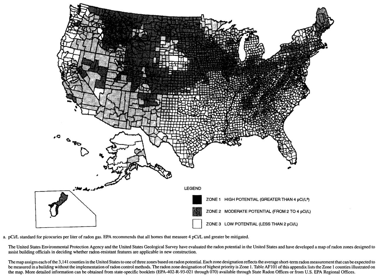
FIGURE AF101
EPA MAP OF RADON ZONES
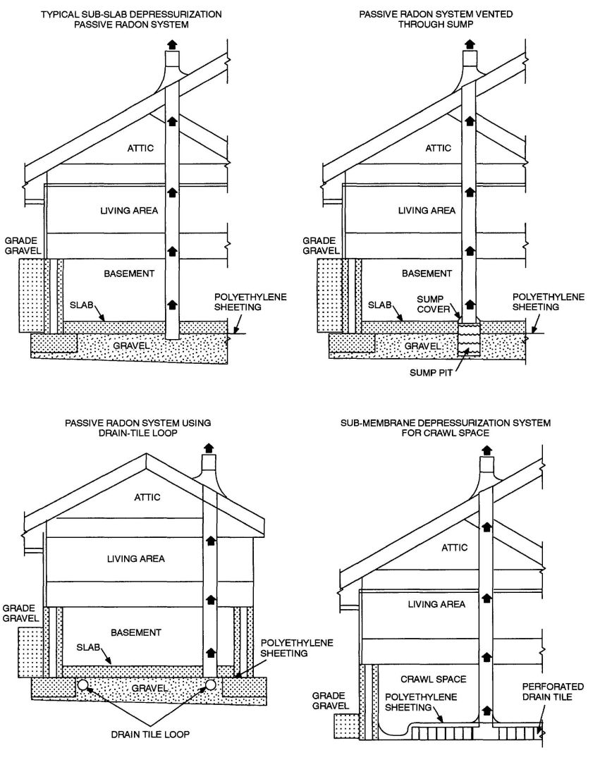
FIGURE AF102
RADON-RESISTANT CONSTRUCTION DETAILS FOR FOUR FOUNDATION TYPES
CALIFORNIA RESIDENTIAL CODE – MATRIX ADOPTION TABLE
APPENDIX G – SWIMMING POOLS, SPAS AND HOT TUBS
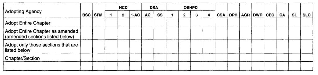
The provisions contained in this appendix are not mandatory unless specifically referenced in the adopting ordinance.
(Note: See Chapter 31, Section 3109 of the California Building Code, Title 24, Part 2.)
AG101.1 General. The provisions of this appendix shall control the design and construction of swimming pools, spas and hot tubs installed in or on the lot of a one- or two-family dwelling.
AG101.2 Pools in flood hazard areas. Pools that are located in flood hazard areas established by Table R301.2(1), including above-ground pools, on-ground pools and in-ground pools that involve placement of fill, shall comply with Sections AG101.2.1 or AG101.2.2.
Exception: Pools located in riverine flood hazard areas which are outside of designated floodways.
AG101.2.1 Pools located in designated floodways. Where pools are located in designated floodways, documentation shall be submitted to the building official, which demonstrates that the construction of the pool will not increase the design flood elevation at any point within the jurisdiction.
AG101.2.2 Pools located where floodways have not been designated. Where pools are located where design flood elevations are specified but floodways have not been designated, the applicant shall provide a floodway analysis that demonstrates that the proposed pool will not increase the design flood elevation more than 1 foot (305 mm) at any point within the jurisdiction.
AG102.1 General. For the purposes of these requirements, the terms used shall be defined as follows and as set forth in Chapter 2.
ABOVE-GROUND/ON-GROUND POOL. See “Swimming pool.”
BARRIER. A fence, wall, building wall or combination thereof which completely surrounds the swimming pool and obstructs access to the swimming pool.
HOT TUB. See “Swimming pool.”
IN-GROUND POOL. See “Swimming pool.”
RESIDENTIAL. That which is situated on the premises of a detached one- or two-family dwelling or a one-family townhouse not more than three stories in height.
SPA, NONPORTABLE. See “Swimming pool.”
SPA, PORTABLE. A nonpermanent structure intended for recreational bathing, in which all controls, water-heating and water-circulating equipment are an integral part of the product.
SWIMMING POOL. Any structure intended for swimming or recreational bathing that contains water over 24 inches (610 mm) deep. This includes in-ground, above-ground and on-ground swimming pools, hot tubs and spas.
SWIMMING POOL, INDOOR. A swimming pool which is totally contained within a structure and surrounded on all four sides by the walls of the enclosing structure.
SWIMMING POOL, OUTDOOR. Any swimming pool which is not an indoor pool.
AG103.1 In-ground pools. In-ground pools shall be designed and constructed in conformance with ANSI/NSPI-5 as listed in Section AG108.
AG103.2 Above-ground and on-ground pools. Above ground and on-ground pools shall be designed and constructed in conformance with ANSI/NSPI-4 as listed in Section AG108.
AG103.3 Pools in flood hazard areas. In flood hazard areas established by Table R301.2(1), pools in coastal high hazard areas shall be designed and constructed in conformance with ASCE 24.
AG104.1 Permanently installed spas and hot tubs. Permanently installed spas and hot tubs shall be designed and constructed in conformance with ANSI/NSPI-3 as listed in Section AG108.
AG104.2 Portable spas and hot tubs. Portable spas and hot tubs shall be designed and constructed in conformance with ANSI/NSPI-6 as listed in Section AG108.
AG105.1 Application. The provisions of this chapter shall control the design of barriers for residential swimming pools, spas and hot tubs. These design controls are intended to provide protection against potential drownings and near drownings by restricting access to swimming pools, spas and hot tubs.
AG105.2 Outdoor swimming pool. An outdoor swimming pool, including an in-ground, above-ground or on-ground pool, hot tub or spa shall be surrounded by a barrier which shall comply with the following:
609AG105.3 Indoor swimming pool. Walls surrounding an indoor swimming pool shall comply with Section AG105.2, Item 9.
AG105.4 Prohibited locations. Barriers shall be located to prohibit permanent structures, equipment or similar objects from being used to climb them.
AG105.5 Barrier exceptions. Spas or hot tubs with a safety cover which complies with ASTM F 1346, as listed in Section AG107, shall be exempt from the provisions of this appendix.
610AG106.1 General. Suction outlets shall be designed and installed in accordance with ANSI/APSP-7.
AG107.1 General.
ANSI—American National Standards Institute
11 West 42nd Street
New York, NY 10036
APSP—Association of Pool and Spa Professionals
NSPI—National Spa and Pool Institute
2111 Eisenhower Avenue
Alexandria, VA 22314
ASCE—American Society of Civil Engineers
1801 Alexander Bell Drive
Reston, VA 98411-0700
ASTM—ASTM International
100 Barr Harbor Drive,
West Conshohocken, PA 19428
UL—Underwriters Laboratories, Inc.
333 Pfingsten Road
Northbrook, IL 60062-2096
AG108.1 General.
ANSI/NSPI
ANSI/NSPI-3-99 Standard for
Permanently Installed Residential Spas AG104.1
ANSI/NSPI-4-99 Standard for Above-ground/
On-ground Residential Swimming Pools AG103.2
ANSI/NSPI-5-2003 Standard for
Residential In-ground Swimming Pools AG103.1
ANSI/NSPI-6-99 Standard for
Residential Portable Spas AG104.2
ANSI/APSP
ANSI/APSP-7-06 Standard for Suction Entrapment
avoidance in Swimming Pools, Wading Pools, Spas,
Hot Tubs and Catch Basins AG106.1
ASCE
ASCE/SEI-24-05 Flood Resistant
Design and Construction AG103.3
ASTM
ASTM F 1346-91 (2003) Performance
Specification for Safety Covers and Labeling
Requirements for All Covers for Swimming Pools,
Spas and Hot Tubs AG105.2, AG105.5
UL
UL 2017-2000 Standard for General-purpose
Signaling Devices and Systems—width Revisions through June 2004 AG105.2
| Adopting Agency | BSC | SFM | HCD | DSA | OSHPD | CSA | DPH | AGR | DWR | CEC | CA | SL | SLC | ||||||
|---|---|---|---|---|---|---|---|---|---|---|---|---|---|---|---|---|---|---|---|
| 1 | 2 | 1-AC | AC | SS | 1 | 2 | 3 | 4 | |||||||||||
| Adopt Entire Chapter | X | X | |||||||||||||||||
| Adopt Entire Chapter as amended (amended sections listed below) | |||||||||||||||||||
| Adopt Only those sections that are listed below | |||||||||||||||||||
| Chapter/Section | |||||||||||||||||||
AH101.1 Scope. Patio covers shall conform to the requirements of means of this appendix chapter.
Patio Covers. One-story structures not exceeding 12 feet (3657 mm) in height. Enclosure walls shall be permitted to be of any configuration, provided the open or glazed area of the longer wall and one additional wall is equal to at least 65 percent of the area below a minimum of 6 feet 8 inches (2032 mm) of each wall, measured from the floor. Openings shall be permitted to be enclosed with (1) insect screening, (2) approved translucent or transparent plastic not more than 0.125 inch (3.2 mm) in thickness, (3) glass conforming to the provisions of Section R308, or (4) any combination of the foregoing.
AH103.1 General. Patio covers shall be permitted to be detached from or attached to dwelling units. Patio covers shall be used only for recreational, outdoor living purposes and not as carports, garages, storage rooms or habitable rooms.
AH104.1 General. Patio covers shall be designed and constructed to sustain, within the stress limits of this code, all dead loads plus a minimum vertical live load of 10 pounds per square foot (0.48 kN/m2) except that snow loads shall be used where such snow loads exceed this minimum. Such covers shall be designed to resist the minimum wind loads set forth in Table R301.2(1).
AH105.1 General Exterior openings required for light and ventilation shall be permitted to open into a patio structure con-forming to Section AH101, provided that the patio structure shall be unenclosed if such openings are serving as emergency egress or rescue openings from sleeping rooms. Where such exterior openings, serve as an exit from the dwelling unit, the patio structures, unless unenclosed, shall be provided with exits conforming to the provisions of Section R310 of this code.
AH106.1 General. In areas with a frostline depth of zero as specified in Table R301.2(1), a patio cover shall be permitted to be supported on a slab on grade without footings, provided the slab conforms to the provisions of Section R506 of this code, is not less than 3.5 inches (89 mm) thick and the columns do not support live and dead loads in excess of 750 pounds (3.34 kN) per column.
AH107.1 General. Screen enclosures in hurricane-prone regions shall be in accordance with the provisions of this Section.
AH107.1.1 Habitable spaces. Screen enclosures shall not be considered habitable spaces.
AH107.1.2 Minimum ceiling height. Screen enclosures shall have a ceiling height of not less than 7 feet (2134 mm).
AH107.2 Definitions.
SCREEN ENCLOSURE. A building or part thereof, in whole or in part self-supporting, and having walls of insect screening and a roof of insect screening, plastic, aluminum, or similar lightweight material.
AH107.3 Screen enclosures.
AH107.3.1 Thickness. Actual wall thickness of extruded aluminum members shall be not less than 0.040 inches (1.02 mm).
AH107.3.2 Density. Screen density shall be a maximum of 20 threads per inch by 20 threads per inch mesh.
AH107.4 Design.
AH107.4.1 Wind load. Structural members supporting screen enclosures shall be designed to support minimum wind loads given in Table AH107.4(1) and AH107.4(2). Where any value is less than 10 psf (0.479 kN/m2) use 10 psf (0.479 kN/m2).
AH107.4.2 Deflection limit. For members supporting screen surfaces only, the total load deflection shall not exceed 1/60. Screen surfaces shall be permitted to include a maximum of 25 percent solid flexible finishers.
AH107.4.3 Importance factor. The wind factor for screen enclosures shall be 0.77 in accordance with Section 6.5.5 of ASCE 7.
615AH107.4.4 Roof live load. The minimum roof live load shall be 10 psf (0.479 kN/m2).
AH107.5 Footings. In areas with a frost line is zero, a screen enclosure shall be permitted to be supported on a concrete slab on grade without footings, provided the slab conforms to the provisions of Section R506, is not less than 3½ inches (89 mm) thick, and the columns do not support loads in excess of 750 pounds (3.36 kN) per column.
| LOAD CASE | WALL | Basic Wind Speed (mph) | |||||||||||
|---|---|---|---|---|---|---|---|---|---|---|---|---|---|
| 100 | 110 | 120 | 130 | 140 | 150 | ||||||||
| Exposure Category Design Pressure (psf) | |||||||||||||
| C | B | C | B | C | B | C | B | C | B | C | B | ||
| For SI: 1 mile per hour = 0.44 m/s, 1 pound per square foot = 0.0479 kPa, 1 foot = 304.8 mm. | |||||||||||||
| a. Values have been reduced for 0.77 Importance Factor in accordance with Section AH107.4.3. | |||||||||||||
| b. Minimum design pressure shall be 10 psf in accordance with Section AH107.4.1. | |||||||||||||
| c. Loads are applicable to screen enclosures with a mean roof height of 30 feet or less. For screen enclosures of different heights the pressures given shall be adjusted by multiplying the table pressure by the adjustment factor given in Table AH107.4(2). | |||||||||||||
| d. For Load Case A flow thru conditions the pressure given shall be applied simultaneously to both the upwind and downwind screen walls acting in the same direction as the wind. The structure shall also be analyzed for wind coming from the opposite direction. For the non-flow thru condition the screen enclosure wall should be analyzed for the load applied acting toward the interior of the enclosure. | |||||||||||||
| e. For Load Case B the table pressure multiplied by the projected frontal area of the screen enclosure is the total drag force, including drag on screen surfaces parallel to the wind, which must be transmitted to the ground. Use Load Case A for members directly supporting the screen surface perpendicular to the wind. Load Case B loads shall be applied only to structural members which carry wind loads from more than one surface. | |||||||||||||
| f. The roof structure shall be analyzed for the pressure given occurring both upward and downward. | |||||||||||||
| Ad | Windward and leeward walls (flow thru) and windward wall (non-flow thru) L/W = 0-1 | 12 | 8 | 14 | 10 | 17 | 12 | 19 | 14 | 23 | 16 | 26 | 18 |
| Ad | Windward and leeward walls (flow thru) and windward all (non-flow thru) L/W = 2 |
13 | 9 | 16 | 11 | 19 | 14 | 22 | 16 | 26 | 18 | 30 | 21 |
| Be | Windward: Non-gable roof | 16 | 12 | 20 | 14 | 24 | 17 | 28 | 20 | 32 | 23 | 37 | 26 |
| Be | Windward: Gable roof | 22 | 16 | 27 | 19 | 32 | 23 | 38 | 27 | 44 | 31 | 50 | 36 |
| ROOF | |||||||||||||
| Allf | Roof-screen | 4 | 3 | 5 | 4 | 6 | 4 | 7 | 5 | 8 | 6 | 9 | 7 |
| Allf | Roof-solid | 12 | 9 | 15 | 11 | 18 | 13 | 21 | 15 | 24 | 17 | 28 | 20 |
| MEAN | EXPOSURE | |
|---|---|---|
| Roof Height (ft) | B | C |
| For SI = 304.8 mm. | ||
| 15 | 1 | 0.86 |
| 20 | 1 | 0.92 |
| 25 | 1 | 0.96 |
| 30 | 1 | 1.00 |
| 35 | 1.05 | 1.03 |
| 40 | 1.09 | 1.06 |
| 45 | 1.12 | 1.09 |
| 50 | 1.16 | 1.11 |
| 55 | 1.19 | 1.14 |
| 60 | 1.22 | 1.16 |
CALIFORNIA RESIDENTIAL CODE–MATRIX ADOPTION TABLE
APPENDIXI–PRIVATE SEWAGE DISPOSAL
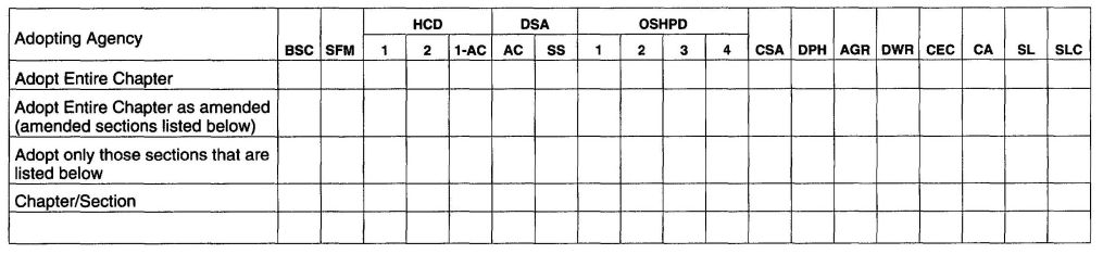
The provisions contained in this appendix are not mandatory unless specifically referenced in the adopting ordinance.
A1101.1 Scope. Private sewage disposal systems shall conform to the International Private Sewage Disposal Code.
619 620CALIFORNIA RESIDENTIAL CODE - MATRIX ADOPTION TABLE
APPENDIX J - EXISTING BUILDINGS AND STRUCTURES

The provisions contained in this appendix are not mandatory unless specifically referenced in the adopting ordinance.
AJ101.1 General. The purpose of these provisions is to encourage the continued use or reuse of legally existing buildings and structures. These provisions are intended to permit work in existing buildings that is consistent with the purpose of the International Residential Code. Compliance with these provisions shall be deemed to meet the requirements of the International Residential Code.
AJ101.2 Classification of work. For purposes of this appendix, all work in existing buildings shall be classified into the categories of repair, renovation, alteration and reconstruction. Specific requirements are established for each category of work in these provisions.
AJ101.3 Multiple categories of work. Work of more than one category may be part of a single work project. All related work permitted within a 12-month period shall be considered a single work project. Where a project includes one category of work in one building area and another category of work in a separate and unrelated area of the building, each project area shall comply with the requirements of the respective category of work. Where a project with more than one category of work is performed in the same area or in related areas of the building, the project shall comply with the requirements of the more stringent category of work.
AJ102.1 General. Regardless of the category of work being performed, the work shall not cause the structure to become unsafe or adversely affect the performance of the building; shall not cause an existing mechanical or plumbing system to become unsafe, hazardous, insanitary or overloaded; and unless expressly permitted by these provisions, shall not make the building any less conforming to this code or to any previously approved alternative arrangements than it was before the work was undertaken.
AJ102.2 Requirements by category of work. Repairs shall conform to the requirements of Section AJ301. Renovations shall conform to the requirements of Section AJ401. Alterations shall conform to the requirements of Section AJ501 and the requirements for renovations. Reconstructions shall conform to the requirements of Section AJ601 and the requirements for alterations and renovations.
AJ102.3 Smoke detectors. Regardless of the category of work, smoke detectors shall be provided where required by Section R314.3.1.
AJ102.4 Replacement windows. Regardless of the category of work, when an existing window, including sash and glazed portion is replaced, the replacement window shall comply with the requirements of Chapter 11.
AJ102.5 Flood hazard areas. Work performed in existing buildings located in a flood hazard area as established by Table R301.2(1) shall be subject to the provisions of Section R105.3.1.1.
AJ102.6 Equivalent alternatives. These provisions are not intended to prevent the use of any alternate material, alternate design or alternate method of construction not specifically prescribed herein, provided any alternate has been deemed to be equivalent and its use authorized by the building official.
AJ102.7 Other alternatives. Where compliance with these provisions or with this code as required by these provisions is technically infeasible or would impose disproportionate costs because of structural, construction or dimensional difficulties, other alternatives may be accepted by the building official. These alternatives may include materials, design features and/or operational features.
AJ102.8 More restrictive requirements. Buildings or systems in compliance with the requirements of this code for new construction shall not be required to comply with the any more restrictive requirement of these provisions.
AJ102.9 Features exceeding International Residential Code requirements. Elements, components and systems of existing buildings with features that exceed the requirements of this code for new construction, and are not otherwise required as part of approved alternative arrangements or deemed by the building official to be required to balance other building elements not complying with this code for new construction, shall not be prevented by these provisions from being modified as long as they remain in compliance with the applicable requirements for new construction.
AJ103.1 General. If a building permit is required at the request of the prospective permit applicant, the building official or his designee shall meet with the prospective applicant to discuss plans for any proposed work under these provisions prior to the application for the permit. The purpose of this preliminary meeting is for the building official to again an understanding of the prospective applicant’s intentions for the proposed work, and to determine, together with the prospective applicant, the specific applicability of these provisions.
AJ104.1 General. The building official may require an existing building to be investigated and evaluated by a registered
623design professional in the case of proposed reconstruction of any portion of a building. The evaluation shall determine the existence of any potential nonconformities with these provisions, and shall provide a basis for determining the impact of the proposed changes on the performance of the building. The evaluation shall use the following sources of information, as applicable:
Exception: Detached one- or two-family dwellings that are not irregular buildings under Section R301.2.2.2.5 and are not undergoing an extensive reconstruction shall not be required to be evaluated.
AJ105.1 Identification of work area. The work area shall be clearly identified on all permits issued under these provisions.
AJ201.1 General. For purposes of this appendix, the terms used are defined as follows.
ALTERATION. The reconfiguration of any space, the addition or elimination of any door or window, the reconfiguration or extension of any system, or the installation of any additional equipment.
CATEGORIES OF WORK. The nature and extent of construction work undertaken in an existing building. The categories of work covered in this Appendix, listed in increasing order of stringency of requirements, are repair, renovation, alteration and reconstruction.
DANGEROUS. Where the stresses in any member; the condition of the building, or any of its components or elements or attachments; or other condition that results in an overload exceeding 150 percent of the stress allowed for the member or material in this code.
EQUIPMENT OR FIXTURE. Any plumbing, heating, electrical, ventilating, air conditioning, refrigerating and fire protection equipment, and elevators, dumb waiters, boilers, pressure vessels, and other mechanical facilities or installations that are related to building services.
LOAD-BEARING ELEMENT. Any column, girder, beam, joist, truss, rafter, wall, floor or roof sheathing that supports any vertical load in addition to its own weight, and/or any lateral load.
MATERIALS AND METHODS REQUIREMENTS. Those requirements in this code that specify material standards; details of installation and connection; joints; penetrations; and continuity of any element, component or system in the building. The required quantity, fire resistance, flame spread, acoustic or thermal performance, or other performance attribute is specifically excluded from materials and methods requirements.
RECONSTRUCTION. The reconfiguration of a space that affects an exit, a renovation and/or alteration when the work area is not permitted to be occupied because existing means of egress and fire protection systems, or their equivalent, are not in place or continuously maintained; and/or there are extensive alterations as defined in Section AJ501.3.
REHABILITATION. Any repair, renovation, alteration or reconstruction work undertaken in an existing building.
RENOVATION. The change, strengthening or addition of load-bearing elements; and/or the refinishing, replacement, bracing, strengthening, upgrading or extensive repair of existing materials, elements, components, equipment and/or fixtures. Renovation involves no reconfiguration of spaces. Interior and exterior painting are not considered refinishing for purposes of this definition, and are not renovation.
REPAIR. The patching, restoration and/or minor replacement of materials, elements, components, equipment and/or fixtures for the purposes of maintaining those materials, elements, components, equipment and/or fixtures in good or sound condition.
WORK AREA. That portion of a building affected by any renovation, alteration or reconstruction work as initially intended by the owner and indicated as such in the permit. Work area excludes other portions of the building where incidental work entailed by the intended work must be performed, and portions of the building where work not initially intended by the owner is specifically required by these provisions for a renovation, alteration or reconstruction.
AJ301.1 Materials. Except as otherwise required herein, work shall be done using like materials or materials permitted by this code for new construction.
AJ301.1.1 Hazardous materials. Hazardous materials no longer permitted, such as asbestos and lead-based paint, shall not be used.
AJ301.1.2 Plumbing materials and supplies. The following plumbing materials and supplies shall not be used:
AJ301.2 Water closets. When any water closet is replaced with a newly manufactured water closet, the replacement water closet shall comply with the requirements of Section P2903.2.
AJ301.3 Safety glazing. Replacement glazing in hazardous locations shall comply with the safety glazing requirements of Section R308.1.
624AJ301.4 Electrical. Repair or replacement of existing electrical wiring and equipment undergoing repair with like material shall be permitted.
Exceptions:
- Replacement of electrical receptacles shall comply with the requirements of Chapters 34 through 43.
- Plug fuses of the Edison-base type shall be used for replacement only where there is no evidence of overfusing or tampering per the applicable requirements of Chapters 34 through 43.
- For replacement of nongrounding-type receptacles with grounding-type receptacles and for branch circuits that do not have an equipment grounding conductor in the branch circuitry, the grounding conductor of a grounding type receptacle outlet shall be permitted to be grounded to any accessible point on the grounding electrode system, or to any accessible point on the grounding electrode conductor, as allowed and described in Chapters 34 through 43.
AJ401.1 Materials and methods. The work shall comply with the materials and methods requirements of this code.
AJ401.2 Door and window dimensions. Minor reductions in the clear opening dimensions of replacement doors and windows that result from the use of different materials shall be allowed, whether or not they are permitted by this code.
AJ401.3 Interior finish. Wood paneling and textile wall coverings used as an interior finish shall comply with the flame spread requirements of Section R302.9.
AJ401.4 Structural. Unreinforced masonry buildings located in Seismic Design Category D2 or E shall have parapet bracing and wall anchors installed at the roofline whenever a reroofing permit is issued. Such parapet bracing and wall anchors shall be of an approved design.
AJ501.1 Newly constructed elements. Newly constructed elements, components and systems shall comply with the requirements of this code.
Exceptions:
- Openable windows may be added without requiring compliance with the light and ventilation requirements of Section R303.
- Newly installed electrical equipment shall comply with the requirements of Section AJ501.5.
AJ501.2 Nonconformities. The work shall not increase the extent of noncompliance with the requirements of Section AJ601, or create nonconformity with those requirements which did not previously exist.
AJ501.3 Extensive alterations. When the total area of all the work areas included in an alteration exceeds 50 percent of the area of the dwelling unit, the work shall be considered as a reconstruction and shall comply with the requirements of these provisions for reconstruction work.
Exception: Work areas in which the alteration work is exclusively plumbing, mechanical or electrical shall not be included in the computation of total area of all work areas.
AJ501.4 Structural. The minimum design loads for the structure shall be the loads applicable at the time the building was constructed, provided that no dangerous condition is created. Structural elements that are uncovered during the course of the alteration and that are found to be unsound or dangerous shall be made to comply with the applicable requirements of this code.
AJ501.5 Electrical equipment and wiring.
AJ501.5.1 Materials and methods. Newly installed electrical equipment and wiring relating to work done in any work area shall comply with the materials and methods requirements of Chapters 34 through 43.
Exception: Electrical equipment and wiring in newly installed partitions and ceilings shall comply with all applicable requirements of Chapters 34 through 43.
AJ501.5.2 Electrical service. Service to the dwelling unit shall be a minimum of 100 ampere, three-wire capacity and service equipment shall be dead front having no live parts exposed that could allow accidental contact. Type “S” fuses shall be installed when fused equipment is used.
Exception: Existing service of 60 ampere, three-wire capacity, and feeders of 30 ampere or larger two- or three-wire capacity shall be accepted if adequate for the electrical load being served.
AJ501.5.3 Additional electrical requirements. When the work area includes any of the following areas within a dwelling unit, the requirements of Sections AJ501.5.3.1 through AJ501.5.3.5 shall apply.
AJ501.5.3.1 Enclosed areas. Enclosed areas other than closets, kitchens, basements, garages, hallways, laundry areas and bathrooms shall have a minimum of two duplex receptacle outlets, or one duplex receptacle outlet and one ceiling or wall type lighting outlet.
AJ501.5.3.2 Kitchen and laundry areas. Kitchen areas shall have a minimum of two duplex receptacle outlets. Laundry areas shall have a minimum of one duplex receptacle outlet located near the laundry equipment and installed on an independent circuit.
AJ501.5.3.3 Ground-fault circuit-interruption. Ground fault circuit interruption shall be provided on newly installed receptacle outlets if required by Chapters 34 through 43.
AJ501.5.3.4 Lighting outlets. At least one lighting outlet shall be provided in every bathroom, hallway, stairway, attached garage and detached garage with electric power to illuminate outdoor entrances and exits, and in
625utility rooms and basements where these spaces are used for storage or contain equipment requiring service.
AJ501.5.3.5 Clearance. Clearance for electrical service equipment shall be provided in accordance with Chapters 34 through 43.
AJ501.6 Ventilation. All reconfigured spaces intended for occupancy and all spaces converted to habitable or occupiable space in any work area shall be provided with ventilation in accordance with Section R303.
AJ501.7 Ceiling height. Habitable spaces created in existing basements shall have ceiling heights of not less than 6 feet 8 inches (2032 mm). Obstructions may project to within 6 feet 4 inches (1930 mm) of the basement floor. Existing finished ceiling heights in nonhabitable spaces in basements shall not be reduced.
AJ501.8 Stairs.
AJ501.8.1 Stair width. Existing basement stairs and handrails not otherwise being altered or modified shall be permitted to maintain their current clear width at, above, and below existing handrails.
AJ501.8.2 Stair headroom. Headroom height on existing basement stairs being altered or modified shall not be reduced below the existing stairway finished headroom. Existing basement stairs not otherwise being altered shall be permitted to maintain the current finished headroom.
AJ501.8.3 Stair landing. Landings serving existing basement stairs being altered or modified shall not be reduced below the existing stairway landing depth and width. Existing basement stairs not otherwise being altered shall be permitted to maintain the current landing depth and width.
AJ601.1 Stairways, handrails and guards.
AJ601.1.1 Stairways. Stairways within the work area shall be provided with illumination in accordance with Section R303.6.
AJ601.1.2 Handrails. Every required exit stairway that has four or more risers, is part of the means of egress for any work area, and is not provided with at least one handrail, or in which the existing handrails are judged to be in danger of collapsing, shall be provided with handrails designed and installed in accordance with Section R311 for the full length of the run of steps on at least one side.
AJ601.1.3 Guards. Every open portion of a stair, landing or balcony that is more than 30 inches (762 mm) above the floor or grade below, is part of the egress path for any work area, and does not have guards or in which the existing guards are judged to be in danger of collapsing, shall be provided with guards designed and installed in accordance with Section R312.
AJ601.2 Wall and ceiling finish. The interior finish of walls and ceilings in any work area shall comply with the requirements of Section R302.9. Existing interior finish materials that do not comply with those requirements shall be removed or shall be treated with an approved fire-retardant coating in accordance with the manufacturer’s instructions to secure compliance with the requirements of this section.
AJ601.3 Separation walls. Where the work area is in an attached dwelling unit, walls separating dwelling units that are not continuous from the foundation to the underside of the roof sheathing shall be constructed to provide a continuous fire separation using construction materials consistent with the existing wall or complying with the requirements for new structures. Performance of work shall be required only on the side of the wall of the dwelling unit that is part of the work area.
AJ601.4 Ceiling height. Habitable spaces created in existing basements shall be permitted to have ceiling heights of not less than 6 feet 8 inches (2032 mm). Obstructions may project to within 6 feet 4 inches (1930 mm) of the basement floor. Existing finished ceiling heights in nonhabitable spaces in basements shall not be reduced.
626CALIFORNIA RESIDENTAL CODE - MATRIX ADOPTION TABLE
APPENDIX K - SOUND TRANSMISSION
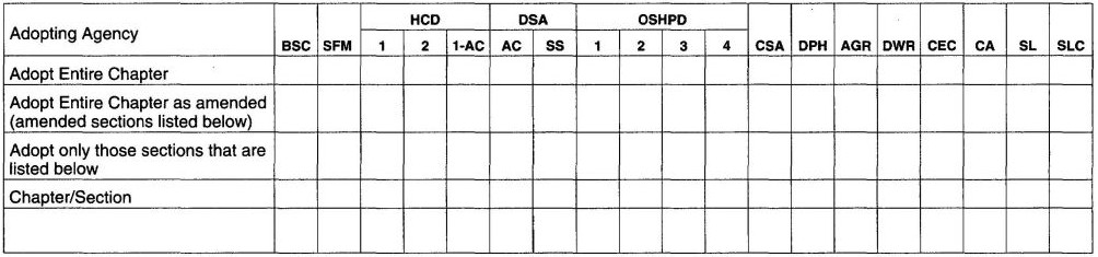
The provisions contained in this appendix are not mandatory unless specifically referenced in the adopting ordinance.
(Note: See Section 1207 “Sound Transmission” of the California Building Code, Title 24, Part 2, for requirements applicable to structures in this code.)
AK101.1 General. Wall and floor-ceiling assemblies separating dwelling units including those separating adjacent townhouse units shall provide air-borne sound insulation for walls, and both air-borne and impact sound insulation for floor-ceiling assemblies.
AK102.1 General. Air-borne sound insulation for wall and floor-ceiling assemblies shall meet a Sound Transmission Class (STC) rating of 45 when tested in accordance with ASTM E 90. Penetrations or openings in construction assemblies for piping; electrical devices; recessed cabinets; bathtubs; soffits; or heating, ventilating or exhaust ducts shall be sealed, lined, insulated or otherwise treated to maintain the required ratings. Dwelling unit entrance doors, which share a common space, shall be tight fitting to the frame and sill.
AK102.1.1 Masonry. The sound transmission class of concrete masonry and clay masonry assemblies shall be calculated in accordance with TMS 0302 or determined through testing in accordance with ASTM E 90.
AK103.1 General. Floor/ceiling assemblies between dwelling units or between a dwelling unit and a public or service area within a structure shall have an Impact Insulation Class (IIC) rating of not less than 45 when tested in accordance with ASTM E 492.
| ASTM E 90-04 Test Method for Laboratory Measurement of Airborne Sound Transmission Loss of Building Partitions and Elements. | AK102 | |
| ASTM E 492-04 Specification for Laboratory Measurement of Impact Sound Transmission through Floor-ceiling Assemblies Using the Tapping Machine. | AK103 | |
| The Masonry Society | ||
| TMS 0302-07 Standard for Determining the Sound Transmission Class Rating for Masonry Walls. |
AK102.1.1 | |
CALIFORNIA RESIDENTIAL CODE – MATRIX ADOPTION TABLE
APPENDIX L – PERMIT FEES
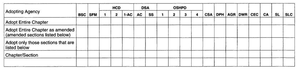
The provisions contained in this appendix are not mandatory unless specifically referenced in the adopting ordinance.
| TOTAL VALUATION | FEE |
|---|---|
| $1 to $500 | $24 |
| $501 to $2,000 | $24 for the first $500; plus $3 for each additional $100 or fraction thereof, to and including $2,000 |
| $2,001 to $40,000 | $69 for the first $2,000; plus $11 for each additional $1,000 or fraction thereof, to and including $40,000 |
| $40,001, to $100,000 | $487 for the first $40,000; plus $9 for each additional $1,000 or fraction thereof, to and including $100,00 |
| $100,00, to $500,000 | $1,027 for the first $100,000; plus $7 for each additional $1,000 or fraction thereof, to and including $500,000 |
| $500,001 to $1,000,000 | $3,827 for the first $500,000; plus $5 for each additional $1,000 or fraction thereof, to and including $5,000,000 |
| $1,000,001 to $5,000,000 | $6,327 for the first $1,000,000; plus $3 for each additional $1,000 of fraction thereof, to and including $5,000,000 |
| $5,000,001 and over | $18,327 for the first $5,000,000; plus $1 for each additional $1,000 or fraction thereof |
CALIFORNIA RESIDENTIAL CODE - MATRIX ADOPTION TABLE
APPENDIX M - HOME DAY CARE-R-3 OCCUPANCY
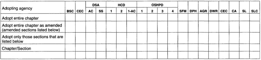
See Health and Safety Code Sections 1597.45, 1597.46, 1597.54 and 13143 regarding small family day-care homes and large family day-care homes. Provisions for day-care facilities shall be in accordance with Section 1.1.3.1 for classification, R326 for large family day-care, R325 for Group R-3.1 or the California Building Code. This appendix is not applicable in California.
637 638CALIFORNIA RESIDENTIAL CODE – MATRIX ADOPTION TABLE
APPENDIX N – VENTING METHODS
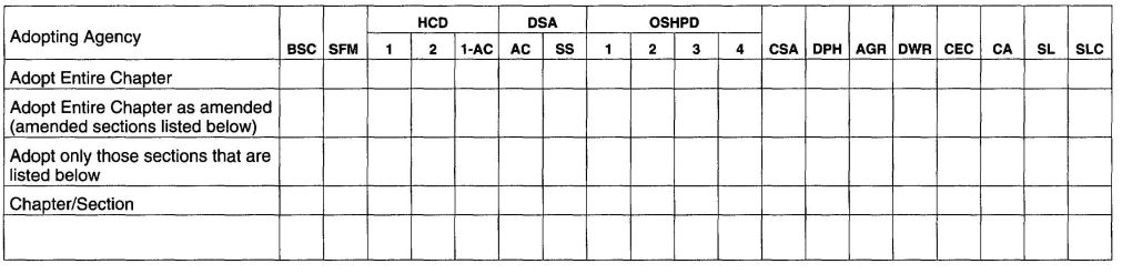
(This appendix is informative and is not part of the code.
This appendix provides examples of various of venting methods.)
The provisions contained in this appendix are not mandatory unless specifically referenced in the adopting ordinance.
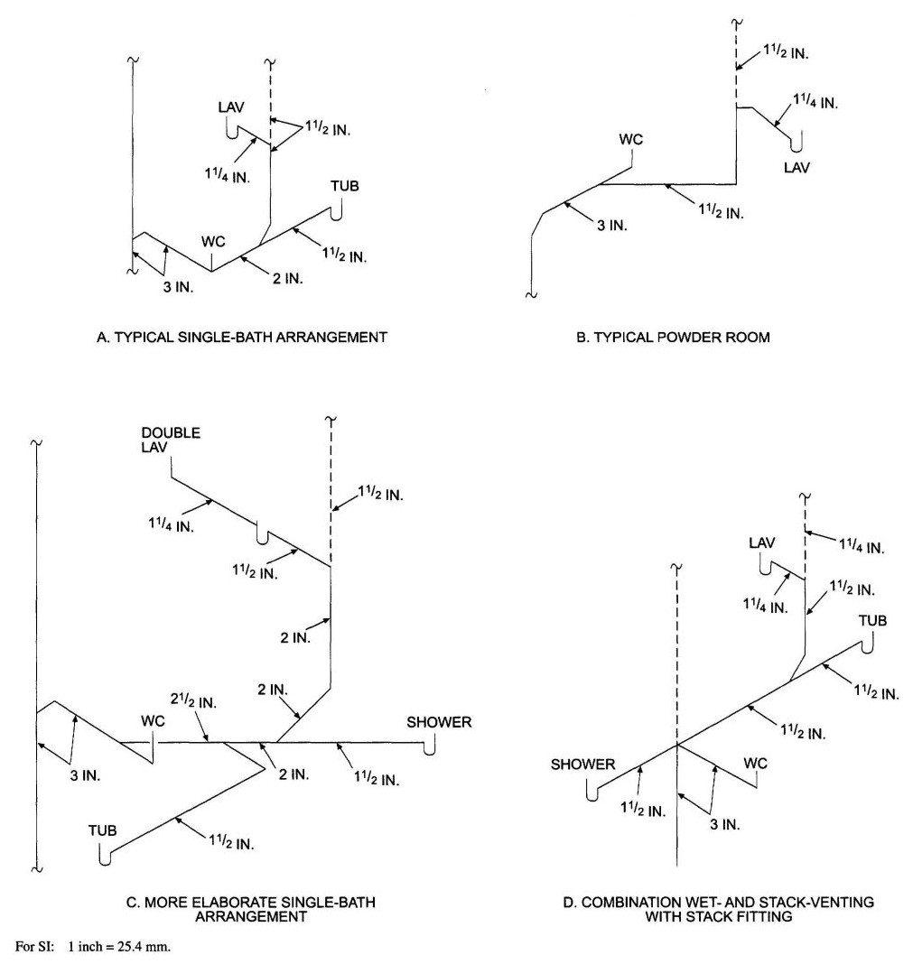
FIGURE N1
TYPICAL SINGLE-BATH WET-VENT ARRANGEMENTS
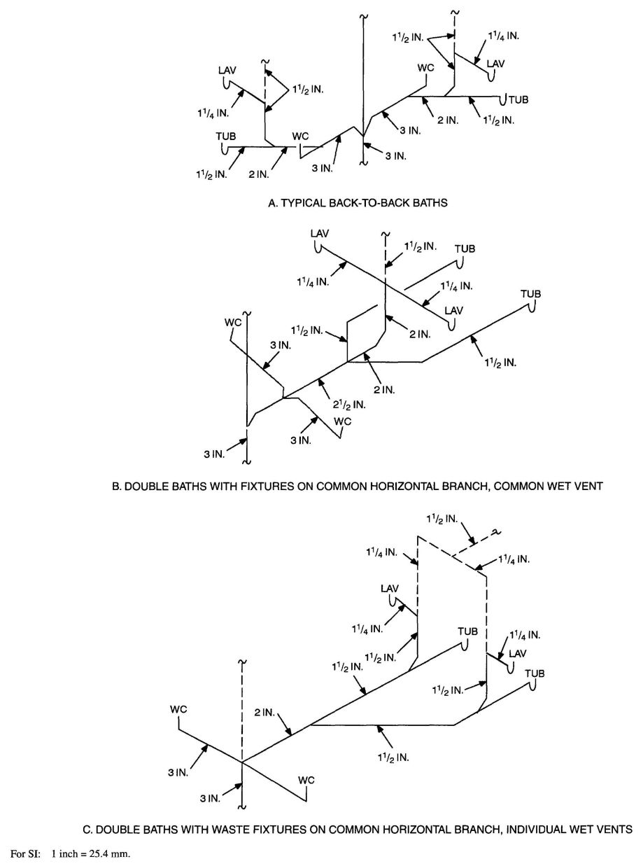
FIGURE N2
TYPICAL DOUBLE-BATH WET-VENT ARRANGEMENTS
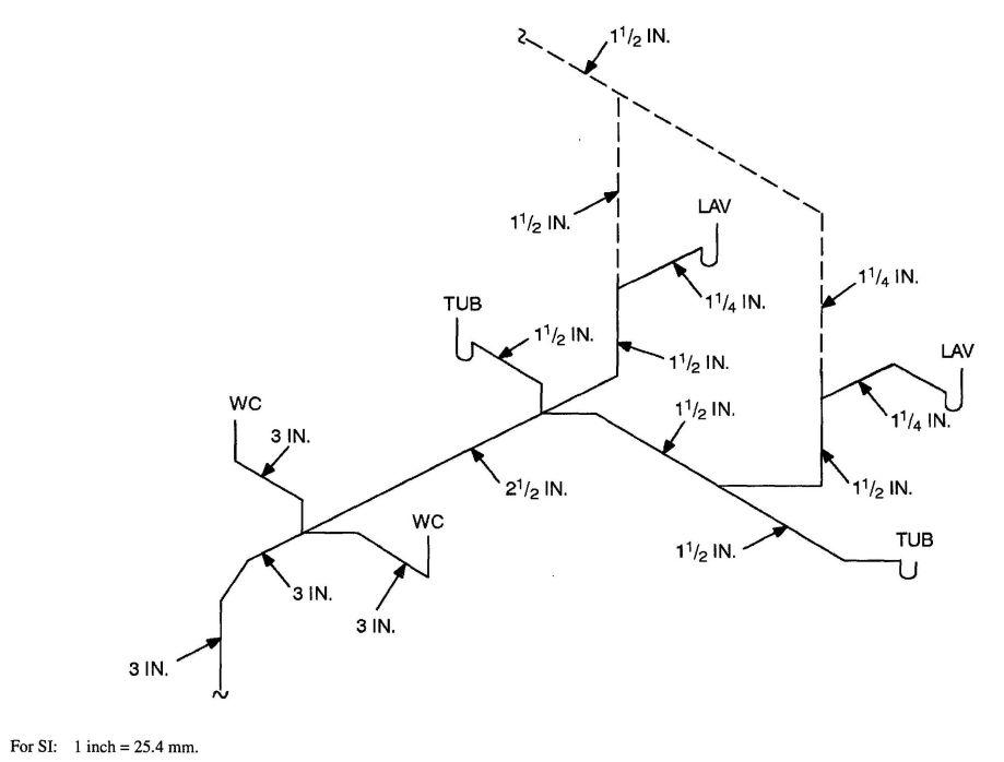
FIGURE N3
TYPICAL HORIZONTAL WET VENTING
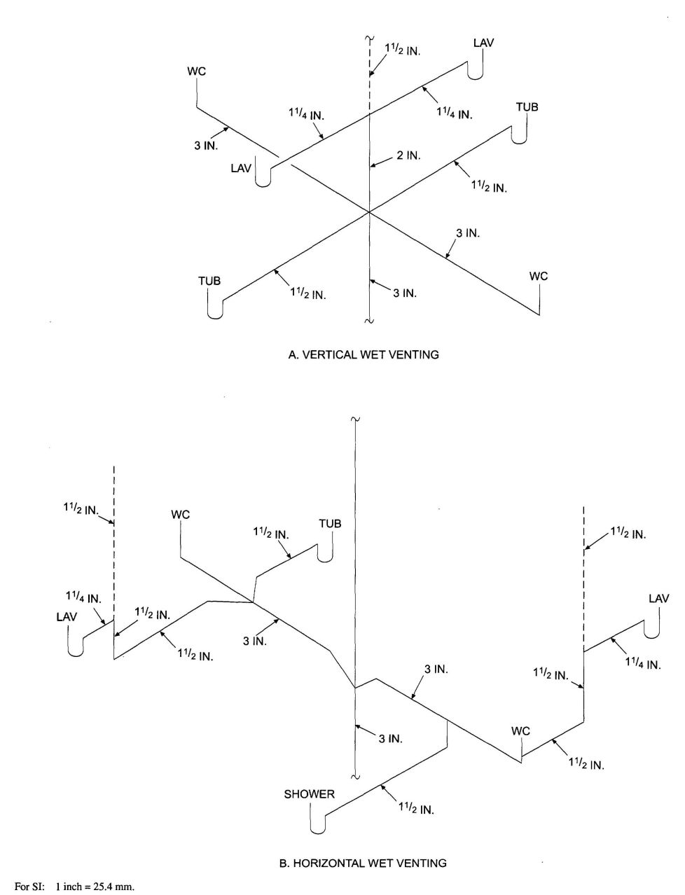
FIGURE N4
TYPICAL METHODS OF WET VENTING
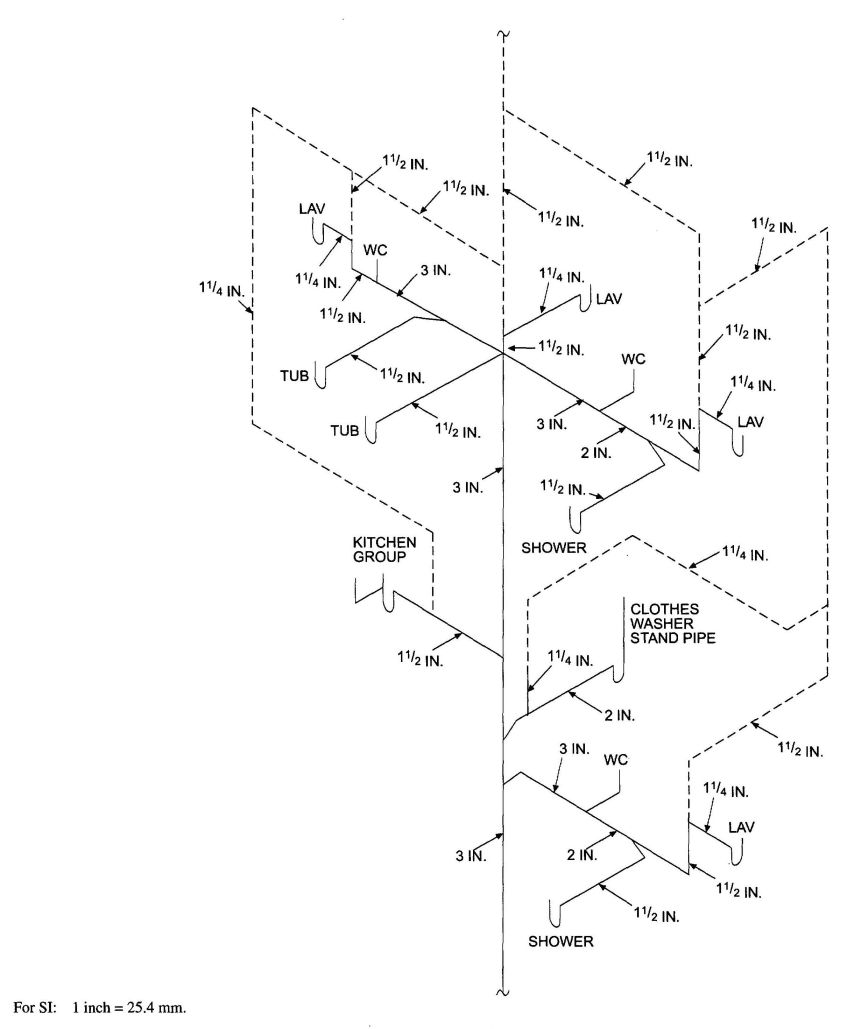
FIGURE N5
SINGLE STACK SYSTEM FOR A TWO-STORY DWELLING
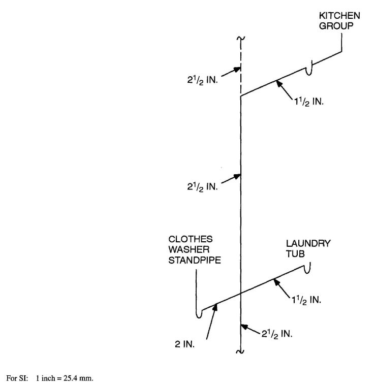
FIGURE N6
WASTE STACK VENTING
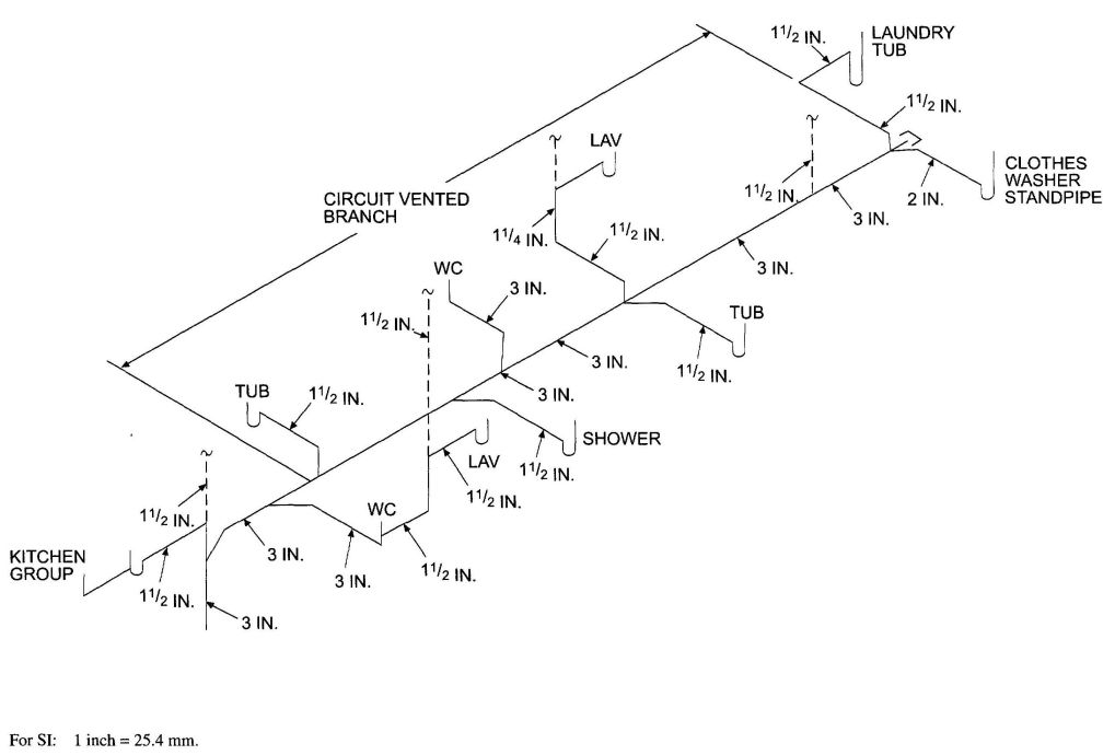
FIGURE N7
CIRCUIT VENT WITH ADDITIONAL NONCIRCUIT VENTED BRANCH
CALIFORNIA RESIDENTIAL CODE – MATRIX ADOPTION TABLE
APPENDIX O – GRAY WATER RECYCLING SYSTEMS
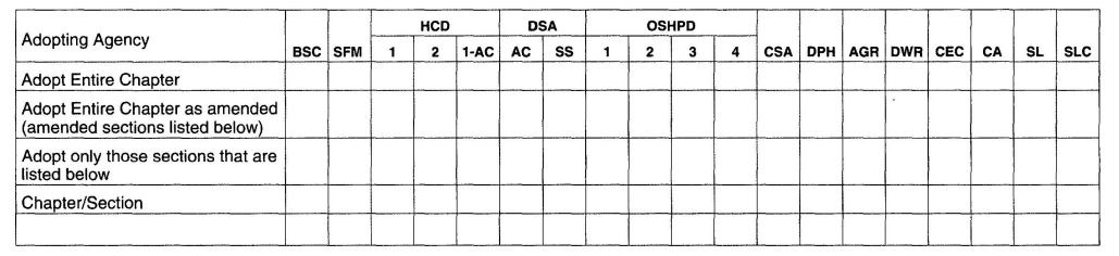
The provisions contained in this appendix are not mandatory unless specifically referenced in the adopting ordinance.
Note: Section P2601.2 of the International Residential Code requires all plumbing fixtures that receive water or waste to discharge to the sanitary drainage system of the structure. To allow for the use of a gray water recycling system, Section P2601.2 of the International Residential Code should be revised to read as follows:
P2601.2 Connections. Plumbing fixtures, drains and appliances used to receive or discharge liquid waste or sewage shall be directly connected to the sanitary drainage system of the building or premises, in accordance with the requirements of this code. This section shall not be construed to prevent indirect waste systems.
Exception: Bathtubs, showers, lavatories, clothes washers and laundry trays are not required to discharge to the sanitary drainage system where those fixtures discharge to an approved gray water recycling system.
AO101.1 Scope. The provisions of this appendix shall govern the materials, design, construction and installation of gray water systems for flushing of water closets and urinals and for subsurface landscape irrigation [see Figures AO101.1(1) and AO101.1(2)].
AO101.2 Definition. The following term shall have the meaning shown herein.
GRAY WATER. Waste discharged from lavatories, bathtubs, showers, clothes washers and laundry trays.
AO101.3 Permits. Permits shall be required in accordance with Section R105 of the International Residential Code.
AO101.4 Installation. In addition to the provisions of Section AO101, systems for flushing of water closets and urinals shall comply with Section AO102 and systems for subsurface landscape irrigation shall comply with Section AO103. Except as provided for in Appendix O, all systems shall comply with the provisions of the International Residential Code.
AO101.5 Materials. Above-ground drain, waste and vent piping for gray water systems shall conform to one of the standards listed in Table P3002.1(1) of the International Residential Code. Gray water underground building drainage and vent pipe shall conform to one of the standards listed in Table P3002.1(2) of the International Residential Code.
AO101.6 Tests. Drain, waste and vent piping for gray water systems shall be tested in accordance with Section P2503 of the International Residential Code.
AO101.7 Inspections. Gray water systems shall be inspected in accordance with Section P2503 of the International Residential Code.
AO101.8 Potable water connections. Only connections in accordance with Section AO102.3 shall be made between a gray water recycling system and a potable water system.
AO101.9 Waste water connections. Gray water recycling systems shall receive the waste discharge only of bathtubs, showers, lavatories, clothes washers and laundry trays.
AO101.10 Filtration. Gray water entering the reservoir shall pass through an approved filter such as a media, sand or diatomaceous earth filter.
AO101.10.1 Required valve. A full-open valve shall be installed downstream of the last fixture connection to the gray water discharge pipe before entering the required filter.
AO101.11 Collection reservoir. Gray water shall be collected in an approved reservoir constructed of durable, nonabsorbent and corrosion-resistant materials. The reservoir shall be a closed and gas-tight vessel. Access openings shall be provided to allow inspection and cleaning of the reservoir interior.
AO101.12 Overflow. The collection reservoir shall be equipped with an overflow pipe of the same diameter as, or larger than, the influent pipe for the gray water. The overflow pipe shall be trapped and shall be indirectly connected to the sanitary drainage system.
AO101.13 Drain. A drain shall be located at the lowest point of the collection reservoir and shall be indirectly connected to the sanitary drainage system. The drain shall be the same diameter as the overflow pipe required in Section AO101.12.
AO101.14 Vent required. The reservoir shall be provided with a vent sized in accordance with Chapter 31 of the International Residential Code and based on the diameter of the reservoir influent pipe.
AO102.1 Collection reservoir. The holding capacity of the reservoir shall be a minimum of twice the volume of water required to meet the daily flushing requirements of the fixtures supplied with gray water, but not less than 50 gallons (189 L). The reservoir shall be sized to limit the retention time of gray water to a maximum of 72 hours.
AO102.2 Disinfection. Gray water shall be disinfected by an approved method that uses one or more disinfectants such as chlorine, iodine or ozone that are recommended for use with the pipes, fittings and equipment by the manufacturer of the pipes, fittings and equipment.
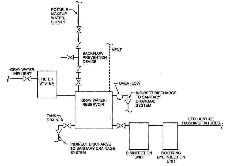
FIGURE AO101.1(1)
GRAY WATER RECYCLING SYSTEM FOR FLUSHING WATER CLOSETS AND URINALS
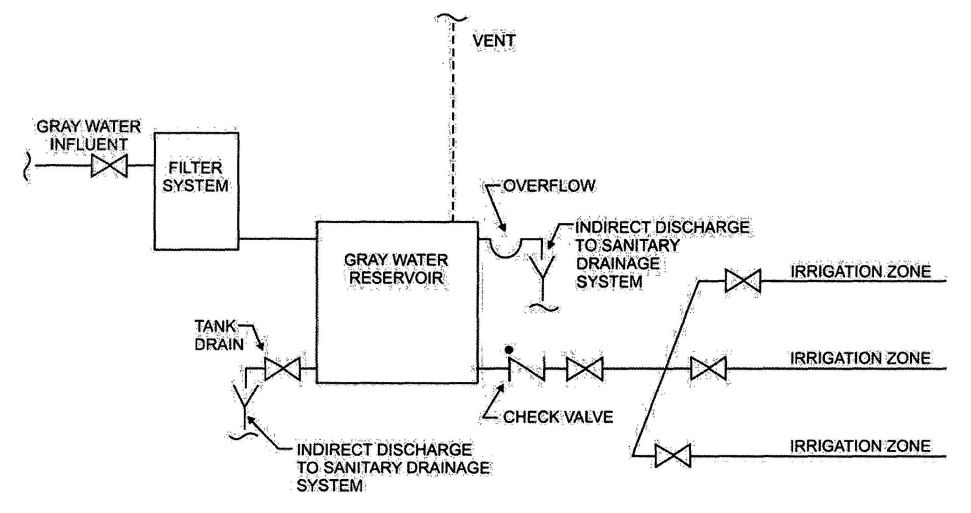
FIGURE AO101.1(2)
GRAY WATER RECYCLING SYSTEM FOR SUBSURFACE LANDSCAPE IRRIGATION
AO102.3 Makeup water. Portable water shall be supplied as a source of makeup water for the gray water system. The portable water supply shall be protected against backflow in accordance with Section P2902 of the International Residential Code. A full-open valve shall be located on the makeup water supply line to the collection reservoir.
AO102.4 Coloring. The gray water shall be dyed blue or green with a food grade vegetable dye before such water is supplied to the fixtures.
AO102.5 Materials. Distribution piping shall conform to one of the standards listed in Table P2905.4 of the International Residential Code.
AO102.6 Identification. Distribution piping and reservoirs shall be identified as containing nonpotable water. Piping identification shall be in accordance with Section 608.8 of the International Plumbing Code®.
AO103.1 Collection reservoir. Reservoirs shall be sized to limit the retention time of gray water to a maximum of 24 hours.
AO103.1.1 Identification. The reservoir shall be identified as containing nonpotable water.
AO103.2 Valves required. A check valve, and a full-open valve located on the discharge side of the check valve, shall be installed on the effluent pipe of the collection reservoir.
AO103.3 Makeup water. Makeup water shall not be required for subsurface landscape irrigation systems. Where makeup water is supplied, the installation shall be in accordance with Section AO102.3.
AO103.4 Disinfection. Disinfection shall not be required for gray water used for subsurface landscape irrigation systems.
AO103.5 Coloring. Gray water used for subsurface landscape irrigation systems shall not be required to be dyed.
AO103.6 Estimating gray water discharge. The system shall be sized in accordance with the demands per day per occupant based on the type of fixtures connected to the gray water system. The discharge shall be calculated by the following equation:

A = Number of occupants:
Number of occupants shall be determined by the actual number of occupants but not less than two occupants for 1 bedroom and one occupant for each additional bedroom.
B = Estimated flow demands for each occupant:
25 gallons per day (95 Lpd) per occupant for showers, bathtubs and lavatories and 15 gallons per day (57 Lpd) per occupant for clothes washers or laundry trays.
C = Estimated gray water discharge based on the total number of occupants.
AO103.7 Percolation tests. The permeability of the soil in the proposed absorption system shall be determined by percolation tests or permeability evaluation.
AO103.7.1 Percolation tests and procedures. At least three percolation tests shall be conducted in each system area. The holes shall be spaced uniformly in relation to the bottom depth of the proposed absorption system. More percolation tests shall be made where necessary, depending on system design.
AO103.7.1.1 Percolation test hole. The test hole shall be dug or bored. The test hole shall have vertical sides and a horizontal dimension of 4 inches to 8 inches (102 mm to 203 mm). The bottom and sides of the hole shall be scratched with a sharp-pointed instrument to expose the natural soil. All loose material shall be removed from the hole and the bottom shall be covered with 2 inches (51 mm) of gravel or coarse sand.
AO103.7.1.2 Test procedure, sandy soils. The hole shall be filled with clear water to a minimum of 12 inches (305 mm) above the bottom of the hole for tests in sandy soils. The time for this amount of water to seep away shall be determined and this procedure shall be repeated if the water from the second filling of the hole seeps away in 10 minutes or less. The test shall proceed as follows: Water shall be added to a point not more than 6 inches (152 mm) above the gravel or coarse sand. Thereupon, from a fixed reference point, water levels shall be measured at 10 minute intervals for a period of 1 hour. Where 6 inches (152 mm) of water seeps away in less than 10 minutes, a shorter interval between measurements shall be used, but in no case shall the water depth exceed 6 inches (152 mm). Where 6 inches (152 mm) of water seeps away in less than 2 minutes, the test shall be stopped and a rate of less than 3 minutes per inch (7 s/mm) shall be reported. The final water level drop shall be used to calculate the percolation rate. Soils not meeting the requirements of this section shall be tested in accordance with Section AO103.7.1.3.
AO103.7.1.3 Test procedure, other soils. The hole shall be filled with clear water, and a minimum water depth of 12 inches (305 mm) shall be maintained above the bottom of the hole for a 4-hour period by refilling whenever necessary or by use of an automatic siphon. Water remaining in the hole after 4 hours shall not be removed. Thereafter, the soil shall be allowed to swell not less than 16 hours or more than 30 hours. Immediately after the soil swelling period, the measurements for determining the percolation rate shall be made as follows: Any soil sloughed into the hole shall be removed, and the water level shall be adjusted to 6 inches (152 mm) above the gravel or coarse sand. Thereupon, from a fixed reference point, the water level shall be measured at 30-minute intervals for a period of 4 hours, unless two successive water level drops do not vary by more than 0.62 inch (16 mm). At least three water level drops do not vary by more than 0.62 inch (16 mm). At least three water level drops shall be observed and recorded. The hole shall be filled with clear water to a point not more than 6 inches (152 mm) above the gravel or coarse sand whenever it becomes nearly empty. The water level shall not be adjusted during the three measurement periods except to the limits of the last measured
653water level drop. When the first 6 inches (152 mm) of water seeps away in less than 30 minutes, the time interval between measurements shall be 10 minutes and the test run for 1 hour. The water depth shall not exceed 5 inches (127 mm) at any time during the measurement period. The drop that occurs during the final measurement period shall be used in calculating the percolation rate.
AO103.7.1.4 Mechanical test equipment. Mechanical percolation test equipment shall be of an approved type.
AO103.7.2 Permeability evaluation. Soil shall be evaluated for estimated percolation based on structure and texture in accordance with accepted soil evaluation practices. Borings shall be made in accordance with Section AO103.7.1 for evaluating the soil.
AO103.8 Subsurface landscape irrigation site location. The surface grade of all soil absorption systems shall be located at a point lower than the surface grade of any water well or reservoir on the same or adjoining property. Where this is not possible, the site shall be located so surface water drainage from the site is not directed toward a well or reservoir. The soil absorption system shall be located with a minimum horizontal distance between various elements as indicated in Table AO103.8. Private sewage disposal systems in compacted areas, such as parking lots and driveways, are prohibited. Surface water shall be diverted away from any soil absorption site on the same or neighboring lots.
| ELEMENT | MINIMUM HORIZONTAL DISTANCE | |
|---|---|---|
| HOLDING TANK (feet) | IRRIGATION DISPOSAL FIELD (feet) | |
| For SI: 1 foot = 304.8 mm. | ||
| Buildings | 5 | 2 |
| Property line adjoining private property |
5 | 5 |
| Public water main | 10 | 10 |
| Seepage pits | 5 | 5 |
| Septic tanks | 0 | 5 |
| Streams and lakes | 50 | 50 |
| Water service | 5 | 5 |
| Water wells | 50 | 100 |
AO103.9 Installation. Absorption systems shall be installed in accordance with Sections AO103.9.1 through AO103.9.5 to provide landscape irrigation without surfacing of gray water.
AO103.9.1 Absorption area. The total absorption area required shall be computed from the estimated daily gray water discharge and the design-loading rate based on the percolation rate for the site. The required absorption area equals the estimated gray water discharge divided by the design-loading rate from Table AO103.9.1.
| PERCOLATION RATE (minutes per inch) | DESIGN LOAD FACTOR (gallons per square foot per day) |
|---|---|
| For SI: 1 minute per inch = 2.362 s/mm; | |
| 1 gallon per square foot = 40.743 L/m2 | |
| 0 to less than 10 | 1.2 |
| 10 to less than 30 | 0.8 |
| 30 to less than 45 | 0.72 |
| 45 to 60 | 0.4 |
AO103.9.2 Seepage trench excavations. Seepage trench excavations shall be a minimum of 1 foot (305 mm) to a maximum of 5 feet (1524 mm) wide. Trench excavations shall be spaced a minimum of 2 feet (610 mm) apart. The soil absorption area of a seepage trench shall be computed by using the bottom of the trench area (width) multiplied by the length of pipe. Individual seepage trenches shall be a maximum of 100 feet (30 480 mm) in developed length.
AO103.9.3 Seepage bed excavations. Seepage bed excavations shall be minimum of 5 feet (1524 mm) wide and have more than one distribution pipe. The absorption area of a seepage bed shall be computed by using the bottom of the trench area. Distribution piping in a seepage bed shall be uniformly spaced a maximum of 5 feet (1524 mm) and a minimum of 3 feet (914 mm) apart, and a maximum of 3 feet (914 mm) and a minimum of 1 foot (305 mm) from the sidewall or headwall.
AO103.9.4 Excavation and construction. The bottom of a trench or bed excavation shall be level. Seepage trenches or beds shall not be excavated where the soil is so wet that such material rolled between the hands forms a soil wire. All smeared or compacted soil surfaces in the sidewalls or bottom of seepage trench or bed excavations shall be scarified to the depth of smearing or compaction and the loose material removed. Where rain falls on an open excavation, the soil shall be left until sufficiently dry so a soil wire will not form when soil from the excavation bottom is rolled between the hands. The bottom area shall then be scarified and loose material removed.
AO103.9.5 Aggregate and backfill. A minimum of 6 inches (152 mm) of aggregate ranging in size from ½ to 2½ inches (13 mm to 64 mm) shall be laid into the trench below the distribution piping elevation. The aggregate shall be evenly distributed a minimum of 2 inches (51 mm) over the top of the distribution pipe. The aggregate shall be covered with approved synthetic materials or 9 inches (229 mm) of uncompacted marsh hay or straw. Building paper shall not be used to cover the aggregate. A minimum of 9 inches (229 mm) of soil backfill shall be laid above the covering.
AO103.10 Distribution piping. Distribution piping shall be not less than 3 inches (76 mm) in diameter. Materials shall comply with Table AO103.10. The top of the distribution pipe shall be not less than 8 inches (203 mm) below the original surface. The slope of the distribution pipes shall be a minimum of
6542 inches (51 mm) and a maximum of 4 inches (102 mm) per 100 feet (30 480 mm).
AO103.11 Joints. Distribution pipe shall be joined in accordance with Section P3003 of the International Residential Code.
| MATERIAL | STANDARD |
|---|---|
| Polyethylene (PE) plastic pipe | ASTM F 405 |
| Polyvinyl chloride (PVC) plastic pipe | ASTM D 2729 |
| Polyvinyl chloride (PVC) plastic pipe with pipe stiffness of PS 35 and PS 50 | ASTM F 1488 |
CALIFORNIA RESIDENTIAL CODE – MATRIX ADOPTION TABLE
APPENDIX P – SIZING OF WATER PIPING SYSTEM

The provisions contained in this appendix are not mandatory unless specifically referenced in the adopting ordinance.
AP 101.1 Scope.
AP101.1.1 This appendix outlines two procedures for sizing a water piping system (see Sections AP 103.3 and AP201.1). The design procedures are based on the minimum static pressure available from the supply source, the head charges in the system caused by friction and elevation, and the rates of flow necessary for operation of various fixtures.
AP101.1.2 Because of the variable conditions encountered in hydraulic design, it is impractical to specify definite and detailed rules for sizing of the water piping system. Accordingly, other sizing or design methods conforming to good engineering practice standards are acceptable alternatives to those presented herein.
AP 102.1 Preliminary. Obtain the necessary information regarding the minimum daily static service pressure in the area where the building is to be located. If the building supply is to be metered, obtain information regarding friction loss relative to the rate of flow for meters in the range of sizes likely to be used. Friction loss data can be obtained from most manufacturers of water meters.
AP102.2 Demand load.
AP102.2.1 Estimate the supply demand of the building main and principal branches and risers of the system by totaling the corresponding demand from the applicable part of Table AP103.3(3).
AP102.2.2 Estimate continuous supply demands in gallons per minute(L/m) for lawn sprinklers, air conditioners, etc., and add the sum to the total demand for fixtures. The result is the estimated supply demand for the building supply.
AP 103.1 General. Decide from Table P2903.1 what is the desirable minimum residual pressure that should be maintained at the highest fixture in the supply system. If the highest group of fixtures contains flush valves, the pressure for the group should not be less than 15 pounds per square inch (psi) (103.4 kPa) flowing. For flush tank supplies. the available pressure should not be less than 8 psi (55.2 kPa) flowing, except blowout action fixtures must not be less than 25 psi (172.4 kpa) flowing.
AP103.2 Pipe sizing.
AP103.2.1 Pipe sizes can be selected according to the following procedure or by other design methods conforming to acceptable engineering practice and approved by the administrative authority. The sizes selected must not be less than the minimum required by this code.
AP103.2.2 Water pipe sizing procedures are based on a system of pressure requirements and losses, the sum of which must not exceed the minimum pressure available at the supply source. These pressures are as follows:
Example: Assume that the hightest fixture supply outlet is 20 feet(6096 mm) above or below the supply source. This produces a static pressure differential of 8.66 psi (59.89 kPa) loss [20 feet by 0.433 psi/foot (2096 mm by 9.8 kPa/m)].
Note: For all examples, the following metric conversions are applicable:
1 cubic foot per minute = 0.4719 L/s
1square foot = 0.0929 m2
1 degree = 0.0175rad
1 pound per square inch = 6.895 kPa
1 inch = 25.4 mm
1 foot = 304.8 mm
1 gallon per minute = 3.785 L/m
AP103.3 Segmented loss method. The size of water service mains, branch mains and risers by the segmented loss method, must be determined according to water supply demand [gpm(L/m)], available water pressure [psi (kPa)] and friction loss caused by the water meter and developed length of pipe [feet (m)], including equivalent length of fittings. This design procedure is based on the following parameters:
Because of the variable conditions encountered in hydraulic design, it is impractical to specify definite and detailed rules for sizing of the water piping system.Current sizing methods do not address the differences in the probability of use and flow characteristics of fixtures between types of occupancies. Creating an exact model of predicting the demand for a building is impossible and final studies assessing the impact of water conservation on demand are not yet complete. The following steps are necessary for the segmented loss method.
through each section. Sizing methods require determination of the “most hydraulically remote” fixture to compute the pressure loss caused by pipe and fittings. The hydraulically remote fixture represents the most downstream fixture along the circuit of piping requiring the most available pressure to operate properly. Consideration must be given to all pressure demands and losses, such as friction caused by pipe, fittings and equipment; elevation; and the residual pressure required by Table P2903.1. The two most common and frequent complaints about water supply system operation are lack of adequate pressure and noise.
Problem: What size Type L copper water pipe, service and distribution will be required to serve a two-story factory building having on each floor, back-to-back, two toilet rooms each equipped with hot and cold water? The highest fixture is 21 feet (6401 mm) above the street main, which is tapped with a 2-inch (51 mm) corporation cock at which point the minimum pressure is 55 psi (379.2 kPa). In the building basement, a 2-inch (51 mm) meter with a maximum pressure drop of 11 psi (75.8 kPa) and 3-inch (76 mm) reduced pressure principle backflow preventer with a maximum pressure drop of 9 psi (62.1 kPa) are to be installed. The system is shown by Figure AP103.3(1). To be determined are the pipe sizes for the service main and the cold and hot water distribution pipes.
Solution: A tabular arrangement such as shown in Table AP103.3(1) should first be constructed. The steps to be followed are indicated by the tabular arrangement itself as they are in sequence, columns 1 through 10 and lines A through L.
Step 1
Columns 1 and 2: Divide the system into sections breaking at major changes in elevation or where branches lead to fixture groups. After point B [see Figure AP103.3(1)], separate consideration will be given to the hot and cold water piping. Enter the sections to be considered in the service and cold water piping in Column 1 of the tabular arrangement. Column 1 of Table AP103.3(1) provides a line-by-line recommended tabular arrangement for use in solving pipe sizing.
The objective in designing the water supply system is to ensure an adequate water supply and pressure to all fixtures and equipment. Column 2 provides the pounds per square inch (psi) to be considered separately from the minimum pressure available at the main. Losses to take into consideration are the following: the differences in elevations between the water supply source and the highest water supply outlet, meter pressure losses, the tap in main loss, special fixture devices such as water softeners and backflow prevention devices and the pressure required at the most remote fixture outlet.
The difference in elevation can result in an increase or decrease in available pressure at the main. Where the water supply outlet is located above the source, this results in a loss in the available pressure and is subtracted from the pressure at the water source. Where the highest water supply outlet is located below the water supply source, there will be an increase in pressure that is added to the available pressure of the water source.
Column 3: According to Table AP103.3(3), determine the gpm (L/m) of flow to be expected in each section of the system. These flows range from 28.6 to 108 gpm. Load values for fixtures must be determined as water supply fixture units and then converted to a gallon-per-minute (gpm) rating to determine peak demand. When calculating peak demands, the water supply fixture units are added and then converted to the gallon-per-minute rating. For continuous flow fixtures such as hose bibbs and lawn sprinkler systems, add the gallon-per-minute demand to the intermittent demand of fixtures. For example, a total of 120 water supply fixture units is converted to a demand of 48 gallons per minute. Two hose bibbs * 5 gpm demand = 10 gpm. Total gpm rating = 48.0 gpm + 10 gpm = 58.0 gpm demand.
Step 2
Line A: Enter the minimum pressure available at the main source of supply in Column 2. This is 55 psi (379.2 kPa). The local water authorities generally keep records of pressures at different times of day and year. The available pressure can also be checked from nearby buildings or from fire department hydrant checks.
Line B: Determine from Table P2903.1 the highest pressure required for the fixtures on the system, which is 15 psi (103.4 kPa), to operate a flushometer valve. The most remote fixture outlet is necessary to compute the pressure loss caused by pipe and fittings, and represents the most downstream fixture along the circuit of piping requiring the available pressure to operate properly as indicated by Table P2903.1.
Line C: Determine the pressure loss for the meter size given or assumed. The total water flow from the main through the service as determined in Step 1 will serve to aid in the meter selected. There are three common types of water meters; the pressure losses are determined by the American Water Works Association Standards for displacement type, compound type and turbine type. The maximum pressure loss of such devices takes into consideration the meter size, safe operating capacity (gpm) and maximum rates for continuous operations (gpm). Typically, equipment imparts greater pressure losses than piping.
Line D: Select from Table AP103.3(4) and enter the pressure loss for the tap size given or assumed. The loss of pressure through taps and tees in pounds per square inch (psi) is based on the total gallon-per-minute flow rate and size of the tap.
Line E: Determine the difference in elevation between the main and source of supply and the highest fixture on the system. Multiply this figure, expressed in feet, by 0.43 psi (2.9 kPa). Enter the resulting psi loss on Line E. The difference in elevation between the water supply source and the highest water supply outlet has a significant impact on the sizing of the water supply system. The difference in elevation usually results in a loss in the available pressure because the water supply outlet is generally located above the water supply source. The loss is caused by the pressure required to lift the
661water to the outlet. The pressure loss is subtracted from the pressure at the water source. Where the highest water supply outlet is located below the water source, there will be an increase in pressure which is added to the available pressure of the water source.
Lines F, G and H: The pressure losses through filters, backflow prevention devices or other special fixtures must be obtained from the manufacturer or estimated and entered on these lines. Equipment such as backflow prevention devices, check valves, water softeners, instantaneous or tankless water heaters, filters and strainers can impart a much greater pressure loss than the piping. The pressure losses can range from 8 psi to 30 psi.
Step 3
Line I: The sum of the pressure requirements and losses that affect the overall system (Lines B through H) is entered on this line. Summarizing the steps, all of the system losses are subtracted from the minimum water pressure. The remainder is the pressure available for friction, defined as the energy available to push the water through the pipes to each fixture. This force can be used as an average pressure loss, as long as the pressure available for friction is not exceeded. Saving a certain amount for available water supply pressures as an area incurs growth, or because of aging of the pipe or equipment added to the system is recommended.
Step 4
Line J: Subtract Line I from Line A. This gives the pressure that remains available from overcoming friction losses in the system. This figure is a guide to the pipe size that is chosen for each section, incorporating the total friction losses to the most remote outlet (measured length is called developed length).
Exception: When the main is above the highest fixture, the resulting psi must be considered a pressure gain (static head gain) and omitted from the sums of Lines B through H and added to Line J.
The maximum friction head loss that can be tolerated in the system during peak demand is the difference between the static pressure at the highest and most remote outlet at no-flow conditions and the minimum flow pressure required at that outlet. If the losses are within the required limits, every run of pipe will also be within the required friction head loss. Static pressure loss is at the most remote outlet in feet * 0.433 = loss in psi caused by elevation differences.
Step 5
Column 4: Enter the length of each section from the main to the most remote outlet (at Point E). Divide the water supply system into sections breaking at major changes in elevation or where branches lead to fixture groups.
Step 6
Column 5: When selecting a trial pipe size, the length from the water service or meter to the most remote fixture outlet must be measured to determine the developed length. However, in systems having a flush valve or temperature controlled shower at the topmost floors the developed length would be from the water meter to the most remote flush valve on the system. A rule of thumb is that size will become progressively smaller as the system extends farther from the main source of supply. Trial pipe size may be arrived at by the following formula:
Line J: (Pressure available to overcome pipe friction) * 100/equivalent length of run total developed length to most remote fixture * percentage factor of 1.5 (note: a percentage factor is used only as an estimate for friction losses imposed for fittings for initial trial pipe size) = psi (average pressure drop per 100 feet of pipe).
For trial pipe size see Figure AP103.3(3) (Type L copper) based on 2.77 psi and 108 gpm = 2½ inches. To determine the equivalent length of run to the most remote outlet, the developed length is determined and added to the friction losses for fittings and valves. The developed lengths of the designated pipe sections are as follows:
| A - B | 54 ft |
| B - C | 8 ft |
| C - D | 13 ft |
| D - E | 150 ft |
| Total developed length = 225 ft | |
The equivalent length of the friction loss in fittings and valves must be added to the developed length (most remote outlet). Where the size of fittings and valves is not known, the added friction loss should be approximated. A general rule that has been used is to add 50 percent of the developed length to allow for fittings and valves. For example, the equivalent length of run equals the developed length of run (225 ft * 1.5 = 338 ft). The total equivalent length of run for determining a trial pipe size is 338 feet.
Example: 9.36 (pressure available to overcome pipe friction) * 100/338 (equivalent length of run = 225 X 1.5) = 2.77 psi (average pressure drop per 100 feet of pipe).
Step 7
Column 6: Select from Table AP103.3(6) the equivalent lengths for the trial pipe size of fittings and valves on each pipe section. Enter the sum for each section in Column 6. (The number of fittings to be used in this example must be an estimate.) The equivalent length of piping is the developed length plus the equivalent lengths of pipe corresponding to friction head losses for fittings and valves. Where the size of fittings and valves is not known, the added friction head losses must be approximated. An estimate for this example is found in Table AP.1.
Step 8
Column 7: Add the figures from Column 4 and Column 6, and enter in Column 7. Express the sum in hundreds of feet.
Step 9
Column 8: Select from Figure AP103.3(3) the friction loss per 100 feet (30 480 mm) of pipe for the gallon-per-minute flow in a section (Column 3) and trial pipe size (Column 5). Maximum friction head loss per 100 feet is determined on the basis of total pressure available for friction head loss and the longest equivalent length of run. The selection is based on the gallon-per-minute demand, the uniform friction head loss, and the maximum design velocity. Where the size indicated by the hydraulic table indicates a velocity in excess of the selected velocity, a size must be selected which produces the required velocity.
Step 10
Column 9: Multiply the figures in Columns 7 and 8 for each section and enter in Column 9.
Total friction loss is determined by multiplying the friction loss per 100 feet (30 480 mm) for each pipe section in the total developed length by the pressure loss in fittings expressed as equivalent length in feet. Note: Section C-F should be considered in the total pipe friction losses only if greater loss occurs in Section C-F than in pipe Section D-E. Section C-F is not considered in the total developed length. Total friction loss in equivalent length is determined in Table AP.2.
Step 11
Line K: Enter the sum of the values in Column 9. The value is the total friction loss in equivalent length for each designated pipe section.
Step 12
Line L: Subtract Line J from Line K and enter in Column 10.
The result should always be a positive or plus figure. If it is not, repeat the operation using Columns 5, 6, 8 and 9 until a balance or near balance is obtained. If the difference between Lines J and K is a high positive number, it is an indication that the pipe sizes are too large and should be reduced, thus saving materials. In such a case, the operations using Columns 5, 6, 8 and 9 should be repeated.
The total friction losses are determined and subtracted from the pressure available to overcome pipe friction for trial pipe size. This number is critical because it provides a guide to whether the pipe size selected is too large and the process should be repeated to obtain an economically designed system.
Answer. The final figures entered in Column 5 become the design pipe size for the respective sections. Repeating this operation a second time using the same sketch but considering the demand for hot water, it is possible to size the hot water distribution piping. This has been worked up as a part of the overall problem in the tabular arrangement used for sizing the service and water distribution piping. Note that consideration must be given to the pressure losses from the street main to the water heater (Section A-B) in determining the hot water pipe sizes.
| COLD WATER PIPE SECTION | FITTINGS/VALVES | PRESSURE LOSS EXPRESSED AS EQUIVALENT LENGTH OF TUBE (feet) | HOT WATER PIPE SECTION | FITTINGS/VALVES | PRESSURE LOSS EXPRESSED AS EQUIVALENT OF TUBE (feet) |
|---|---|---|---|---|---|
| A-B | 3-2½″ Gate valves | 3 | A-B | 3-2½″ Gate valves | 3 |
| 1-2½″ Side branch tee | 12 | — | 1-2½″ Side branch tee | 12 | |
| B-C | 1-2½″ Straight run tee | 0.5 | B-C | 1-2″ Straight run tee | 7 |
| — | — | — | 1-2″ 90-degree ell | 0.5 | |
| C-F | 1-2½″ Side branch tee | 12 | C-F | 1-1½″ Side branch tee | 7 |
| C-D | 1-2½″ 90-degree ell | 7 | C-D | 1-1½″ 90-degree ell | 4 |
| D-E | 1-2½″ Side branch tee | 12 | D-E | 1-1½″ Side branch tee | 7 |
| PIPE SECTIONS | FRICTION LOSS EQUIVALENT LENGTH (feet) | |
|---|---|---|
| Cold Water | Hot Water | |
| A-B | 0.69×3.2=2.21 | 0.69×3.2=2.21 |
| B-C | 0.085×3.1=0.26 | 0.16×1.4=0.22 |
| C-D | 0.20×1.9=0.38 | 0.17×3.2=0.54 |
| D-E | 1.62×1.9=3.08 | 1.57×3.2=5.02 |
| Total pipe friction losses (Line K) |
5.93 | 7.99 |
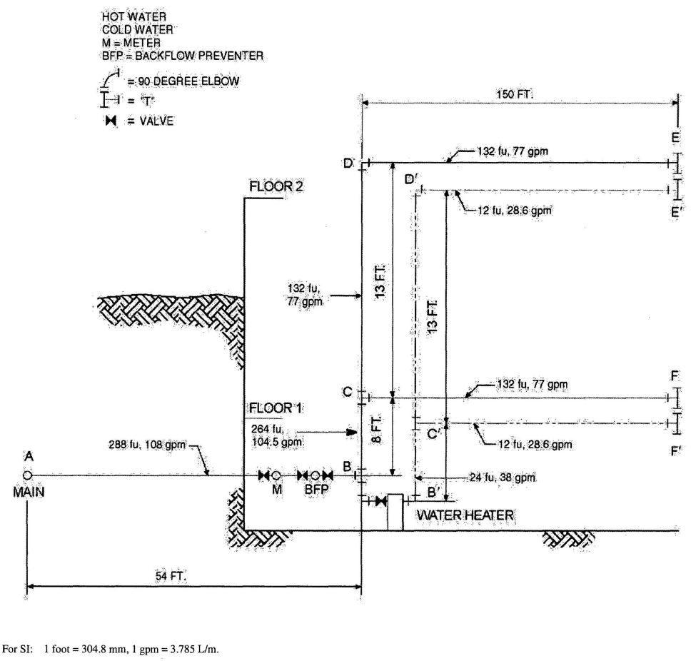
FIGURE AP103.3(1)
EXAMPLE-SIZING
| COLUMN | 1 | 2 | 3 | 4 | 5 | 6 | 7 | 8 | 9 | 10 | |
|---|---|---|---|---|---|---|---|---|---|---|---|
| Line | Description | Lb per square Inch (psi) | Gal. per min through section | Length of section (feet) | Trial pipe size (inches) | Equivalent length of fittings and valves (feet) | Total equivalent length col. 4 and col. 6 (100 feet) | Friction loss per 100 feet of trial size pipe (psi) | Friction loss in equivalent length col 8*col.7 (psi) | Excess pressure over friction losses (psi) | |
| For SI: 1 inch = 25.4 mm, 1 foot = 304.8 mm, 1 psi = 6.895 kPa, 1 gpm = 3.785 L/m. | |||||||||||
| a. To be considered as pressure gain for fixtures below main (to consider separately, omit from “I” and add to “J”). | |||||||||||
| b. To consider separately, in K use C-F only if greater loss than above. | |||||||||||
| A | Service and cold water distribution pipinga | Minimum pressure available at main | 55.00 | ||||||||
| B | Highest pressure required at a fixture (Table P2903.1) | 15.00 | |||||||||
| C | Meter loss 2″ meter | 11.00 | |||||||||
| D | Tap in main loss 2″ tap [Table AP103.3(4)] | 1.61 | |||||||||
| E | Static head loss 21 ft x 0.43 psi/ft | 9.03 | |||||||||
| F | Special fixture loss backflow preventer | 9.00 | |||||||||
| G | Special fixture loss—Filter | 0.00 | |||||||||
| H | Special fixture loss—Other | 0.00 | |||||||||
| I | Total overall losses and requirements (Sum of Lines B through H) | 45.64 | |||||||||
| J | Pressure available to overcome pipe friction (Line A minus Line I) | 9.36 | |||||||||
| FU | |||||||||||
| DESIGNATION Pipe section (from diagram) Cold water Distribution piping | AB 288 | 108.0 | 54 | 2½ | 15.00 | 0.69 | 3.2 | 2.21 | — | ||
| BC 264 | 104.5 | 8 | 2½ | 0.5 | 0.85 | 3.1 | 0.26 | — | |||
| CD 132 | 77.0 | 13 | 2½ | 7.00 | 0.20 | 1.9 | 3.08 | — | |||
| CFb 132 | 77.0 | 150 | 2½ | 12.00 | 1.62 | 1.9 | 3.08 | — | |||
| DEb 132 | 77.0 | 150 | 2½ | 12.00 | 1.62 | 1.9 | 3.08 | — | |||
| K | Total pipe friction losses (cold) | — | — | — | — | — | — | 5.93 | — | ||
| L | Difference (Line J minus Line K) | — | — | — | — | — | — | — | 3.43 | ||
| Pipe section (from diagram) Diagram Hot water Distribution Piping | A′;B′; 288 | 108.0 | 54 | 2½ | 12.00 | 0.69 | 3.3 | 2.21 | — | ||
| B′;C′; 24 | 38.0 | 8 | 2 | 7.5 | 0.16 | 1.4 | 0.22 | — | |||
| C′;D′; 12 | 28.6 | 13 | 1½ | 4.0 | 0.17 | 3.2 | 0.54 | — | |||
| C′;F′;b12 | 28.6 | 150 | 1½ | 7.00 | 1.57 | 3.2 | 5.02 | — | |||
| D′;E′;b 12 | 28.6 | 150 | 1½ | 7.00 | 1.57 | 3.2 | 5.02 | — | |||
| K | Total pipe friction losses (hot) | — | — | — | — | — | — | 7.99 | — | ||
| L | Difference (Line J minus Line K) | — | — | — | — | — | — | — | 1.37 | ||
| FIXTURE | OCCUPANCY | TYPE OF SUPPLY CONTROL | LOAD VALUES, IN WATER SUPPLY FIXTURE UNITS (wsfu) | ||
|---|---|---|---|---|---|
| Cold | Hot | Total | |||
| For SI: 1 inch=25.4 mm, 1 pound=0.454 kg. | |||||
| a. For fixtures not listed, loads should be assumed by comparing the fixture to one listed using water in similar quantities and at similar rates. The assigned loads for fixtures with both hot and cold water supplies are given for separate hot and cold water loads and for total load. The separate hot and cold water loads being three-fourths of the total load for the fixture in each case. | |||||
| Bathroom group | Private | Flush tank | 2.7 | 1.5 | 3.6 |
| Bathroom group | Private | Flush valve | 6.0 | 3.0 | 8.0 |
| Bathtub | Private | Faucet | 1.0 | 1.0 | 1.4 |
| Bathtub | Public | Faucet | 3.0 | 3.0 | 4.0 |
| Bidet | Private | Faucet | 1.5 | 1.5 | 2.0 |
| Combination fixture | Private | Faucet | 2.25 | 2.25 | 3.0 |
| Dishwashing machine | Private | Automatic | — | 1.4 | 1.4 |
| Drinking fountain | Offices, etc. | 3⁄8″ valve | 0.25 | — | 0.25 |
| Kitchen sink | Private | Faucet | 1.0 | 1.0 | 1.4 |
| Kitchen sink | Hotel, restaurant | Faucet | 3.0 | 3.0 | 4.0 |
| Laundry trays (1 to 3) | Private | Faucet | 1.0 | 1.0 | 1.4 |
| Lavatory | Private | Faucet | 0.5 | 0.5 | 0.7 |
| Lavatory | Public | Faucet | 1.5 | 1.5 | 2.0 |
| Service sink | Offices, etc. | Faucet | 2.25 | 2.25 | 3.0 |
| Shower head | Public | Mixing valve | 3.0 | 3.0 | 4.0 |
| Shower head | Private | Mixing valve | 1.0 | 1.0 | 1.4 |
| Urinal | Public | 1″ flush valve | 10.0 | — | 10.0 |
| Urinal | Public | ¾″ flush valve | 5.0 | — | 5.0 |
| Urinal | Public | Flush tank | 3.0 | — | 3.0 |
| Washing machine (8 lb) | Private | Automatic | 1.0 | 1.0 | 1.4 |
| Washing machine (8 lb) | Public | Automatic | 2.25 | 2.25 | 3.0 |
| Washing machine (15 lb) | Public | Automatic | 3.0 | 3.0 | 4.0 |
| Water closet | Private | Flush valve | 6.0 | — | 6.0 |
| Water closet | Private | Flush tank | 2.2 | — | 2.2 |
| Water closet | Public | Flush valve | 10.0 | — | 10.0 |
| Water closet | Public | Flush tank | 5.0 | — | 5.0 |
| Water closet | Public or private | Flushometer tank | 2.0 | — | 2.0 |
| GALLONS PER MINUTE | SIZE OF TAP OR TEE (inches) | ||||||
|---|---|---|---|---|---|---|---|
| 5⁄8 | ¾ | 1 | 1¼ | 1½ | 2 | 3 | |
| For SI: 1 inch=25.4 mm, 1 pound per square inch=6.895 kPa, 1 gallon per minute=3.785 L/m. | |||||||
| 10 | 1.35 | 0.64 | 0.18 | 0.08 | — | — | — |
| 20 | 5.38 | 2.54 | 0.77 | 0.31 | 0.14 | — | — |
| 30 | 12.10 | 5.72 | 1.62 | 0.69 | 0.33 | 0.10 | — |
| 40 | — | 10.20 | 3.07 | 1.23 | 0.58 | 0.18 | — |
| 50 | — | 15.90 | 4.49 | 1.92 | 0.91 | 0.28 | — |
| 60 | — | — | 6.46 | 2.76 | 1.31 | 0.40 | — |
| 70 | — | — | 8.79 | 3.76 | 1.78 | 0.55 | 0.10 |
| 80 | — | — | 11.50 | 4.90 | 2.32 | 0.72 | 0.13 |
| 90 | — | — | 14.50 | 6.21 | 2.94 | 0.91 | 0.16 |
| 100 | — | — | 17.94 | 7.67 | 3.63 | 1.12 | 0.21 |
| 120 | — | — | 25.80 | 11.00 | 5.23 | 1.61 | 0.30 |
| 140 | — | — | 35.20 | 15.00 | 7.12 | 2.20 | 0.41 |
| 150 | — | — | — | 17.20 | 8.16 | 2.52 | 0.47 |
| 160 | — | — | — | 19.60 | 9.30 | 2.92 | 0.54 |
| 180 | — | — | — | 24.80 | 11.80 | 3.62 | 0.68 |
| 200 | — | — | — | 30.70 | 14.50 | 4.48 | 0.84 |
| 225 | — | — | — | 38.80 | 18.40 | 5.60 | 1.06 |
| 250 | — | — | — | 47.90 | 22.70 | 7.00 | 1.31 |
| 275 | — | — | — | — | 27.40 | 7.70 | 1.59 |
| 300 | — | — | — | — | 32.60 | 10.10 | 1.88 |
| FITTING OR VALVE | PIPE SIZE (inches) | |||||||
|---|---|---|---|---|---|---|---|---|
| ½ | ¾ | 1 | 1¼ | 1½ | 2 | 2½ | 3 | |
| For SI: 1 inch=25.4 mm, 1 foot=304.8 mm, 1 degree=0.0175 rad. | ||||||||
| 45-degree elbow | 1.2 | 1.5 | 1.8 | 2.4 | 3.0 | 4.0 | 5.0 | 6.0 |
| 90-degree elbow | 2.0 | 2.5 | 3.0 | 4.0 | 5.0 | 7.0 | 8.0 | 10.0 |
| Tee, run | 0.6 | 0.8 | 0.9 | 1.2 | 1.5 | 2.0 | 2.5 | 3.0 |
| Tee, branch | 3.0 | 4.0 | 5.0 | 6.0 | 7.0 | 10.0 | 12.0 | 15.0 |
| Gate valve | 0.4 | 0.5 | 0.6 | 0.8 | 1.0 | 1.3 | 1.6 | 2.0 |
| Balancing valve | 0.8 | 1.1 | 1.5 | 1.9 | 2.2 | 3.0 | 3.7 | 4.5 |
| Plug-type cock | 0.8 | 1.1 | 1.5 | 1.9 | 2.2 | 3.0 | 3.7 | 4.5 |
| Check valve, swing | 5.6 | 8.4 | 11.2 | 14.0 | 16.8 | 22.4 | 28.0 | 33.6 |
| Globe valve | 15.0 | 20.0 | 25.0 | 35.0 | 45.0 | 55.0 | 65.0 | 80.0 |
| Angle valve | 8.0 | 12.0 | 15.0 | 18.0 | 22.0 | 28.0 | 34.0 | 40.0 |
| NOMINAL OR STANDARD SIZE (inches) | FITTINGS | Coupling | VALVES | ||||||
|---|---|---|---|---|---|---|---|---|---|
| Standard EII | 90-Degree Tee | Ball | Gate | Butterfly | Check | ||||
| 90 Degree | 45 Degree | Side Branch | Straight Run | ||||||
| For SI: 1 inch=25.4 mm, 1 foot=304.8 mm, 1 degree=0.01745 rad. | |||||||||
| a. Allowances are for streamlined soldered fittings and recessed threaded fittings. For threaded fittings, double the allowances shown in the table. The equivalent lengths presented above are based on a C factor of 150 in the Hazen-Williams friction loss formula. The lengths shown are rounded to the nearest half-foot. | |||||||||
| 3⁄8 | 0.5 | — | 1.5 | — | — | — | — | — | 1.5 |
| ½ | 1 | 0.5 | 2 | — | — | — | — | — | 2 |
| 5⁄8 | 1.5 | 0.5 | 2 | — | — | — | — | — | 2.5 |
| ¾ | 2 | 0.5 | 3 | — | — | — | — | — | 3 |
| 1 | 2.5 | 1 | 4.5 | — | — | 0.5 | — | — | 4.5 |
| 1¼ | 3 | 1 | 5.5 | 0.5 | 0.5 | 0.5 | — | — | 5.5 |
| 1½ | 4 | 1.5 | 7 | 0.5 | 0.5 | 0.5 | — | — | 6.5 |
| 2 | 5.5 | 2 | 9 | 0.5 | 0.5 | 0.5 | 0.5 | 7.5 | 9 |
| 2½ | 7 | 2.5 | 12 | 0.5 | 0.5 | — | 1 | 10 | 11.5 |
| 3 | 9 | 3.5 | 15 | 1 | 1 | — | 1.5 | 15.5 | 14.5 |
| 3½ | 9 | 3.5 | 14 | 1 | 1 | — | 2 | — | 12.5 |
| 4 | 12.5 | 5 | 21 | 1 | 1 | — | 2 | 16 | 18.5 |
| 5 | 16 | 6 | 27 | 1.5 | 1.5 | — | 3 | 11.5 | 23.5 |
| 6 | 19 | 7 | 34 | 2 | 2 | — | 3.5 | 13.5 | 26.5 |
| 8 | 29 | 11 | 50 | 3 | 3 | — | 5 | 12.5 | 39 |
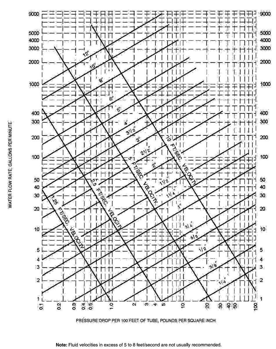
FIGURE AP103.3(2)
FRICTION LOSS IN SMOOTH PIPEa(TYPE K, ASTM B 88 COPPER TUBING)
For SI: 1 inch=25.4 mm, 1 foot=304.8 mm, 1 gpm=3.785 L/m, 1psi=6.895 kPa, 1 foot per second=0.305 m/s.
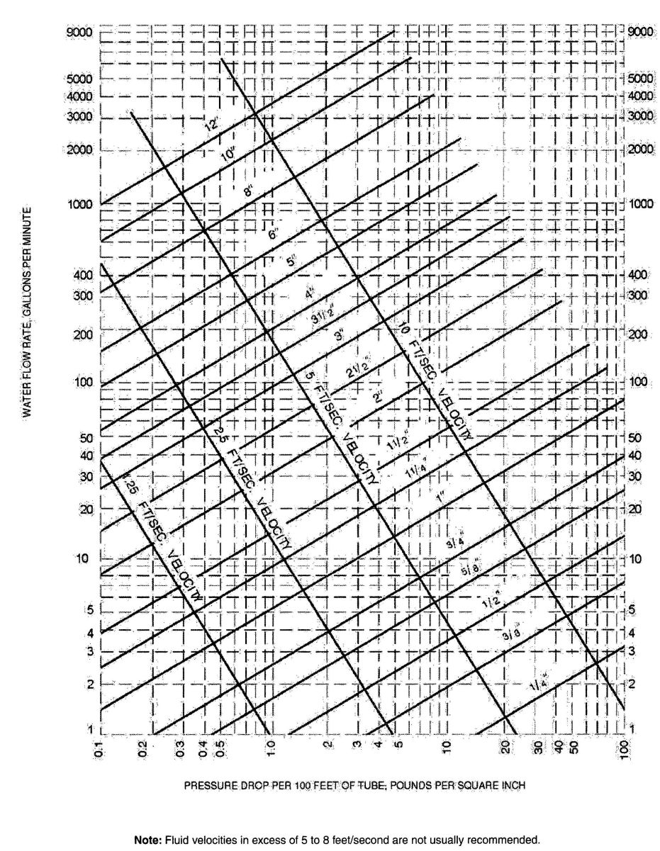
FIGURE AP103.3(3)
FRICTION LOSS IN SMOOTH PIPEa (TYPE L, ASTM B 88 COPPER TUBING)
For SI: 1 inch=25.4 mm, 1 foot=304.8 mm, 1 gpm=3.785 L⁄m, 1 psi=6.895 kPa, 1 foot per second=0.305 m⁄s.
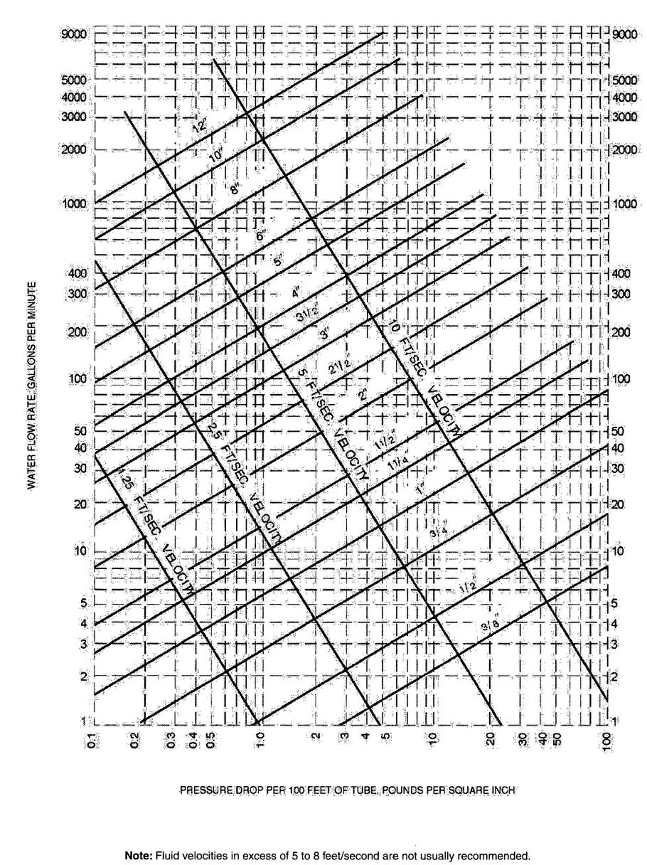
FIGURE AP103.3(4)
FRICTION LOSS IN SMOOTH PIPEa (TYPE M, ASTM B 88 COPPER TUBING)
For SI: 1 inch = 25.4 mm, 1 foot = 304.8 mm, 1 gpm = 3.785 L⁄m, 1 psi = 6.895 kPa, 1 foot per second = 0.305 m⁄s.
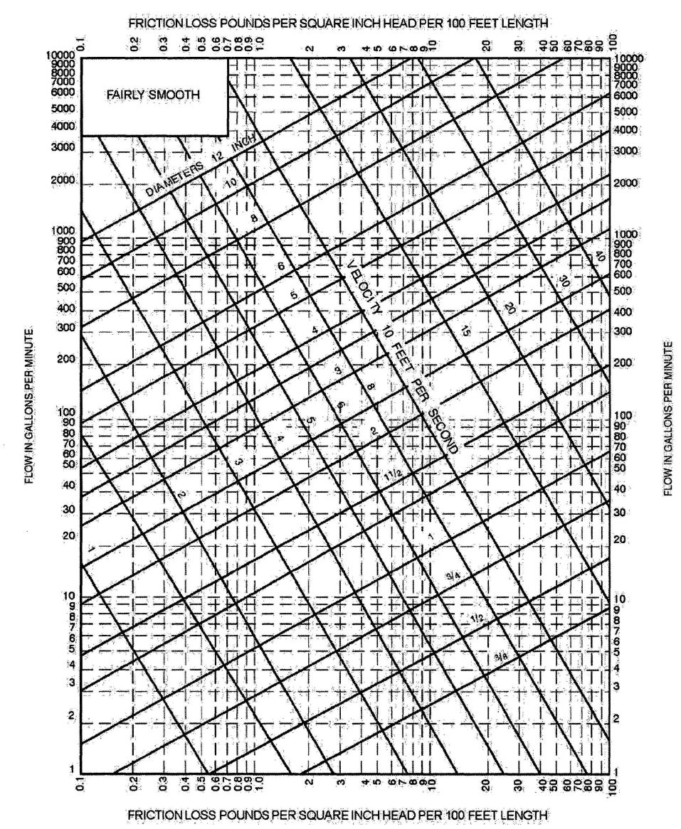
FIGURE AP103.3(5)
FRICTION LOSS IN FAIRLY SMOOTH PIPEa
For SI: 1 inch = 25.4 mm, 1 foot = 304.8 mm, 1 gpm = 3.785 L⁄m, 1 psi = 6.895 kPa, 1 foot per second = 0.305 m⁄s.
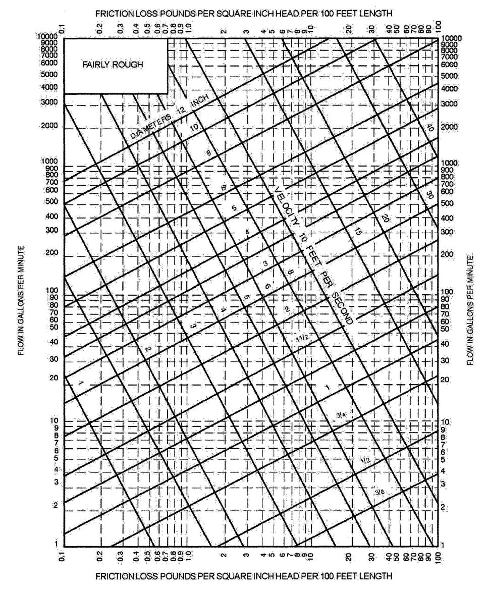
FIGURE AP103.3(6)
FRICTION LOSS IN FAIRLY ROUGH PIPEa
For SI: 1 inch = 25.4 mm, 1 foot = 304.8 mm, 1 gpm = 3.785 L⁄m, 1 psi = 6.895 kPa, 1 foot per second = 0.305 m⁄s.
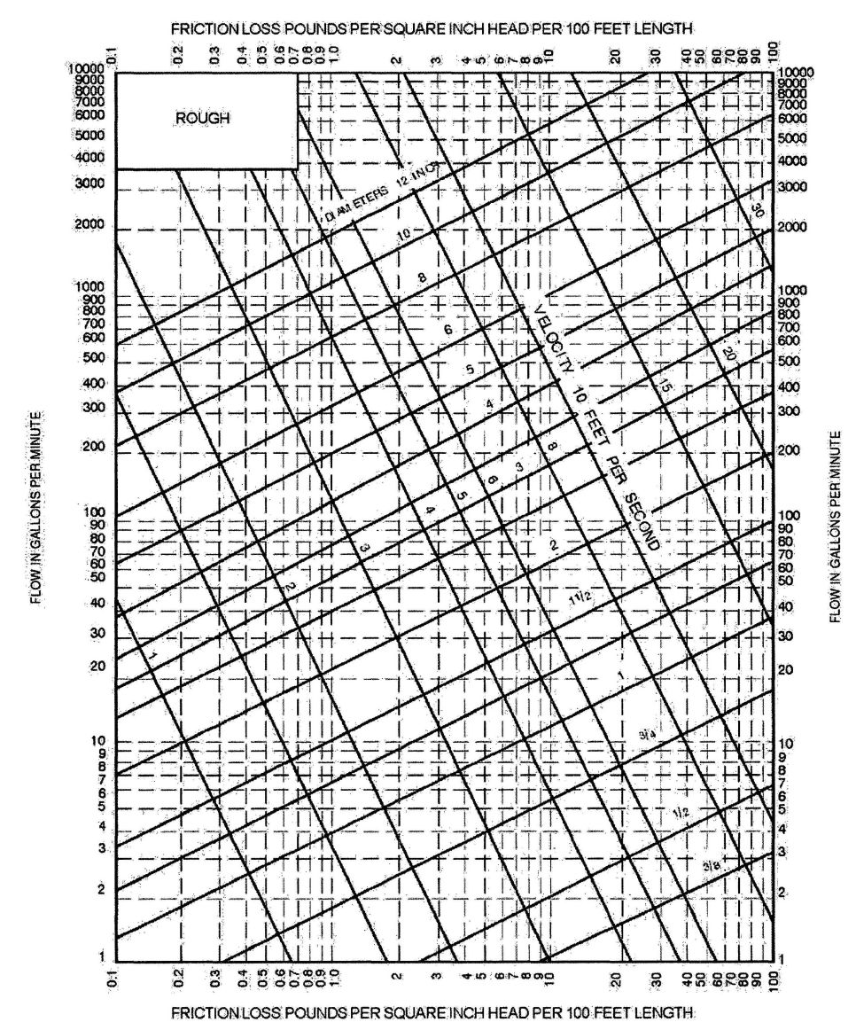
FIGURE AP103.3(7)
FRICTION LOSS IN FAIRLY ROUGH PIPEa
For SI: 1 inch = 25.4 mm, 1 foot = 304.8 mm, 1 gpm = 3.785 L⁄m, 1 psi = 6.895 kPa, 1 foot per second = 0.305 m⁄s.
AP201.1 Size of water-service mains, branch mains and risers. The minimum size water service pipe shall be 3⁄4 inch (19.1 mm). The size of water service mains, branch mains and risers shall be determined according to water supply demand [gpm(L⁄m)], available water pressure [psi (kPa)] and friction loss caused by the water meter and developed length of pipe [feet (m)], including equivalent length of fittings. The size of each water distribution system shall be determined according to the procedure outlined in this section or by other design methods conforming to acceptable engineering practice and approved by the code official:
CALIFORNIA RESIDENTIAL CODE — MATRIX ADOPTION TABLE
APPENDIX Q – ICC INTERNATIONAL RESIDENTIAL CODE ELECTRICAL PROVISIONS#8260; NATIONAL ELECTRICAL CODE CROSS-REFERENCE
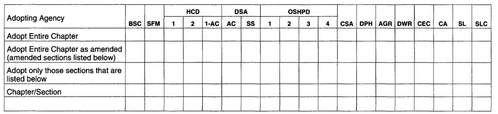
The provisions contained in this appendix are not mandatory unless specifically referenced in the adopting ordinance.
(This appendix is informative and is not part of the code. This table is a cross-reference of the International Residential Code, Chapters 34 through 43, and the 2008 National Electrical Code, NFPA 70).
693 694| Adopting Agency | BSC | SFM | HCD | DSA | OSHPD | CSA | DPH | AGR | DWR | CEC | CA | SL | SLC | ||||||
|---|---|---|---|---|---|---|---|---|---|---|---|---|---|---|---|---|---|---|---|
| 1 | 2 | 1-AC | AC | SS | 1 | 2 | 3 | 4 | |||||||||||
| Adopt Entire Chapter | X | ||||||||||||||||||
| Adopt Entire Chapter as amended (amended section listed below) | |||||||||||||||||||
| Adopt only those sections that are listed below | |||||||||||||||||||
| Chapter/Section | |||||||||||||||||||
Note: The effective date of these standard shall be March 1, 2012 or ninety (90) days after the corresponding maps are completed and readily available to the general public, whichever is the later date.
Table R301.2(1) Revise as follows:
Replace the Flood Hazards cell in table as follows:
| FLOOD HAZARDS | |
|---|---|
| j. Jurisdictions with Areas Protected by the Facilities of the Central Valley where Flood Levels are Anticipated to Exceed Three Feet for the 200-Year Flood Event, as defined in Section AR102, shall fill in this part of the table with “Yes” or “No”. | |
| NFIPg | CVFPPj |
AR101 General. The provisions of this section shall apply to new construction, changes of use or repair and to substantial improvement and restoration of substantial damage of buildings in areas protected by the facilities of the Central Valley Flood Protection Plan, as established in Table R301.2(1), where flood levels are anticipated to exceed three feet for the 200-year flood event. Except as specifically required by this section, buildings and structures shall meet applicable provisions of this code.
AR101.1 Construction documents. Construction documents shall include the WSEL200 and the elevation(s) of the floor(s), and, as applicable, the elevation(s) and slopes of roofs, of the building or structure.
AR102 Definitions.
The following words and terms shall, for the purpose of this section, have the meanings shown.
AREAS PROTECTED BY THE FACILITIES OF THE CENTRAL VALLEY FLOOD PROTECTION PLAN WHERE FLOOD LEVELS ARE ANTICIPATED TO EXCEED THREE FEET FOR THE 200-YEAR FLOOD EVENT. Geographical areas identified by the state as “Areas Protected by the Facilities of the Central Valley Flood Protection Plan where Flood Levels are Anticipated to Exceed Three Feet for the 200-Year Flood Event” in accordance with the Health and Safety Code Section 50465. Published data from the California Department of Water Resources can be obtained online at the following website: www.water.ca.gov/BuildingCodes.
Note: The facilities of the Central Valley Flood Protection Plan are identified in the following counties: Butte, Colusa, Fresno, Glenn, Lake, Madera, Merced, Plumas, Sacramento, San Joaquin, Solano, Stanislaus, Sutter, Tehama, Yolo and Yuba. Determination of additional facilities is ongoing.
CENTRAL VALLEY. Any lands in the bed or along or near the banks of the Sacramento River and the San Joaquin River and any of their tributaries or connected therewith, or upon any land adjacent thereto, or within any of the overflow basins thereof, or upon any land susceptible to overflow therefrom. The following countries and the incorporated municipalities within these counties, in whole or in part, are in the Central Valley: Alpine, Amador, Butte, Calaveras, Colusa, El Dorado, Fresno, Glenn, Lake, Lassen, Madera, Mariposa, Merced, Modoc, Napa, Nevada, Placer, Plumas, Sacramento, San Benito, San Joaquin, Shasta, Sierra, Siskiyou, Solano, Stanislaus, Sutter, Tehama, Tuolumne, Yolo and Yuba. A map that delineates the Central Valley can be obtained online at the following website: www.water.ca.gov/BuildingCodes.
EVACUATION LOCATION. A location no less than one (1) foot (0.30 meter) above the WSEL200 where occupants are expected to congregate pending evacuation and from which occupants may be evacuated during conditions of flooding, such as a space within the building that has an exit door or operable window; a deck, balcony, porch, rooftop platform or rooftop area; or combinations thereof.
FACILITIES OF THE CENTRAL VALLEY FLOOD PROTECTION PLAN. The facilities referenced herein include the facilities of State Plan of Flood Control and other flood management facilities in the Central Valley evaluated under the Central Valley Flood Protection Plan, which will be completed in 2012 and updated every 5 years thereafter. The facilities of State Plan of Flood Control include the state and federal flood control works (levees, weirs, channels, and other features) of the Sacramento River Flood Control Project described in Water Code Section 8350, and flood control projects in the Sacramento River Flood Control Project described in Water Code Section 8350, and floor control projects in the Sacramento River and San Joaquin River watersheds authorized pursuant to Article 2 (commencing with Water Code section 12648) of Chapter 2 of Part 6 of Division 6 for which the Central Valley Flood Protection Board or the Department of Water Resources has provided the assurances of nonfederal cooperation to the United States, and those facilities identified in Water Code Section 8361.
ROUTE TO THE EVACUATION LOCATION. The path through and along which occupants move from the habitable areas of building or structure that are below the WSEL200 to the evacuation location.
SUBSTANTIAL DAMAGE. Damage of any origin sustained by a structure whereby the cost of restoring the structure to its before damaged condition would equal or exceed 50 percent of the market value of the structure before the damage occurred.
SUBSTANTIAL IMPROVEMENT. Any repair, reconstruction, rehabilitation, addition or improvement of a building or structure, the cost of which equals or exceeds 50 percent of the market value of the structure before the improvement or repair is started. If the structure has sustained damage, any repairs are considered substantial improvement regardless of
697the actual repair work performed. The term does not, however, include either:
WSEL200. The water surface elevation (WSEL) of the 200-year flood event that is identified by the state when it identified areas that receive protection from the facilities of the Central Valley Flood Protection Plan.
AR103 Structural stability. Portions of buildings and structures that support evacuation locations shall be designed, constructed, connected and anchored to resist flotation, collapse or permanent lateral movement resulting from the hydrostatic loads anticipated during conditions of flooding anticipated for the 200-year flood event.
Exception: When one flood vent (minimum) is provided on two opposite sides of the building or structure that comply with Figure AR103.
AR103.1 Determination of loads. Hydrostatic loads, based on the depth of water determined by the WSEL200 shall be determined in accordance with Chapter 5 of ASCE 7. Reduction of hydrostatic loads may be accomplished by allowing for the automatic entry and exit of floodwaters to minimize unbalanced loads. Such means shall be designed by a registered design professional and include, but are not limited to, openings, valves, and panels designed to yield under load.
AR104 Evacuation Locations. An evacuation location and a route to the evacuation location shall be provided.
AR104.1 Route to evacuation location. A route shall be allowed through any number of intervening rooms or spaces. Doors along the route shall be openable without the use of a key, lock, special knowledge or effort.
AR104.2 minimum size requirements. Evacuation locations shall provide a minimum gross floor area of 7 square feet (0.65 m2) per occupant, based on the occupant load of the portions of the building that are below WSEL200. The area provided shall be adequate to accommodate the occupant load of the upper levels as well as the anticipated occupant load from the area below the WSEL200.
AR105 Space within the building. If the evacuation location is a space within a building, the evacuation location shall be provided with a means for occupants to be evacuated out of the building specified in Section AR105.1, R105.2 or R105.3. The means for occupants to be evacuated out of the building shall address the mobility of the occupants.
AR105.1 Windows, minimum size and dimensions. A minimum of one window shall be provided that meet the minimum size, minimum dimensions and operational constraints of Section R310. The number of such windows shall be appropriate for the occupancy or occupancies of the portions of the building that are below WSEL200.
Note: It is the intent of this section that windows be of sufficient number, sizes and dimensions to reasonably accommodate the needs and limitations of the occupants of the building. Reasonable judgment in the application of this requirement must be exercised by the building official.
AR105.2 Exterior doors to decks, balconies and porches. Exterior doors to decks, balconies and porches shall be sized in accordance with Section R311.
AR105.3 Means of escape to rooftops from spaces within a building. The means of escape to rooftops shall be permitted to be provided by a stairway, ramp, alternating tread device, fixed ladder or other means approved by the building official.
AR106 Decks and balconies that are evacuation locations. Decks and balconies that have finish floors no less than one (1) foot (0.30 meter) above the WSEL200 shall be permitted to be evacuation locations. When a deck or balcony used as an evacuation location is not at the same level as a floor within the building, it shall be permitted to be accessed by a stairway, ramp, alternating tread device, fixed ladder or other means approved by the building official.
AR106.1 Live load. Decks and balconies that are evacuation locations shall be designed for the live load required in Table R301.5.
AR106.2 Evacuation route. Evacuation routes to decks and balconies that are evacuation locations shall be permitted to be provided by a stairway, ramp, alternating tread device, fixed ladder or other means approved by the building official.
AR107 Rooftop evacuation locations. Rooftop evacuation locations shall be permitted to include rooftop platforms and rooftop areas provided that they are no less than one (1) foot (0.30 meter) above the WSEL200. A minimum horizontal distance of 3 feet (0.91 meter) shall be provided between the lower edge of the rooftop evacuation location, access point and the evacuation location lower perimeter.
AR107.1 Rooftop platforms required. A rooftop platform shall be provided if the roof covering material are:
AR107.2 Roof live loads. Roof areas that are rooftop evacuation locations and roofs that support rooftop platforms that are evacuation locations shall be designed for the roof live load required for the occupancy as required in CBC Table 1607.2.
698AR107.3 Evacuation routes to rooftop evacuation locations. Evacuation routes to rooftop evacuation locations shall be permitted to be provided by a stairway, ramp, alternating tread device, fixed ladder or other means approved by the building official.
AR107.4 Perimeter protection. The perimeter of rooftop evacuation locations shall be protected by:
AR107.5 Utility/equipment buffer zone. A separation of 48 inches shall be provided between an evacuation location and any mechanical equipment, photovoltaic system, utility service drop or other utility line. Electrical service lines shall not pass over evacuation locations.
AR108 Attics that are evacuation locations. Attics that have finish floors no less than one (1) foot above the WSEL200 shall be permitted to be evacuation locations.
AR108.1 Headroom. When an attic is used as an evacuation location, the minimum headroom of the required area shall be 30 inches (762 mm) with 50 percent of the required area having a headroom of 60 inches (1524 mm).
AR108.2 Attic flooring. The required area of the evacuation location shall be solidly sheathed.
AR108.3 Attic live loads. Attic areas that are used as evacuation locations shall be designed for the attic with limited live load requirement in Table R301.5.
AR108.4 Evacuation routes to attic evacuation locations. In Group R-3.1 Occupancies that are subject to the requirements of Chapter 11A or 11B, such requirement shall apply to the evacuation routes to attics. In Group R-3 Occupancies, evacuation routes to attic evacuation locations shall be permitted to be provided by a stairway, ramp, alternating tread device fixed ladder or other means approved by the building official.
AR108.5 Means of escape from attics. The means of escape from attics shall comply with Section AR105.
AR109 Alternate means of protection.
AR109.1 Request for approval of alternate means of protection. Request for approval to use an alternative means of protection shall be made in writing to the building official by the owner or the owner's authorized representative. The request shall be accompanied by a full statement of the conditions and sufficient evidence that the proposed alternate means of protection provides reasonable protection to occupants. The building official shall require the owner to obtain a written statement from the applicable emergency management authority regarding plans and processes related to notification of anticipated conditions of flooding, warnings, evacuations and other pertinent conditions relative to the proximity of nearby levees. The building official shall also require the owner to obtain a written statement and findings from the entity that has jurisdiction over the management, maintenance, monitoring and control of flood protection works in the vicinity of the location of the owner's property, such statement shall comment on the viability of the proposed alternate means of protection. The building official may request written statements from the Central Valley Flood Protection Board, the California Department of Water Resources and the California Emergency Management Agency.
Approval of a request for use of an alternative means of protection made pursuant to these provisions shall be limited to the particular case covered by the request and shall not be constructed as establishing any precedent for any future request except in substantially equivalent situtations.
Note: Contact information for the California Department of Water Resources and the Department's Directory of Flood Officials, which includes levee and reclamation district boundary maps, is available on-line at the following website: www.water.ca.gov/BuildingCodes. The department of Water Resources Building Code Project Engineer can be contacted at 916-574-1451. The Central Valley Flood Control Board Chief Engineer can be contacted at 916-574-0609. The California Emergency Management Agency Inland Region Program Manager can be contacted at 916-845-8488.
AR109.2 Appeals. When a request for an alternate means of protection has been denied by the building official, the applicant may file a written appeal with the board of appeals. In considering such appeal, the board of appeals may provide additional information to, and request additional written statements from the Central Valley Flood Protection Board, the California Department of Water Resources and the California Emergency Management Agency. If such additional written statements are provided, the board of appeals shall consider those statements.
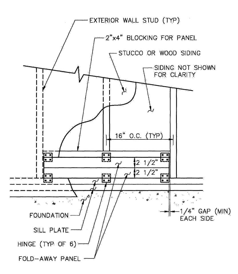
FIGURE K103.1
N.T.S.
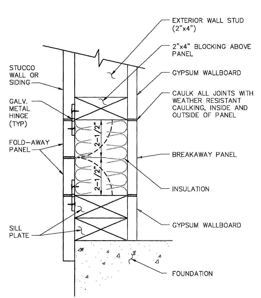
FIGURE K103.1
N.T.S.
California Residential Code
(Title 24, Part 2.5, California Code of Regulations)
ACCESS
To attic R807
To crawl space R408.4
ACCESSORY STRUCTURE
Definition R202
ADDRESS (Site) R319
ADMINISTRATION, CALIFORNIA Chapter 1, Division 1
General 1.1
Dept. of Housing and Community Development 1.2
Office of the State Fire Marshal 1.11
ADMINISTRATION DIVISION II Chapter 1
Authority R104
Entry R104.6
Inspections R109
Permits R105
Purpose R101.3
Violations R113
ALLOWABLE SPANS
Of floor joists R502.3, R505.3.2
Of headers R602.7, R603.6, R613.10
Of rafters and ceiling joists R802.4, R802.5, R804.3.1, R804.3.2
ALTERNATE MATERIALS (see MATERIALS) R104.11
ANCHOR BOLTS R403.1.6
APPEAL
Board of 1.2.7, R112.1
Right of 1.2.7, R112
APPLIANCE
Flue area R1003.14
APPLICATION
Plywood R703.3
APPROVED
Definition R 202
AREA
Flue (appliances) R1003.14
Flue masonry R1003.15
ASPHALT SHINGLES 5905.2
ATTIC
Access R807
AUTOMATIC FIRE SPRINKLER SYSTEMSR313
BALCONY, EXTERIOR
Definition R202
BASEMENT WALL
Definition R202
BATH AND SHOWER SPACES R307
BEAM SUPPORTS R606.14
BEARING
Of joists R502.6
BORED HOLES (see NOTCHING)
BUILDING
Definition R202
Existing, definition R202
BUILDING OFFICIAL
Definition R202
BUILDING PLANNING
Automatic fire sprinkler systems R313
Carbon monoxide alarms R315
Ceiling height R305
Decay protection R317
Design criteria R301
Emergency escape R310
Exterior wall R302.1
Finishes R315
Fire-resistant construction R302
Foam plastic R316
Garages and carports R309
Glazing R308
Guardrails R312
Handrails R311.7.7, R311.8.3
Insulation R302.10
Landing R311.4.3, R311.5.4, R311.6.2
Light, ventilation and heating R303
Means of egress R311
Minimum room area R304
Planning Chapter 3
Plumbing fixture clearances R307
Radon protection Appendix F
Ramps R311.8
Sanitation R306
Site address R319
Smoke alarms R314
Stairways R311.7
Storm shelters R323
Termite protection R318
BUILT-UP GIRDERS (see GIRDERS)
BUILT-UP ROOFING (see ROOFING)
CARBON MONOXIDE ALARMS R315
CARPORT R309.4
CEILING
Finishes R805
Height R305
CHASESR606.7
705CHIMNEYS
And fireplaces Chapter 10
Clearance R1003.18
Corbeling R1003.5
Crickets R1003.20
Design (masonry) R1003.1
Factory-built R1005
Fireblocking R1003.19
Flue area R1003.14, R1003.15
Flue lining R100311
Load R1003.8
Multiple flue R1003.14
Spark arrestors R1003.9.1
Termination R1003.9
Wall thickness R1003.10
CLAY
Tiles R905.3
CLEANOUT
Masonry chimney R1003.17
CLEARANCE
For chimneys R1003.18
COLUMNS R407
COMBUSTIBLE
Materials R202
CONCRETE
Compressive Strength R402.2
Floors (on ground) R506
Tile (roof) R905.3
Weathering Figure R301.2(3), R402.2
CONSTRUCTION
Cavity wall masonry R608
Flood-resistant R322
Floors Chapter 5
Footings R403
Foundation material R402
Foundation walls R404
Foundations Chapter 4
Grouted masonry R609
Masonry R606, R607, R608, R609, R610
Reinforced hollow unit masonry R609.4
Roofs Chapter 8
Steel framing R505, R603, R804
Wood framing R502, R602, R802
Walls Chapter 6
COURT
Definition R202
COVERING
Exterior R703
Interior R702
Roof Chapter 9
Wall Chapter 7
CRAWL SPACE R408
CRITERIA
Design R301
DECAY
Protection against R317
DECK
Supported by exterior wall R502.2.2
Wood/plastic composite boards R502.1.7, R502.2.2.4
DEFINITIONS
Building R202
DESIGN
Criteria R301
DOORS
Exit R311.4.1
Exterior R612
DRAFTSTOPPING R302.12, R502.12
DRAINAGE
Foundation R405
DRILLING AND NOTCHING (see NOTCHING)
DWELLING
Definition R202
DWELLING UNIT
Definition R202
Separation R302.2, R302.3
EMERGENCY ESCAPE R202, R310
ENTRY 1.2.4, R104.6
EXTERIOR
Covering R703
Insulation finish systems R703.9
Lath R703.6.1
Plaster R703.6
EXTERIOR WALL
Definition R202
FACTORY BUILT
Chimneys R1005
Fireplace stoves R1005.3
Fireplaces R1004
FASTENING Table R602.3(1)
FENESTRATION
Definition R202
FINISHES
Flame spread and smoke density R315
For ceilings R805
Interior R315, R702
FIRE BLOCKING
Barrier between stories R302.11, R602.8
Chimney R1003.19
Fireplace R1001.12
FIRE-RESISTANT CONSTRUCTION R302
706FIRE SPRINKLER SYSTEM
Inspections of R313.3.8
Sizing of R313.3.6
Sprinkler location R313.3.1.1
FIREPLACES Chapter 10
Clearance R1001.11
Corbeling R1001.8
Factory-built R1004
Fire blocking R1001.12
Walls R1001.5
FLAME SPREAD INDEX R302.9, R302.10
FLASHING R703.7.5, R703.8, R903.2, R905
FLOORS
Concrete (on ground) R506
Steel framing R505
Treated-wood (on ground) R504
Wood framing R502
FLUE
Area R1003.14, R1003.15
Lining R1003.11, R1003.12
Multiple R1003.13
FOAM PLASTICS R316
FOOTINGS R403
FOUNDATIONS Chapter 4
Cripple walls R602.9, R602.10.9, R602.11.2
Frost protection R403.1.4.1
Inspection R109.1.1
Walls R404
FRAME
Inspection R109.1.4
GARAGES R309
GIRDERS R502.5
GLAZING R308
Aggregate R303.1
Protection of openings R301.2.1.2
GRADE
Definition R202
Of lumber R502.1, R602.1, R802.1
Plane, definition R202
GRAY WATER Appendix O
GROUND
Floors (on ground) R504, R506
GROUTED MASONRY (see MASONRY) R609
Reinforced R609.3
GUARDS R312
Definition R202
GYPSUM
Wallboard R702.3
HABITABLE SPACE
Definition R202
HALLWAYS R311.6
HANDRAILS R311.7.7, R311.8.3
Definition R202
HEADERS
SIP R613.10
Steel R603.6
Wood R602.7
HEARTH R1001.9
Extension R1001.9, R1001.10
HEATERS
Masonry R1002
HEATING R303.8
HEIGHT
Ceiling R305
HOLLOW-UNIT MASONRY
(see MASONRY) R607.2.2.2, R608.1.1.2
Reinforced R609.4
HOT TUBS Appendix G
INLET
To masonry chimneys R1003.16
INSPECTION
Card AE305.3
On site 1.2.3, R109.1
INSTALLATION
Existing Appendix J
Of flue liners R1003.12
INSULATION R302.10
INTERIOR
Lath R702.2.3
Other finishes R702.5
Plaster R702.2
Wall covering Chapter 7
JOIST
Bearing R502.6, R606.14.1
KITCHEN
Definition R202
LABELED
Definition R202
LABELING
Definition R202
LANDINGS R311.3, R311.7.1, R311.7.5, R311.8.2
LATERAL SUPPORT R502.7, R606.9, R610.5.2
LATH
Exterior R703.6.1
Interior R702.2.3
707LAVATORIES
Clearances R307
LIABILITY R104.8
LIGHT, VENTILATION AND HEATING R303
LINING
Flue R1003.11, R1003.12
LINTEL R606.10, R611.8, R703.7.3, R1001.7
LISTED and LISTING
Definition applied to building provisions R202
LOAD
Additional R1003.8
Roof R301.6
Seismic risk map Figure R301.2(2)
Snow load map Figure R301.2(5)
Wind speed map Figure R301.2(4)
LOADS
Dead load R301.4
Live load R301.5
LOADS, LIVE AND DEAD
Definition R202
LUMBER
Grade R502.1, R602.1, R802.1
MANUFACTURED HOME
Provisions Appendix E
MASONRY
Anchorage R606.11
Cavity wall R608
Chases R606.7
General R606
Grouted R609
Hollow unit R202, R607.2.2.2, R608.1.1.2
Inspection R109.1.4
Reinforced grouted R609.3
Reinforced hollow unit R609.4
Seismic requirements R606.12
Solid, definition R202
Veneer R703.7
Veneer attachment R703.4
MATERIALS
Alternate 1.2.6, R104.11
Combustible R202, R1003.18, R1003.19 R1001.11, R1001.12
For flue liners R1003.11
For hearth extension R1001.9
For siding R703.3
MEMBRANE
Penetration R302.4.2
Polyethylene R504.2.2, R506.2.3
Water proofing R406.2
Water-resistive R703.2
METAL
Roof panels R905.10
Roof shingles R905.4
METHODS
Water distribution pipe sizing Appendix P
MODIFICATIONS R104.10
MOISTURE CONTROL R601.3
MORTAR
Joints R607.2.1.1
MULTIPLE FLUES R1003.13
NONCOMBUSTIBLE MATERIAL
Definition R202
NOTCHING
Steel joists R505.2.5, R505.3.5, R804.2.5, R804.3.4
Steel studs R603.2.5, R603.3.4
Wood joists R502.8, R802.7.1
Wood studs R602.6
Wood top plates R602.6.1
OCCUPIED SPACE
Definition R202
PARAPETS R317.2.2, R606.2.4
PARTICLEBOARD
Floor R503.3
Walls R605
PERMITS 1.2.3, R105
PIERS R606.6
PLANNING
Building Chapter 3
PLANS 1.2.3, R106
PLASTER
Exterior R703.6
Interior R702.2
PLUMBING
Fixture clearances R307
Inspection R109.1.2
PLYWOOD
Application R703.3
Materials, walls R604
PRECAST CONCRETE
Footings R403.4
Foundation material R402.3.1
Foundation walls R404.5
PRIVATE
Sewage disposal system Appendix I
PROTECTION
Against decay and termites R319, R320
Against radon Appendix F
PURLINS R802.5.1
PURPOSE 1.1.2, R101.3
708RADON
Map Appendix F
RAFTERS
Grade of lumber R802.1
Spans R802.5, Tables R802.5.1(1) – R802.5.1(8)
RAMPS R311.8
RESISTANT SIDING MATERIAL (see MATERIALS)
RIDGE BOARD R802.3
ROOF
Coverings R905
Drainage R903.4
Flashing R703.8, R903.2, R905
Steel framing R804
Wood framing R802
ROOF-CEILING CONSTRUCTION (see CONSTRUCTION) Chapter 8
Wind uplift R802.11, R804.3.9
ROOFING
Built-up R905.9
Liquid-applied coating R905.15
Modified bitumen R905.11
Sprayed polyurethane foam R905.14
Thermoplastic single-ply R905.13
Thermoset single-ply R905.12
ROOM
Minimum Sizes R304
SANITATION R306
SEISMIC RISK MAP Figure R301.2(2)
SHAKES
Wood R702.6, R703.5, R905.8
SHINGLE
Asphalt shingles R905.2
Metal R905.4
Slate R905.6
Wood R905.7
SHOWER
Compartment R307.2
SIDING
Exterior coverings R703
SITE
Address R319
Preparation R408.5, R504.2, R506.2
SIZE
Of rooms R304
SKYLIGHTS R308.6
SLATE SHINGLES R905.6
SMOKE ALARMS R314
SMOKE-DEVELOPED INDEX R302.9, R302.10
SNOW LOAD MAP R301.2(5)
SPANS
Steel (allowable) R505.3.2, R804.3.2.1
Wood (allowable) R502.3, R802.5
STACK BOND R606.8
STAIRWAYS R311.7
STANDARDS Chapter 44, Appendix G
STEEL
Fireplace units R1001.5.1
Floor construction R505
Roof-ceiling construction R804
Walls R603
STORM SHELTERS R323
STORY
Definition R202
STRUCTURAL INSULATED PANEL (SIP) R613
STUDS
Spacing R602.3.1
Steel R603.2, R603.3
Wood R602.2, R602.3
SUPPLY
Water R313.3.5
SUPPORT
Of decks R502.2.2
Of floor joists R502.6, R505.3.2
Of masonry chimneys R1003.2, R1003.3, R1003.4
TEMPERATURE ISOLINES Figure R301.2(1)
TERMINATION
Of chimneys R1003.9
TERMITES
Infestation probability map Figure R301.2(6)
Protection R318
THICKNESS
Of chimney walls R1003.10
TIES
Veneer R703.7.4
TILE
Shingles (clay and concrete) R905.3
TOWNHOUSE
Definition R202
Scope R101.2
Separation R302.2
TRUSSES
Steel R505.1.3, R804.3.7
Wood R502.11, R802.10
UNDER FLOOR
Space R408
UNVENTED ATTIC ASSEMBLIES R806.4
709VAPOR RETARDERS R601.3
Definition R202
VENEER
Masonry R703.7
VENTILATION
Roof R806
Under floor R408.1
VIOLATIONS
And penalties R113
WALLBOARD
Gypsum R702.3
WALLS
Bracing, steel R603.9
Bracing, wood R602.10
Construction Chapter 6
Covering Chapter 7
Cripple R602.9
Deflection R301.7
Exterior covering R703
Finishes R315, R702
Fireplace R1001.5
Foundation R404
Insulating concrete form R611.3, R611.4, R611.5.3
Steel framing R603
Structural insulated panels (SIP) R613
Thickness, masonry chimneys R1003.10
Wood framing R602
WATER CLOSET R306.1
WATERPROOFING
And dampproofing R406
WIND SPEED MAP Figure R301.2(4)
WINDOW R612
Fall prevention devices R612.3
Opening limiting devices R612.4
WOOD
Floor construction R502
Foundation walls R404.2
Roof-ceiling construction R802
Shakes R905.8
Shingles R905.7
Trusses R502.11, R802.10
Walls R602
YARD
Definition R202